

USER INSTRUCTIONS
P O R T E R
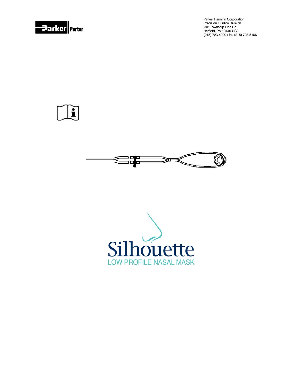
Silhouette Disposable Breathing Circuit
Silhouette -PD, -SM, -MD, -LG
Reusable Section
SIL-CONN-KIT
Smaller hose to Flowmeter
Larger hose to Vacuum Control Device
F O R
Disposable Section
Usable with
Porter Automatic Vacuum Switch (AVS-5000)
Porter Vacuum Control Block [5501-RK]
Matrx Vacuum Control Device (on flowmeter)
The Quality System for Porter Instrument is Certified to ISO 13485. The scope of our registration is: “The design,
manufacture, distribution and servicing of Dental Flowmeters, Gas Scavenging Systems, Gas Distribution
Systems and Office Communication Systems for use in the Dental Profession.
FM-1313 Rev. D 3/17

1
Silhouette Introduction
Please review brief instructional setup and
usage videos at
www.porterinstrument.com/silhouette
The Silhouette low profile nasal mask design
provides to the Medical Health Care market a mask
and breathing circuit solution that will allow high
visibility to the medical professional [especially
dentist], and provide an adhesive based seal onto
the patient’s face, allowing its built-in scavenging
system to effectively remove excess/exhaled nitrous
oxide [N2O], with minimal loss to the environment. It
allows the patient to receive the proper amount of
Oxygen and Nitrous Oxide with normal respiratory
effort.
The Nasal Mask is placed first (adhesive lamination
cover removed first) on to the patient's nose. The
Comfort Tubing is placed around the patient's ears.
The Reusable Section is attached to the Fresh Gas
and Vacuum Control Device connections. The Slide
Bolo is placed to secure the Circuit at the patient's
neck, completing a multi-point secure placement on
the patient’s face. A Fresh Gas Mixture of nitrous
oxide and oxygen is delivered from the Flowmeter
into the Circuit and into patient's nasal cavity via
the Mask; exhalation is scavenged through to the
Vacuum Control Device. Disposable Section is
disposed after use.
The sight lines from the medical professional to the
patient’s mouth (work area) created by the low
profile are superior.
The medical professional can easily manipulate the
patient’s mouth without interference to the fit of the
Circuit, while the patient can turn the head side to
side in comfort, without losing the seal.
Use Silhouette with or without a Bag Tee (see
photos of Reusable vacuum and fresh gas
attachments to Porter and Matrx flowmeters).
Matrx
Porter with AVS (and without Bag Tee)
Please review brief instructional setup, how to
retrofit, and usage videos at
www.porterinstrument.com/silhouette
The Silhouette Circuit may be used with or without a
Bag Tee. When used with a Bag Tee (including those
of most brands of flowmeters) the 3-Liter Breathing
Bag should be capped off using the Cap
(62905510W) found in kit SIL-CONN-KIT. The fresh
gas Adapter (PA-1629-000) in the kit provides a
22mm adapter to 5-7 mm taper for the Reusable
paratubing hose (B-5581-000).
Note: Primarily, the 4 holes featured in every
Silhouette Mask provides air intake. Alternatively,
patient inhalation through Silhouette Circuit (with
Total Flow delivery of approximately 5 L/min or
lower) will open the Emergency Air Intake EAI valve
on a Bag Tee for supplemental air intake.
Do not block the 4 holes during a procedure.

2
Silhouette is simple to attach to a Flowmeter
without a Bag Tee. Please review brief
instructional setup and usage videos at
www.porterinstrument.com/silhouette
For Silhouette and Vacuum and Bag Tee:
(Refer to item (#) in parts list Figure 1)
1. Existing Bag Tee assembly: Detach the 3 L
bag from the bottom of the bag tee (#16).
2. Fit the Silhouette Cap to the Bag (bottom)
port and the Adapter to the 22mm port.
3. The Circuit design has Disposable and
Reusable sections (connected to flowmeter
and vacuum source). Use Silhouette
Reusable SIL-CONN-KIT Connector Kit.
Attach smaller ID hose end to flowmeter
Adapter. Attach larger ID hose end to AVS
or other vacuum source.
4. Attach Vacuum Hoses (#15): Refer to Figure 1.
5. Automatic Vacuum Switch: Attach one end of the
Reusable vacuum hose (#15) to the Union of the
Silhouette Disposable Circuit (diameter indexed)
and the other end to the MASK port (labeled on
body) of the AVS (#1). Attach a second vacuum
hose (#15) to the VAC port (labeled on body) of
the AVS (#1), then insert straight end of adapter
(#20) into the other end of the vacuum hose and
the tapered end of the adapter into the High
Volume Evacuation (HVE) Line.
6. Vacuum Control Block: Attach one end of the
Reusable vacuum hose (#9) to the Union of the
Silhouette Disposable Circuit (diameter indexed)
and the other end to the vacuum control block (#2).
The vacuum control block can then be
inserted directly into the High Volume
Evacuation (HVE) Line; or may be placed “in
line” by cutting the vacuum hose and
attaching the cut ends of the tubing to both
ends of the vacuum control block. NOTE: To
properly read vacuum levels, the vacuum
control block must be held upright with the
on/off switch above the control valve.

3

4
ITEM
PART NUMBER.
/ REF
DESCRIPTION
(Refer to Figure 1 for Assembly)
1
AVS 5000
Automatic Vacuum Switch (AVS)
2
5501-RK
Vacuum Control Block Kit (Optional)
3
SIL-PEDO-12
Silhouette Circuit, Pediatric, 12 Pack
4
SIL-SM-12
Silhouette Circuit, Small, 12 Pack
5
SIL-MED-12
Silhouette Circuit, Medium, 12 Pack
6
SIL-LG-12
Silhouette Circuit, Large, 12 Pack
7
SIL-START-PK
Silhouette Starter Pack: 3 Mask Circuits, Reusable Paratubing,
Cap, Adapter
8
SIL-VAR-4X3
Mask Variety Pack, 3 circuits of each size
9
SIL-CONN-KIT
Connector Kit; Reusable Paratubing, Cap, Adapter, Strap
10
62905510W
Cap, White
11
PA-1629-000
Tubing Adapter, 22mm x 5-7 taper
12
B-5581-001
Reusable Paratubing, 6 ½ ft.
13
FM-1312
Silhouette Mask Instruction for User Insert
14
FM-1313
Silhouette User’s Instructions
15
5059
Vacuum Hose (8 ft.)
16
P1407A (US)
Bag Tee (REF P1407E for European)
17
5063
1/2” ‘T’ Adapter for In-line Vacuum Block (See Figure 2)
17a
5068
5/8” ‘T’ Adapter for In-line Vacuum Block (See Figure 2)
18
5064
“Straight” Adapter for In-line Vacuum Block (See Figure 2)
19
5065
Vacuum Tube Holder
20
A-3679-000
Adapter, Black, ¾” Round (VAC/MASK)
21
PA-1630-000
Clip Strap
22
SIL-SIZER-4
Silhouette Sizers, 4 pack
Part Numbers Silhouette (4 sizes of Mask)
Silhouette-PD, Silhouette-SM, Silhouette-MD,
Silhouette-LG
Reorder Part Number: SIL-PEDO-12, SIL-SM12, SIL-MED-12, SIL-LG-12 (Case of 12
Circuits)
Rx Only: Circuits for use by a physician or
licensed healthcare Professional.
Disposable Circuit is for use with SIL-CONNKIT with Reusable Paratubing (B-5581-000),
Cap (62905510W), Adapter (PA-1629-000; 22
mm x 5-7 taper), and Clip Strap (PA-1630-000)
FM-1312 Document for Individual Silhouette
The Circuit provides a luer lock sample line
connection to allow etCO2 capnography
monitoring during the administration of nitrous
oxide / oxygen conscious sedation to a patient.
Warning: If not monitoring
capnography, the luer lock must
be capped (included) to avoid N2O
from leaking into the room.
Single
Patient Use
Not made with natural rubber latex
Contents Not Sterile

5
Basic Operation of Vacuum Control using
5501-RK
AVS
Highest Flow
Knob Vertical
Knob
Horizontal
Best Flow
Range
11 o’clock to
1 o’clock
8 o’clock to
10 o’clock
Silhouette Circuit: Setting Flow
For the Porter AVS or Vacuum Control Block
(Note: Use one or the other, not both):
1. AVS will automatically open upon the delivery of
1.5 to 3.5 L/min of gas flow. The Vacuum Control
Block is manually operated and must be opened
by pushing “on/off” toggle to “on” position.
2. Adjusting vacuum flow using vacuum control
knob position: Highest scavenging flow: For
AVS knob is horizontal; for 5501-RK knob is
vertical. To lower flow, rotate knob up to 45° from
full open position.
3. Use vacuum control knob and acrylic sight glass
on side of AVS or Vacuum Control block.
Vacuum flow with ball float within the green bar
area is effective; ball high within (or even above)
green bar is for highest vacuum flows.
4. Adjusting vacuum flow with Silhouette Circuit
attached: Temporarily remove luer lock cap on
union of Disposable Section and adjust using
control knobs.
5. Start 5501-RK knob in vertical position (highest
flow) and adjust flow down. Ball float position
indicates higher and lower relative flows (exact
position of ball dependent on strength of vacuum
pump). Start AVS knob in horizontal position
(highest flow).
6. Best “clock face positions” for the control
knobs are listed in table on right. Set knobs at the
designated clock face position ranges for best
scavenging vacuum flow. Ball float may be above
the green bar if vacuum pump vacuum is strong
(high vacuum inches Mercury).
7. Remember to replace the luer cap again after
adjustment.
8. Monitor the vacuum conditions during the
procedure by observing the sight glass; Note:
vacuum is indicated with Silhouette Circuit
attached and ball “pegged high” in sight glass.
Ball float at bottom indicates no vacuum flow.
Repeat steps 2 through 7 to adjust vacuum flow
as necessary.
9. Note: Adjust vacuum flow with Matrx vacuum
control block with Silhouette Circuit attached.
Set to 5 minimum.
10. Note: Silhouette Circuit attached for other brand
vacuum control blocks; set middle to high end
settings.
11. Follow good work practices as recommended by
NIOSH.
11.1.Caution the patient not to talk unnecessarily
or breathe through the mouth.
11.2.The Silhouette Circuit Mask must be fitted
properly to avoid leaks. (Pedo mask for
children.)
11.3. 100% Oxygen should be administered
while the mask is being placed. Flowing
Nitrous Oxide while fitting the mask will
significantly increase N2O ppm (parts per
million) exposures.
11.4. All Silhouette Masks feature 4 holes in the
front of the mask for supplementary air
intake (also available, at lower delivery flow
rates, through inhalation opening the EAI
valve of a Bag Tee).
11.5.Flow only the volume of gas required by the
patient. Excessive gas flow could increase
N2O ppm exposures.
11.6.100% Oxygen should be administered for
several minutes at the end of the procedure.
This will flush the Nitrous Oxide from the
patient. Failure to follow this procedure will
result in higher N2O ppm exposure in the
operatory.
Set knobs at the designated clock face position
ranges for best scavenging vacuum flow

6
Easy to Attach Setup Sequence: Also refer to FM1312 (supplied with each Circuit Pack).
1. Please review brief instructional setup and usage videos at
www.porterinstrument.com/silhouette.
2. Use scavenging and set vacuum flow for Silhouette per
instructions on Page 5 (read Warning on Nitrous Oxide
exposure minimization on Page 8).
3. Use Disposable Silhouette with Reusable SIL-CONN-KIT
Connector Kit. Attach smaller diameter hose end to
attachment barb or flowmeter adapter. Attach larger diameter
hose end to Porter AVS or other vacuum control device.
4. Place colored sizer masks over the nose to determine
appropriate mask size for the patient. Sizers may be sterilized
after each use.
5. The Silhouette disposable breathing circuit is packaged in a
color-coded box and is first removed from the box for
placement on the patient.
6. Prepare for placement of the mask on the patient’s nose by
removing the adhesive cover tab from the mask.
7. Pull the slide bolo down to create a loop large enough to place
behind the patient’s ears.
8. Place nasal barb fully into the right nostril, flexing the mask as
needed.
9. Rotate the mask down over the nose until contact is made.
10. Compress the mask adhesive at the bridge of the nose.
Verify good seal is achieved around the entire mask.
11. Place the tubing over the top of the left and right ear.
12. Move the slide bolo up until the circuit is snug against
the patient’s neck.
13. Connect disposable section union (diameter indexed) to
gas and vacuum reusable hoses (SIL-CONN-KIT).
14. Observe overall position of the patient, mask, and
circuit for proper positioning with good mask seal and no evidence
of tubing kinking. Use Clip Strap on Reusable Hose to side of
chair or to patient.
15. If End tidal CO2 (EtCO2)
monitoring is being used, disconnect the
cap at the end of the disposable breathing
section and attach the EtCO2 male Luer
lock sample line.
16. You are now ready to turn on your Nitrous Oxide
flowmeter.
After patient’s treatment is completed, dispose of the
Silhouette breathing circuit (36” disposable section only).
Porter Silhouette suggested flow instructions
1. Use scavenging and set vacuum flow for
Silhouette per instructions on Page 5 (read
Warning on Nitrous Oxide exposure
minimization on Page 8). Follow Flowmeter
directions for use.
2. How much total flow to start? A
general determination is the “4-5-6 Rule” where
6 is the liters per minute (lpm) for an average
male, 5 is the lpm for the average female, and 4
is the lpm for a child [values represent Minute
Breathing Volume] (typical procedure begins
with 100% O2 and then moves to a chosen
N2O mixture percentage).
3. Increase flow or percentage as needed
based on patient observation.
4. Always remind the patient to refrain from
mouth breathing.

7
Recommended Methods for Cleaning and Sterilizing Silhouette Products
Product
Silhouette Sizers
(SIL-SIZER-4)
Connector Kit [SIL-CONN-KIT]
Reusable Hoses
(B-5581-000)
Frequency
After every patient.
Once a week
Cleaning
(First Step)
Recommended: Wash in warm water with a mild detergent. Proceed to sterilization
step.
Sterilize
(Second
Step)
Do not use Silhouette original packaging to sterilize Sizers or Reusable Tubing. Use
sterilizer manufacturer’s recommendations for sterilization packaging, adequate for
sterilization by steam. The user is responsible for any sterilization analysis of
equipment used to sterilize Silhouette products.
Steam Autoclave: unwrapped, wrapped, or bag (pouch) 134°C to 137°C for 3
minutes minimum; or unwrapped, wrapped, or bag (pouch) 121°C to 123°C for 15
minutes minimum
For unwrapped loading: Load product into sterilizer (without using wrapping packaging or cassette)
on to standard sterilizer rack or simple sterilizer tray. This method of loading is adequate for steam
sterilization.
For wrapped or bag (pouch) loading: Load product into bag or wrap packaging according to sterilizer
instructions. Assure that the packaging is adequate for steam sterilization.
Warning: Dry Heat Sterilization and Chemical Disinfectants
should not be used! Disinfectants do not provide the same
reduction in microbial contamination levels as sterilization. These
techniques can leave a residue on the Sizer that can irritate or even
chemically burn the patient’s skin or mucous membranes if the Sizer is not
rinsed thoroughly with clean water.
Recommended Methods for Cleaning Silhouette Products
Silhouette Products are shipped Contents Not Sterile.
Dispose (No Cleaning): Silhouette Disposable Circuit [Disposable Section is Single Use Only]
Cleaning Only (Not Autoclabeable):
Connector Kit [SIL-CONN-KIT] components Cap and Adapter, and accessory Vacuum Control
Valves [5501-RK]. Use approved disinfectant for the dental environment; warm water wash.
Cleaning and Sterilizing: See table below
WARNING
Dental workers are exposed to Nitrous Oxide (N2O) during administration of N2O/ O2 conscious sedation analgesia.
NIOSH has recommended that exposures should be minimized. Contact NIOSH (1-800-35-NIOSH) to receive
NIOSH Publications on Control of Nitrous Oxide in Dental Operatories.
Exposure can be minimized by effective controls. National Institute for Occupational Safety and Health (NIOSH)
publications state that controls, including System Maintenance, Ventilation and Work Practices can effectively
reduce N2O concentrations in dental operations. Your Porter Scavenger System is an important part of the system
of controls.

CERTIFICATE OF WARRANTY
Contact Name:
Parker Hannifin Ltd Instrumentation Products Division
Mailing Address:
Riverside Road, Pottington Business Park
Barnstaple, EX 31 1NP, England
Phone:
Fax:
+44 (0) 1271-313131
+44 (0) 1271-373636
THIS WARRANTY IS GIVEN IN PLACE OF ALL OTHER WARRANTIES, EXPRESS OR IMPLIED, OF
MERCHANTABILITY, FITNESS FOR A PARTICULAR PURPOSE OR OTHERWISE.
Under no circumstances shall Parker Hannifin Corporation be liable for incidental or consequential damages as
those terms are defined in the uniform commercial code.
Parker Hannifin Corporation, Porter Instrument Division warrants that each product or part shall be free from
defects in workmanship and materials, under normal use and with appropriate maintenance, for one (1) year
from the date of delivery to customer unless otherwise specified in writing. All rubber and plastic parts and
accessories are warranted under the same conditions for a period of ninety (90) days from date of purchase.
No statement or claim about the product by any employee, agent, representative, or dealer of Parker Hannifin
Corporation shall constitute a warranty by Parker Hannifin Corporation or give to rise to any liability or obligation of
Parker Hannifin Corporation.
Parker Hannifin Corporation shall not be liable for any damage, injury or loss arising out of the use of the product,
whether as a result of a defect in the product or otherwise, if, prior to such damage, injury or loss, the product
was (1) damaged or misused; (2) repaired, altered or modified by persons other than Parker Hannifin
Corporation; (3) not installed in strict compliance with applicable codes and ordinances; or (4) not installed by
an authorized Parker Hannifin Corporation dealer. Parker Hannifin Corporation's obligation for breach of this
warranty, or for negligence or otherwise, shall be strictly and exclusively limited to the repair or replacement of
the product or part. This warranty shall be void on any product on which the serial number has been altered,
defaced or removed.
ORDERS All orders are to be made through authorized Parker Hannifin Corporation distributors. All billing will
be done through said distributors. Direct orders will be handled through the authorized local dealer as
determined by Parker Hannifin Corporation.
RETURNS All returned merchandise will be handled through the local Parker Hannifin Corporation distributor.
No returns will be accepted unless authorized in writing by Parker Hannifin Corporation and accompanied by
the original shipping invoice. All returns are subject to restocking charge.
Policies subject to change without notice.
Manufacturer:
Parker Hannifin Corporation
Precision Fluidics Division
Porter Instrument
245 Township Line Road
Hatfield, PA 19440-0907
Office 215-723-4000/Fax 215-723-5106
0473
This product complies with the Medical Device Directive (93 / 42 / EEC).
A “Declaration of Conformity” in accordance with the directive has been made and is on file.
European Communities should contact the Authorized Representative listed below regarding any
Authorized Representative:
Medical Device Directive (MDD) inquiries.
Catalog No. FM-1313 Rev D 3/17
 Loading...