


DES
IG N
ERS AND
M A
NU
FACTURERS
OF SPECIALIZED
MATTRESS
S EW I
CA
TAL
NG
EQ
OG
#9700 12/94
UIP
ME
N T
PBS
Blind
St
itch
700
Ma
chi
ne
0U\{]
~1J~~©u0CQ)O\D~D
®
~@
r
lgj
~O©!:§
~&~u~
U\'lU&O\D~&[S
97
Rantoul
(508)922-2611 • (800)343-8138 • F
©&u&[SCQ)@
Street,
Beverly,
AX
MA
[617)5
01915
99-7081
Ordering Information
TO
ORDER
TO
ORDER
(Fax & Message Service available 24 hours per day.)
TO
ORDER
Porter
HAVE
1. Customer
2.
Bill
To
3. Fax
4. Person placing
5. Machine Model
6.
Part
Number
Number
PRICES
All prices are F.O.B. Beverly,
at
the
time
Al
l prices are list, unless otherwise
Open
account
lished credit.
Overseas orders
unless otherwise noted.
BY
BY
BY
Sewing
97
Beverly,
THIS
INFORMATION READY:
Number
and Shi
AND
of shipment.
terms
PHONE:
FAX:
(800)343-8138
(617)599-7081
MAIL:
Machines,
Rantoul
MA
p To address
order
Number
or
complete
Street
01915
es
part
Inc.
USA
description
TERMS:
MA,
and
are valid
noted
extended to firms with estab-
must
be
paid before
shipment
.
SHIPPING:
Please state how
when
ordering
Federa
l Express;
Freight charges
If a customer
costs
are
included
the
parts
air
freight; 3
are
included
is
on
C.O.D. status,
in
shipme
(UPS Red/ Blue/Ground;
the C.O.D. amount.
nt
day
in
is
the
to
be
serv
invoice.
then
made
ice).
shipping
TAXES:
Where
taxes
1\UNIMUM
Due
have established a
RETURNED
Porter
must
1.
2. All parts to
3. Credit for
4. A restocking charge
the
law requires,
must
be
charged.
ORDERS:
to the rising costs
GOODS:
Sewing
be
All
customers
(Ret
urned
Parts
returned
returned
Porter
the
Porter
by
Porter
Cred
parts
has
strictly
returned
it
ordered
adhered
must ca11
Material Authorization)
to
costomer. We will not
60
days after rece
be
prepaid
Parts
parts
and
credited aga
memos
incorrectly
state
of
handling
minimum
a policy
with
returned
unless
Department.
will
are
on
to
Porter
out a RMA
must
otherwise
be
issued
not sent.
of
15%
sales
order
returned
to
number
ipt
.
be
upon
inst
the
will
by t
he
and/or
orders,
of
shipped
ins
be iss
costomer.
CLAIMS:
If
a parcel post s
condition, advise
can be filed. All parcel post packages
by
Porter.
arri
ves
damaged, request
nota
tion
on
concealed at the
for
an
inspection
This is necessary
case
of
truck lines,
will give
responsible for
any
hip
ment
us immediately
If
a truck, UPS
the
freight bill.
time
and
in
you
needed
the
safe arrival
reaches
or
the
of
delivery, call the carrier
obtain a
order
to file a claim. In the
must
assistance,
you
so
express
driver to
If
tl1e
damage was
DAMAGE
file the claim. We
but
the carrier is
of
goods.
use
we
$25.00.
parts
obtain a
number.
will
accept
to
truc
ted
inspe
ction
accoun.
ued
in
damaged
that
a claim
are
insured
shipment
make
REPORT
that
RMA
be
parts
by
on
a
L
PBS
700
Blind
Stitch Machine
Contents
OPERATING
Handwheel Rotation
Oiling
Threading Machine ................................................................ ...................................... 5
Adjusting
Replacing Needle ..............................
Needle Recommendation ....... ................................................ ............ ............................ 7
r
ADJUSTMENTS
PARTS DIAGRAMS
Regulating Stitch Length ................................ .............................................. ................. 7
Proper Setting
Cam Shaft Off-Set Specs ................................................................... ............................. 9
Setting
Adjusting Needle Stroke to Presser Foot .............................. ..........................................
Adjusting Feed Dog ..................................................................................................... 1 0
Adjusting Looper ............................ ....................... ...................................................... 11
Adjusting Looper to Needle
Troubleshooting .................................................................... .......................................
Main
Main
Needle
Feed Drive Group ................................... ........................ ............................................
Looper Drive Group ........................................................... ......................................... 17
Feed Frame Group 1 ......................................................................................... ..........
Feed Frame Group 2 ...................................................................................................
Regulating Group ........................................................................................................
Presser Foot Group ........................................................... ...........................................
Covers
Alternate Cover ............. .............................. ..... .
Puller Assembly ...........................................................................................................
Drive Assembly (Front} ............................................................... ................................
Drive Assembly (Rear} ................................. ............................... .................................
Upper Puller ........................ ....................................... ................................................
Puller Shaft ...............................
Gearbox (Front) ..........................................................................................................
Gearbox (Rear} ......................................................................................... ..................
Lower Puller .................................................... ...........................................................
Lower Drive Assembly .................................................................................................
Under Table .................................................................................. ............................
INSTRUCTIONS
and
Speed ............................................................................... ...... 4
and
Maintenance .......... ................................................................. .......... .......... 4
Cam to Needle ......................................... ...................................................... 6
..
........... ................................................................ 7
for
Cam Connection ....................................................... ........................ 8
Cam
Shaft
Stroke .............................................................................................. 9
and
Presser Foot ................................................................
Frame Group .................................................................................................. .
Shaft Group ............................................................................................
Drive
Group ........ ................................................... .........................................
................................... ........ ..............................................................................
..
............. ................. ......... .................
..
................................................. ...............................
..
~:-::
...
..
10
11
12
13
14
15
16
18
19
20
21
22
23
24
26
27
28
29
30
31
32
33
34
INDEX
MEASUREMENT
.................................................................................................................................. .
CONVERSION
CHART
©1994
........................................................................
Porter Sewing Machines, Inc.
..
36
38
4
PBS
700
Blind
Stitch Machine
OPERATING INSTRUCTIONS
Handwheel Rotation
Turn handwheel only in direction away from operator for clockwise rotation.
up to obtain the same clockwise rotation.
1,800
to
2,000 stitches per minute.
become skilled in the operation
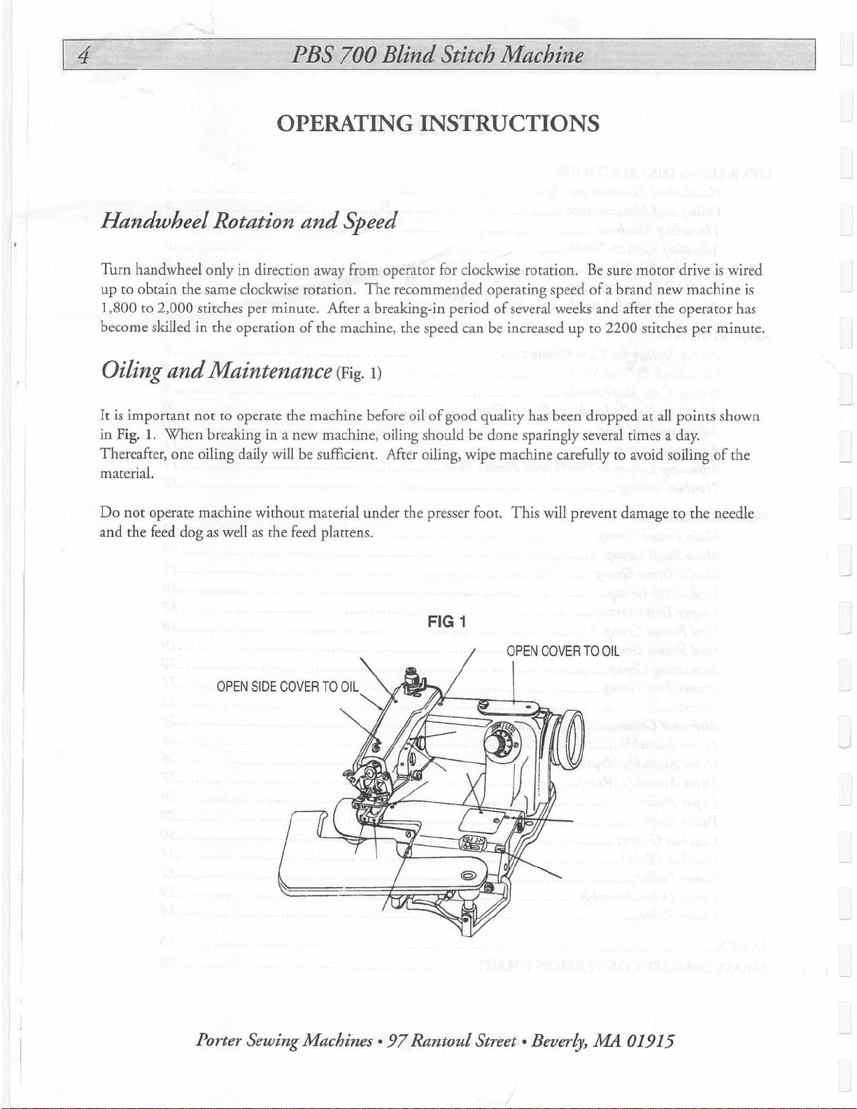
Oiling
It
is
in Fig.
Thereafter, one oiling daily will be sufficient.
material.
Do
not
and the feed dog
and
Maintenance (Fig. 1)
important
1.
operate machine without material under the presse
not
When
to operate the machine before oil
breaking in a new machine, oiling should be done sparingly several times a
as
well
as
and
of
the feed
Speed
The
recommended operating speed
Mter a breaking-in period
the machine, the speed can be increased up
of
good quality has been dropped at all points shown
Mter
oiling, wipe machine carefully to avoid soiling
plattens.
FIG 1
r foot.
of
several weeks and after the operator has
This
will prevent damage to the needle
Be
sure motor drive is wired
of
a brand new machine is
to
2200 stitches per minute.
day.
of
the
OPEN
SIDE COVER
TO
OIL
Porter Sewing Machines •
97
Rantoul
OPEN
COV
ER
Street • Beverly,
TO OIL
MA
01915

PBS
700
Blind
Stitch Machine
Threading Machine
Turn handwheel
thest left hand position.
Draw thread from spool
between two tension dis
0 , then down through needle
thread
To thread needle at
lifter, then hold thread between index finger
about 5 em
of
machine
(2
inch
point@,
cs
(F
ig.
2)
in
clockwise direction away from operator until needle lever reaches its fur -
on
thread stand
@, and pass it over rear thread guide
cl
amp hole 0 and pass it from
es)
past needle hole.
swing front plate
and
pass
out
and
it
through eyelet
of
way
thumb.
FIG2
of
@}
, through eyelet
the und
and
depress cylinder
End
of
thre
rear thread guide
of
erside
of
needle hole
out
of
ad
must be stub
0,
then slide
front thread guide
CD.
way with knee
not
feather edge.
it
Leave
Right
"''"'
~
Notlik•~
Wr
ong
Telephone
800-343-8138
or
508-922-2611 •
Fax
617-599-7081
6
PBS
700
Blind
Stitch Machine
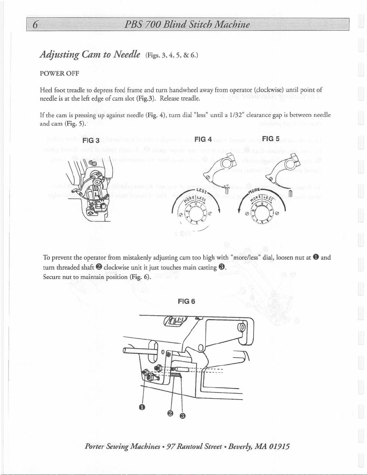
Adjusting
POWER
Heel foot treadle
needle
If
the cam
and cam (Fig. 5).
OFF
is
at the left edge
is
pressing up against needle (Fig. 4), turn dial"less" until a 1/32" clearance gap
Cam
FIG3
to
Needle (Figs.
to
depress feed frame and
of
cam slot (Fig.3). Release treadle.
·
3,
4, 5, & 6.)
turn
handwheel away from operator (clockwise) until
FIG4
FIG 5
point
of
is
between needle
To prevent the operator from mistakenly adjusting cam too high with "more/less" dial, loosen
turn threaded
Secure
nut
shaft@
to maintain position (Fig. 6).
clockwise
unit
it
just touches main casting@).
FIGS
nut
at 0
and
Porter Sewing Machines •
97
Rantoul
Street • Beverly,
.MA
01915

PBS
700
Blind
Stitch Machine
7
Replacing Needle
Turn handwheel away from operator (clockwise) until needle
of
reaches the end
Remove old or defective needle by loosening needle clamp screw
0.
Insert new needle into seat in needle clamp @ and needle
lever@)
(0.04") on the left end
screw
Turn handwheel slowly away from operator
ment
slightly on the needle guide groove
presser foot.
Always replace bent or bl
operation
as
far
0.
of
needle. The curved portion
of
its return stroke (extreme left hand position).
as
it will
machine.
(Fig.?)
go.
Make sure hole
of
presser foot 0 and tighten needle
of
needle
and
observe move-
of
the needle should bear
0 in the left hand
unt
needles.
They
affect the satisfactory
is
part
0-1.0
of
m/m
cl
amp
FlG7
0
Needle Recommendation
S
ize
#5-1/2
Regulating Stitch Length (Fig. 8)
Loosen sc
until desired numb er
larger the number
the
securely.
Number
Stitch Length (
NOTE:
area,
rews
0 in stitch regulating collar @
is
reached by indicator notch
by
the notch, the longer the stitch. The smaller @
num
ber by the notch, the shorter
on
Collar
SPI)
Due
to the changing thicknesses
an
end result
of
6-8 SPI will be satisfactory.
5
5
th
e stitch. Tighten screws 0
6
4.2 3.6
and
turn collar @
of
7
of
FIGS
eccentric.
The
9
3
0
material passing between the cam
and
shoe
Telephone 800-343-8138 or 508-922-2611
• Fax
617
-599-
708
1

8
PBS
700
Blind
Stitch Machine
ADJUSTMENTS
Proper Setting
Turn handwh
the right ha
passes over cam to other side
If
cam moves, make the foll
<D
. Bring the point
ing
sc
rewdriver in pla
needle in position with handwheel while pe
If
still
not
backward
& 0 before putting machine into operation.
eel
nd
edge
correct, readjust by loosening screw 0 again, change angle
as nee
for
Cam Connection
away from operator (clockwise) until needle
of
needle guide
owing adjustments: first open top cover plate and loosen screw 0
of
needle back to the rig
ce.
Move eccentric @ forward
ded and retighten screw
0,
Cam
of
presser foot opening@}.
0.
(Fig. 9)
is
on the down stroke.
@ should stop
ht
hand edge
to
rf
orming this operation. Tighten screw
When adju
FIG9
and
should not move until the point
of
needle guide 0 .
backward until cam is at the stop position, hold ing
of
sted satisfactorily, be sure to tighten both screws 0
Then
eccentric 0
When
loosen screw 0 , keep-
needle reaches
of
needle
on
eccentnc
0.
sl
ightly forward
or
0
Porter Sewing Machines •
97
Rantoul Street • Beverly,
A1A
01915

PBS
700
Blind
Stitch Machine
9
Setting
Remove cover
collar
position collar
(F
ig. 9A).
9B
Fig.
a clearance slot for the travel stroke
no interference contact after performing the off-set adjustment.
FIG9B
Cam Shaft Offset (Figs. 9, 9A, & 9B)
(F
ig.
9)
and
loosen screw @ on cam shaft drive
and
L.H. positioning collar (not shown). Loosen R.H.
@ and slide cam shaft
Then
secure both L.H. and R.H. collars.
shows the pivot shaft for the feed plattens.
to
dimension shown in
of
the cam. Be sure there in
The
shaft h
as
l
FIG9A
r
1/8"
OFFSET
DIMENSION
CAM
SHOE
0
Setting Cam Shaft Stroke (Fig. 9 & 9C)
When
adjust cam to
rib's forward movem
the point
be 5 m/m
of
needle
(13/64") between the center
ent
as
Telephone
is
at the cam, open window plat
shown
in
Fig. 9C.
800-343-8138 or 508-922-2611 • Fax 617-599-7081
........_
_____
e,
loosen screw @ and
of
needle and the end position
1--
of
GUIDE
FIG9C
ALIGNMENT
10
PBS
700
Blind
Stitch Machine
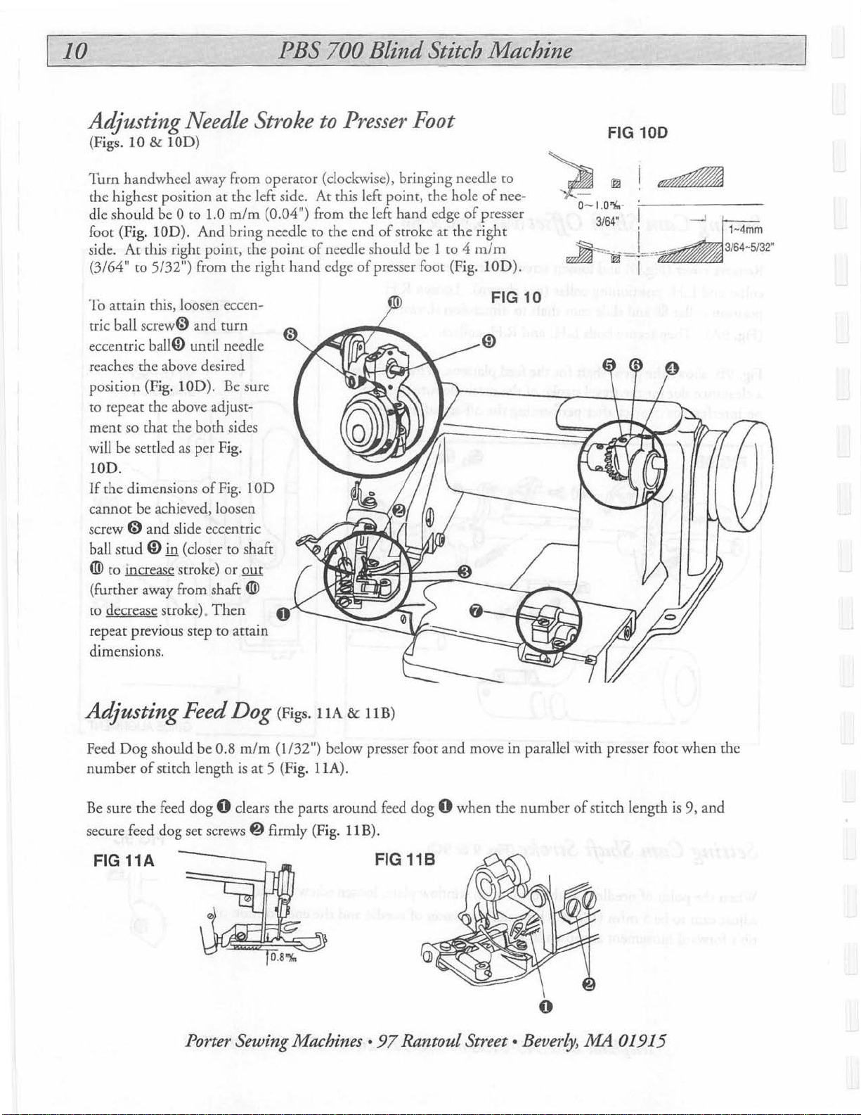
Adjusting Needle Stroke
(Figs. 10 & lOD)
Turn
handwheel away from
th
e highest position
dle should be
foot (Fig.
side.
(3/64"
To attain this, loosen eccentr
ic ball screw(;) and
ecce
reaches the above desired
position (Fig.
to
repeat the above adjustment
will be settled
lOD.
If
the dimensions
cannot
screw
ball
lOD).
At
this rig
to
5/32") from the right
ntric
ball@ until needle
so
that
the
be achieved, loosen
G)
and
stud
ID
in (closer to shaft
at
0
to
1.0
And
ht
point,
turn
lOD
).
both
as
per Fig.
of
Fig. 1
slide eccentric
® to mcrease stroke)
(further away from shaft ®
to
decrease stroke).
repeat previous step
dimensions.
Then
to
ope
rator (clockwise), bringing needle
the left side.
m/m
(0.04") from the left hand edge
bring needle
the
point
hand
Be
sure
sides
OD
or
out
0
attain
to
Presser Foot
At
this left point, the hole
to
the end
of
needle should be 1
edge
of
stroke
of
presser foot (Fig.
of
at
the right
to
4
ro
of
nee-
presser
m/m
lOD
FIG 10
~@
0- I.
).
O"l(.
3/
FIG
64"
100
·
Adjusting Feed Dog (Figs.
Feed
Dog
should be 0.8 m
number
Be sure the feed dog 0 clears the
secure feed
of
stit
dog
ch
length is
set
screws@
FIG 11A
Porter Sewing Machines •
/m
at
5 (Fig.
firmly (Fig.
IIA
&
liB)
(1/32") below presser foot and move
llA).
pans
around
liB).
feed
dog 0 whe
FIG
118
97
Rantoul Street • Beverly, .MA
n the
in
parallel with presser foot
number
of stitch length is 9, and
0
01915
when
the

PBS
700
Blind
Stitch Machine
11
Adjusting
Replaceme
Replacing Looper (Fig. 12A)
Loosen
looper in, the shoulder
der
sc
ofloop
Adjusting
and
Looper must clear the chaining finger 0 a
being
of
Make sure the distance between right hand side
rod folk pin
mally 104
The long prong
from the left
prong
12B).
Presser
ju
st above the needle abo
paper at point
of
Looper (Fig. 12A)
nt part
rew 0 to take
er rod
#2200B. [Generic Polished]
out
of
looper should
@)
at
pomt
Looper to Needle
Foot(Figs.
<D.
fi
and rear
m/m
(4-3/32") (Fig. 12A).
of
hand
the looper
face
the looper should
edge
of
needle hole when the long
is
on
the center
loope
r@.
Wh
en putting new
cou
ch the shoul-
0.
12A, 12B & 12C)
nd
clear needle,
ut
the thickn
of
looper rod ball @ is nor-
be 3 m/m
of
ess
the needle (Fig.
FIG 12A
of a sheet FIG
of
looper
(1/8")
128
If
looper touches needle
crews
s
by screwdriver.
stud
• and needle touches short prong
loosen
@)
point
Be
By
wise,
NOTE:
both
side and lower the other side.
Looper should clear chaining finger
point
loosening screws
In
eccentric stud
and does not have any play left or right. Secure by retightening screw
0 and turn the screwdriver slot in eccentric stud @
If
looper
@ clockwise.
nut
G) by wrench.
downward, which will clear short prong
4D
and raise looper at
certain to tighten
turning eccentric
it will raise
With
sides.
4@
case
of
the above adjustment, be sure that looper rod
or
eccentric stud ®, raise or lower looper
and
Move eccentric
0.
4D
is
0 (Figs. 12B & 12C).
or
presser foot at point
is
hitting needle, turn eccentric
If
looper touches presser foot
of
looper at
Then
turn looper rod
point.
all
screws after adjustments are made.
stud@
lower looper at points • and e .
4D.
This will get the desired clearance.
flush against looper and rod carrier
clockwise
Turning looper rod@), raise one
stud@
(Figs. 12A & 12C).
or
• and presser foot at
from left to right by
@,
at
point
point
at
point
of
looper
counterclock-
loosen
C8,
at
on
~
FIG 12C
Telephone 800-343-8138 or 508-922-2611 • Fax
617
-599-7081

12
PBS
700
Blind
Stitch Machine
Troubleshooting
G
Thread
break
Stitches
skip
Cause
Inspection
L
I
Poor-quaHty
Too
Needle insta.ll
Needle, l
foot,
have defective replace
Thread
or weak
Wrong threading
Needlt
Needle point defective
Looper
thread
thin
needle
ed
incorrectly
ooper,
presser
thre
ad passage
tensi
on
too
strong
installed incorrectly
defective
Thread
Thr
ead tension
Looper
quality
blunt
control
or
broken
Use thread
quality
Replace with a thicker
needle
Smooth
•nd
Adjust to
tension
Replace
needle
Smooth
and
repla.ce looper
·~~·
of
good
with
sandpa
polish
with
buff,
correct
with •
good
with
sandpaper
polish with
huff,
per
or
thread
or
1
··
~1
Relative
of
ooper
c.am
or
and
thin nee
cop
dog
needle
clearance betWeen
looper
dle
hit nee dle
bt:tween
roo
great
tension t
installed
or
worn
Needle
Uneven
Stitches
or
loose
Improper
break
stitch
too
feeding
tight
l
needle
Too
Needle inStalled incorrectly
Looper
Clearance
and
Thread
orwuk
Feed
incorrectly
Porter Sewing Machines •
and
are wrong looper
needle
~int
oo strong
out
97
Rantoul
Timing
between
Direction
needl•
Clearance
and
looper
Thread
or
clearance
need
le
and
Rep
lace with a
needle
and
position
of
between
needle
ten
sion
contro
l
Adjust to
tension
Street • Beverly, .MA
correct
thic
ker
thread
01915

Ref#
1
2 .
3
4
5
6
7 .
8 .
9
10
11
12
13
Part#
....
.700000 . .Side
.700010.
.700020. . .Screw,
...
700030
.....
700040
..
700050
700060
.700070
.....
700080
.700090 . .Nut,
..
700095 . .Pin,
..
700100
....
700110
Description
.Washer,
. . .
.Screw,
. . . .
Thread
..
Thread
.Disc.
.....
Post, Thr
. . .
.Spring,
.....
Screw,
....
Tube,
Cover
Clamp
Side Cove
Guard
Tens
Guide
Thread
ead
Tension
Tension
Spring
Feed
Oil.
PBS
Assembly
Screw ........
. . . . . . 1
ion
Regulating
. .
Tens
Tension
. .
. . . .
..
Lever
. .
700
r....
......
Assy •....
..................
ion
. . . . . . . . . • • .
. . . . . 1
................
. . . . .
.. ..
. .
Plate
Blind
.......
..
Qty
.....
. 1
. 1
. • . 1
1
1
.2
....
1
1
. 1
. 1
..
1
Stitch Machine
Ref # Part
14
....
15
16
17
. .
18 ....
19 . .700170
20 . .700180
21
22
....
23
. .
24
25 . 700230
#
700120..
..
700130
.700
140 . .Screw,
700150
700160
.700190
700200..
700210
700220 . Thread
Descr
.Wick,
.Screw,
.....
Pin,
.... Screw,
. . .
Plate
. .
.Screw,
.....
Screw,
.Washer,
. .
.Screw,
.....
Screw, Thread
Presser
MAIN FRAME GROUP
ipti
on
Oil
Set
Set
Set
, T
op
Cove
Top
Bridge
Clamp
Clamp . .. . .. . ..
Guide
. . . . ..
. .
.....
.............
. . . . . . . . . . . . . . . . . 1
Foo
t . . . . . .
. . . . • •. .
r . . . . . . . . . . . . . . . . . 1
Cover
. . . . . . . . . . • • • . 1
Mig.
Screw
.. ..
Guide
. .
. . . . . . . . 1
.. ..
..
..
.
. . . . .1
.....
........
. . . 2
........
13
Qty
1
2
.1
1
1
.1
Telephone
800-343-8138 or 508-922-2611 •
Fax
617
-599-7081

14
MAIN SHAFT GROUP
Ref#
1
2 . .
3 .
4
5
6 .
7 . .
8
9
10
Part#
....
700240
.....
.700250
..700260
.....
700270
.....
700280
.700290 . .Needle
.70
.....
700310
.....
700320
..
700330
. .
..
....
....
0300 . .Screw
...
.....
Main
Rib
Screw
Screw
Screw, Clamp
Guard
Screw
.Screw
PBS
Description
Shaft
.. . ..
. . . . .
Connection Lever & Eccentric
Eccentr
ic
. .
For
Stud
. .
. . . . . . . .
Connection
. • . . . . . . .
.. ..
....
Ass'y
. .
..
..
..
. . . . .
................
1-----{6
700
Blind
Ass
.............
.............
............
........
'y
Stitch Machine
Oty
Ref # Part
11
..
12
13
14
15
16
17
18
19
700620
..
700610
....
700360
....
700370
..
700380
..
700390
....
700400
....
700410
.700030
..
.1
1
2
.1
.1
1
2
.1
.2
1
#
....
..... Scr
...
. .
..... Scr
Description
..
Stitch
Collar
..
Set
Screw
Collar
Ass'y
ew
Handwheel
.. Scr
ew
.Pulley
Ass'y
ew
..
Screw .....
. . .
....................
. . . .
. . . . . . .
.. ..
.. .. . ..
.....
. . . • • . • .
.. .. .. . ..
..
..........
. . . . . . .
......................
............
. . . .
.........
.............
. • . . .
Qty
1
2
.1
.1
1
3
.1
.1
1
,-@
I
2
16
Porter Sewing Machines •
97
Rantoul
Street • Beverly, A1A
01915

Ref#
1
2
3 .
4 .
5
6
Part#
.... .700430 .....
....
700440
700450
7004
60 ..... Leve
....
.700470 ..... Screw
....
.700480 . .Screw
Description
Need
.. Clamp
...
Pin
PBS
le
Lever
Ass'y
. .
...................
..
.. .
.. .. .. ..
r . . . . . . . . . . . . . .1
700
.. .. ..
................
Blind
.......
. . . 1 9 .
•.• ......
Qty
1
1 8 .
. 1 11
1
Stitch Machine
Ref # Part
....
7 .
10
....
....
#
700490
.700160
..700510
7005
20
700530
Description
.Collar
.Screw
....
Shaft
..... Scre
..
PSM550
w . . . . . ..
NEEDLE DRIVE GROUP
Qty
Ass'y
. . . . . . . . . . . . . . . . . 1
. . . . . . . . . . . . . . . . . . . . . . .
.. .. . .. .. ..
. . ..
. . . . 1
...
.....
..........
....
..
@--f
15
.2
1
1
Telephone
800
-343-8138 or 508-922-2611 • Fax 61 7-599-7081

16
FEED DRIVE GROUP
Ref#
1 . .
2 . . .
3
4
5 . .
6 .
Part#
.700540
700550
...
.700560
...
.700570
..700580 . .Set
700100
.....
.....
. .
. .
Description
Feed
Lever & Stitch
Feed
Rocker
Feed
Lever
Screw-Le
.Thrust
Collar
Screw
PBS
Collar
Ass
'y
Plate
. . . . .
verPiate..
Ass'y
700
. .
..
......
. • . •
Blind
Ass'y
........
...........
. . .
............
.......
.....
Stitch Machine
Qty
Ref # Part
...
700590 .Feeder
7
1
.....
700600
8
1
9
...
.1
.1
1
2
700610
10 .700620
11
. .
700630
#
Description
..... Feeder
.....
Set
.Stitch
. .
.Feed
. . . . . . . . .
Screw
Screws
Collar
Leve
r . . . . • . . • .
. . . . . . . .2
. . . . . . . . . . . . . . . . . .
...................
Qty
.....
.
...
.1
2
. 1
.1
Porter Sewing Machines •
97
Rantoul
Street • Beverly,
.MA
01915

Ref#
1
2 . .
3 .
4
5 .
6 . .
7
8
9
Part
#
..... 700640
'Z.00650
..700660 . .Collar
.....
700580
....
700670
.700680
..
700690
.....
7007
00
.....
700710 ... ..
PBS
Description
. . .Looper . . . . . . . 1
-. .
.Stud,
Looper
Adjustment
Ass'y
........................
.....
Set
Screw
.......................
..... Loo
.....
per
. .Fo
rk
. .Pin .
Screw
Nut
Rod Fork,
. . . . . . . . . 1
..
.....................
...........................
. . . . . 1
700
. . . .. . . . 1
Sleeve & Stud
Blind
Qty
Ass'y
Stitch Machine
1
1
. 1
1
1
Ref#
1 0 . .
11
12
13
14
15 . .70075
16
17
Part#
700720
. .
700730
....
700770
....
700780
.7007
40 . ..Looper
....
700760 ..... Looper Rod,
....
70076
. .
. .
....
. .
0 . .
5 ..
...
LOOPER DRIVE GROUP
Description
.Looper
Rod
Sleeve
Ass'y
.Scre
w . . . . . . . . . . . .
Stud . .. . ..
.Nut
.Screw
. . . . . .
Rod & Ca
. .
Screw
. . . . . . .1
. .
.. . ..
............
Fork & Carrier
.. . .. .. . ..
rrier Ass
....•.........
'y
Ass'y
Qty
. . . . 1
. 1
.. . .1
.1
.
.1
..........
. . . . .
1
.1
1
17
©--
---
------
I
'
~
Telephone
800
-343-
8138
or 508-922-2611 • Fax 617-599-7081

.-------------
FEED FRAME GROUP 1
Ref#
2 .
3 . . .
4
5 .
6 .
7
8
9 .
10 . 700830. . .Nut
11 ....
12
13
14 . 700880
.
.....
.....
.....
....
Part#
700740
700750
..
700760
700770
700780
700790
70080
700810
700820
700840
700850
700860
.....
.....
. .
. .
0 .
.....
. .
. .
.....
....
. .
---------------------------
Description
..
Rib
Shaft
Assy
..
Feed
Frame
Collar
Ass'y
Set
Screw
............
.Rib
Shaft
Crank
.Screw
..Plate,
Screw, Plate
.Post,
.Platten,
Screw, Platten
Nut
.Screw, Cylinder
. . . . • . • . • • . 1
Window
Spring
. . .
L.H..
..................
PBS
...............
Ass'y
. . . . 1
Ass'y
..
..
.. . .. .. .. . ..
. . . . . . . . . . . 1
700
. . . . . . . . . . . ... 1
. • . • . . . • . 1
.. .. .. . .. ..
. • . • . • . .
..
..........
.. .
. .
..
. . .
............
Blind
Qty
.
.....
. . 1
.2
..
..
.2
...
. 3
1
1
1
1
1
-
--------------------------------~
Stitch Machine 18
Ref#
Part#
15 ....
700890
16
..
700890
17 . .700900
18 . .700910 . .Stud
19
....
700030
20
....
700920
21 . .700930 . .Spri
22 . .700940
23
....
700950
24
...
.700960
25 . .9009
26 . .700970 . .Cylinder
27
....
70
700980
.....
Nut, Platten
.....
Bkt,
. .
Bkt, R.H.
.....
Set
.....
Spacer ...
. .
Screw, Limit
.....
Post
.....
Platten,
. .
Screw,
.....
Shaft,
Description
L.H. Platten
Screw
ng
..
Lock
....................
...............
Platten
. . . . . . . . . . 1
.............. . .
..............
. . .
..
..
R.H
.....
Frame
. . 1
Rocker
. . . . . . . 1
..
. • • .
..
. . • . . • . .
..
.. ..
. . . . .
....
...
. . . • . • .. . . 1
.
....
.....
..........
. • . .
...........
Qty
. 1
..
..
..1
. 1
2
1
1
4
2
1
I
I
Porter Sewing Machines •
97
Rantoul
Street • Beverly,
..Mil
01915

Ref#
1
2
3 .
4 . . .
Part#
..... 700990
.....
701000
700860 . .Nut, Ret'ng
7
01010
PBS
Description
..... Spring Link Ass'y . 1 5
.. Pin
. . . .
. .
....................
.... Screw,
Link .. . ..
..
.. .. .. . ..
700
..
Blind
..
RE
OF
Stitch Machine
Qty
..
1 6
1 7
. 1
AR WA
MAIN FRAME
Ref# Part
..
701020
...
..
701030
...
..
701040 . .Key
LL
#
~
.....
.....
FEED FRAME GROUP 2
Des
cript
ion
Nut,
Spring
........
Main
Spring
.
.
/\
. . •
..
. • . .
...........
19
Qty
1
.1
1
~
J
I
I
,~
/)
<,
/'
..........
/
·
~
@
'
'-....
'·-
/
/
IJ
MAIN
FRAME
Telep
hone 800-343-8138 or 508-922-2611 • Fax
--
617
-599-7081

20
REGULATING GROUP
Ref#
1
2 .
3 .
4 .
5
6 . .
Part#
..... 701050
..701060
..701070
..701080 . .Spring
.....
.7
701
090
01100
.....
.....
..
..... Regulator
..... Screw,
Regulating Fork
Push
Pin
PBS 700 Bli
Description
Rod
Ass'y
.. ..
..
.
..
............
. . . . . .
Ass'y
. . . .
Regulator....... .. . • . • • .
.. ..
. . • .
.
.........
.......
nd Stitch Machine
Qty
Ref
# Part # Description
.
.1
7 .
.1
.1
.2
1
1
..701110
8 .
.701120
9 . .
.701130 . .Screw
10
....
11
.701150
12
..
701160 . .Pin
701140
.....
. .
.....
.....
Dial & Ratchet
Dial
Plate
Ass'y
Shoe
..
. . .
Screw
...........................
. . . .
Ass'y
.................
..................
................
. .
..
....
..
Qt
y
1
1
.1
1
1
1
Porter Sewing Machines •
97
Rantoul
Street
• Bever
ly,
A1A
01915

Ref#
Part#
Description
PBS
700
Blind
Qty
Stitch Machine
Ref#
Part
#
Description
21
PRESSER FOOT GROUP
Qty
700190
700810
2 .
.....
701170 . ..
3
.....
701180 . .Screw
4
701190 . .S
5 .
6 .
.701200 . .Spring
7
.....
701210
.....
701220
8
9 . . .
701230 . .Shoe
10
..
701240
11
....
701250 .....
12 ....
701260
13
. .
700770
14
. .
701270 . .Nee
.Screw
.Screw ............................
.Screw
.....
.Sp
..
....
.Screw
..
pring
......
Shoe
Pin
ring
. . .
Screw
.. .. . ..
Anchor
Guide
. . . . .
. .
dle
Guide
. . . . ....
..
..
.. .. ..
. . . • . . 1
. . . . . 1
. • . . • . . . ....
......................
..
..
..
.. ..
.. ..
..
..
..
. . . . . . . . . . . . . . . . .
. . . . . . . . . . . . . . . . .
. . • . .
. . .
..
...........
....
....
....
2
15
2
16
17 . 701300.
18 . 701310.
1
19
1
20
.1
21 . 700200.
.1
22 . 701330.
.1
23
1
24
.1
25
.1
26 . 701370
.1
27
1
28
....
701280 ..... Screw
....
....
....
....
....
.701360
....
....
701290
701320
700210.
701340
701350
701380
701390
...
....
.....
.....
...
. .
.....
.....
.. . ..
.. .. ..
Screw
. . . 1
.Bushing
.Screw
.Wedge............
..Screw
..Washer
..Presser
.Screw
..........................
. .
..
Foot
......................
Screw
. ..
.. ..
Screw
Washer
Bridge
Chain
. .
....
..........
. . . . . . . . . . . . . . . . . . . . 1
Off
Pin
. . . . . . 1
...........
. .
..
. .
. . . . . .
.
..
. • .
..
......
..
..
.. ..
. . . .
.......
.....
........
. . . . . . . 1
..
1
1
.1
.1
1
1
.1
1
1
1
r
Te
lephone 800-343-8138 or 508-922-2611 •
Fax
617-599-7081

22
COVERS
Ref#
1
2
3 .
4 .
5
6
7
8 .
Part#
..
. .
BHCS440X1/4
.....
BSC-10
.BSC-11 .......
.BSC
-1 . .
.. .BSC
..... BSC-9
-7 . .
.
BSC-4
.BS
P-20
Description
.Screw
......
Bracket
Rig
Cover, Sh
..
Hand
Wheel Cov
..
Large
Shield
...... Top Right
....
....
Small
Shield
. .
.Gear
Box
PBS
.
ht
aft-Rear
Pulley ...............
Belt
Pulley
Cover
700
.. .. .. ..
. . . . .. 1
. . . . 1
er
. . . . . . . . . . . 1
Guard.
. .
. . . . . . . . . . . . . . 1
Blind
Qty
..
.. 4 9 . . .
. • .1
.3
Stitch Machine
Ref # Part
10
11
12
1
13
14
15
16
....
. .
. .
. .
....
#
BSC-3
BSC-2 ........ Bracket Pulley Cov
BSC-8
BHCS6-32X1
BHCS6-32X3/8 .
BSC-6 .......
..
BSC-5
..
SHCS6-32X
........
....... Left
Description
.Guard-Ma
Left
Shield
/4 .Scr
ew
Screw
Bottom Right Belt
Bel
1/4 .Screw
in
Shaft
er
Belt
.. . ..
. . . 1
........................
. . . .
t Br
acket
.....
....
Guard
..
................
......
. . . . 1
. .
..
. . 1
. 1
...
Qty
1
.4
. 5
2
Porter Sewing Machines •
97
Rantoul Street • Beverly,
.MA
01915

ALTERNATE COVER
PBS
700 Blind Stitch Machine
23
Ref#
1
2
Part#
..... BSC-30
.TS-1" . Taping
Description
..
Bii
ndsti
tch
Cover
Scr
ews
. • ..
Qt
. . 1
......
2
y
Telephone 800-343-8138 or 508-922-2611 • Fax 617-599-7081

24
PULLER ASSEMBLY
Ref#
1 .
2 . .
3 .
4
5
6 .
7
8
9
10
Part#
....
BS-2
09
.........
1611A
.C0-401-DOO . .Air
.....
93191
..... BSP
.....
.....
-17
.........
..PBS7
00-
EGH
..
BSP
-22
BSP-
03 . .
BSP
-04
......... Block
..
SHCS8-32X1
PBS 700 Blind Stitch
Description
Spacer
....... 0-30PSIGuage
. .
.Bracket
Adj.
.... Cloth Guide . .. ..
. .
.Shaft
.Support
/2 ...
Screw
. . . . . . . 1
Regulator
Universal Jo
. .
..................
. . . . .
....................
. . .
.. . ..
.. .. ..
...........
int
. . . 1
.. ..
..
. . 1
......
..
. . .
Qty
...
1
1
2
1
1
.2
.2
Machine
Ref # Part
11
...
3011
12
..
BS-233
13
...
5283
14
....
BS-204
15
..
BS-317
16
.. 3/8-16X2-1
17
..
BSP-2
18
.. .BSP-25
19
.. SHCS8-32X3
20
..
BSP-02
#
...
........
. .
. . .
......
...
.........
/2
..
1 . .
......... Pulley
/4
...
. .
Description
Yoke
.........................
Yoke
Bracket
Shaft
..............
Top
Roller.
Yoke
Support
Cloth
Plate
Stud
.Shaft
Screw
.Housing
. . . . . . 1
. . 1
....................
. .....................
. . . . 1
. . . . 11
. . . . . . . . . . . . . . . . .
......................
Qty
1
1
1
1
.2
1
Porter Sewing Machines •
97
Rantoul
Street • Beverly,
.l\1A
01915

Ref#
21
22 . .BSP-06
23
24
25 .FB68·
26
27
28
29
30 ...
Part#
..
375RPP5
.... BSP-24
.. ..
SC37
3-1/4
..
BSP-05
....
HN3
/8·
. .
.SS1/4·28X3/8
..
BS-206
SHCS10·32X1-1
. . ..
. . . .
....
. . . .
. . .
. .
16
.......
. .
PBS
Descri
lion at
.Belt
. .
Shaf
t . . . . . . . . . . . . . . . . . . . . . . . 1
Pulley
. . . . . . . .
.Collar
. . . . . . . .
Bea
ring
. . . .
...
Universal
Nut
.Screw
.Stiffener
/4
Screw
Joint
. . . . . . . . . . .
. . . . . . .
..............
700
..............
.............
. . . . . . . . . . .
. .
Blind
.....
............
......... 2
Stitch Machine
Ref # Part
1
31
....
32 . .SHCS10-32X1
.. 4 33 . .BSP-10
.2
34
....
6
35 ....
1
36 . .Exp
.3
37
.2
38
....
1
#
BS-216
SHCS1/4·20X1·3/4Screw
FU1/4-Biack
1/8X5
.BS
P-01 . ..
BS207
..
......
/8 .
.. ..
Descri
tion
..
Adapter
/2
..
Screw
Mounting
..
Washer
.Pin
...
Support . .. .. .. ..
..
.Support
Mtg
. .
Bracket
. . . .2
. . . .
..
Bracket.
..................
. . . . . . . . . 1
.................
.. ..
. . . . .1
.
......
•
.......
25
at
1
.4
4
2
.1
Telephone
800-343-8138
or
508-922-2611 • Fax 617-599-7081

26
DRIVE ASSEMBLY (FRONT)
Ref
# Part#
1 . .
.SHCS8-32X3
..
BSP-14
2 .
..... BSP-15
3
.....
BSP-21
4
..BSP-19
5 .
6 . .
.450RPP5 . .Belt
.....
425RPP5 . .Belt
7
8
.....
BS-500
..0231-1
9 .
10
..
BSP-24
........
/8 .
. .
.......
...
.
Desc
Screws
.Base
.Adjustment
Pulley
Shaft
Yoke
.Rod
Clevis
.Pulley
PBS
ript
ion
.............
. . . . .
Plate
. . . . . . . . . . . . . .
.........................
. .
. . . o
.........
......................
. . . . .
700
..........
. . . .1
..
o • • o .1
..
Blind
Qty
.
.4
.. ..
1
.4
1
....
1
.1
1
....
.4
Stitch Machine
Ref#
11 ....
12
13
14 .BSP-13
15
16
17 . .6072K21
18 . .FW1/4-Biack
19
20 ...
Part#
BHCS8-32X3
....
BSP-18
.Y
A-18
-3/8 .
....
FBG8-3-1
....
SHCS8-32X1-1
....
BS-501
BSP-16 .......
/8
....
/4
. 1/4
. . .
Description
.Screws
..
Shaft
.Spur Gear ......................
.Side
.Bearing
/2
Screw
.Washer
Pin
Nut
. . . . . . . . 2
U-Joint
Plate
28 Male
Yoke
Plate
..........
Assy
..................
.. . ..
. . • • . . • . ..2
Ball
Joint
.. ..
...
..
..
........
........ 2
. .. .
. .
. . .
....
. . .2
..
Qty
.4
..
..
1
2
1
1
1
Porter Sewing Machines •
97
Rantoul
Street • Beverly,
..MA
01915

PBS
700
Blind
Stitch Machine
DRIVE ASSEMBLY (REAR)
27
Ref#
1
2 .
3 .
4 . .
5
6 .
7 .
8 .
9
10
11
12
Part#
.....
GR3070037 . .Belt
.3007
..30320 . ..
.BS-244
.....
SHCS8-32X3
..BS-213
.41-V
.BS-304
....
BS-306
.SHCS8-32X3/8
.PC5-4
..
HN10-32
. .
....
........
/4
. .
. .
.......
. . .
.
......
Description
.Rod
Pulley
Drive
.Screw
.Pulley
...
Belt
Ecc. Drive
..
Ecc.
.Screw
..Washer
Nut.....
End
..
..
.. ..
.. . .. ..
..
.. .. . .. ..
Flange
. .
..
..
..
.. .. . ..
Hub
Dri
ve
Retainer
. .
...................
.. .. .. .. ..
. . . . . . . 1
. . . . . 1
.. .. . ..
.. ..
..
. . .
. . . . .
. .
.
Qty
....
.. ..
. . . . 1
......
....
.. ..
..
......
Ref # Part
1
13
. 1
14 . .2993
15 . .K11
16
. 3
17
.1
18 . .1412
.1
19
.1
20
.. 1
21
.4
22 . .38
.1
23 . .BS-306
24
#
. .
.HN1/4
-28
M40740080
....
BHCS10-32X1
....
XCK-22
.
. .
FHCS8-32X
....
BS-256
....
BS-258
KLL
....
HHCS10-32X1
.
. .
. .
1-1
.......
. .
.
........
Description
.Nut
. . . . . . . . . . . . . . . . . .
.Push
Rod..
.Positioner
/4
Screw.
.Synchronizer
.Positioner
/4
Screw
.. ..
Handwheel
.Handwheel
..
Bearing
Bus
hing
..
Screw
. . . . . .
..
....
_ . . . . 1
Holder
. .
........
Positioner..
Adapter
. .
. .
Adapter
.. .. .. . .. ..
..
. . . . 1
.......
. . . . . 1
...........
. . . . . . . . . . .
. . . .
...
......
Qty
.2
..
1
1
. 1
.3
1
.1
.1
1
Telephone 800-343-8138 or 508-922-2611 • Fax 617-599-7081

28
UPPER PULLER
Ref#
1 . .
2 . .
3
4
5 . .
6 . .
7
8
9 . .
10
11 ....
Part#
.BSP-06
.BSP-24
.....
BSP-03 . ..
.....
SHCS8-32X5
.3/8-16X2-1/2
.375RPP5-9
.....
BSP-10..
..
...
HN3
.BSP
..
BSP-25
BS-405
/8-16
-21
Description
. .
. .
. .
/8
. .
......
..
..
..
PBS 700 Blind Stitch Machine
.Shaft
..........................
.Pulley
.Su
pport
. . . . . . .
.Screw
.Stud
.Mounting
. . . . . . . . . . . • . .
. . . . .
Belt
. . . . . . . . . . . . . . . 1
Bracket
Nut........
Pulley
Shaft
Pulley
Spacer
. . . .
. .
.....................
. . . .
...
. . . .
. . . . . . .
.............
. . . . . . . . . . . .
.........
Qty
Ref # Part
1
12
4
13
.1
14
.2
15
1
16
17
.1
18
.3
19
1
20 .BSP-02
.. 4 21
.2
22
#
..
BS-5283
....
BS-233 ....
..
3011
..
BS-204
.BSP-04. . .. Block
....
SHCS8-32X1
....
SHCS8-32X1-1/2Screw
.BSP-05
....
SC37
....
FB683X1
. .
....
..........
. . .
/2
. . . .
. . . .
. . .
/4
.....
Description
.Roller
. . 1
Pin
Yoke
..........................
Yoke
Support
.Screw
Universal
Housing
.Collar
Bearing
...................
. . . • . • . • . • . .2
. • . • . .
................
Joint
. . . . . . . . . . . . . . . . .
. . 1
. . .
. . . . . . . . .
..
. . . .
. 1
.........
......
Qty
1
1
.2
2
.1
.2
2
Porter Sewing Machines •
97
Rantoul
Street • Beverly,
.MA
01915

Ref#
Part#
Description
PBS
700
Blind
Qty
Stitch Machine
Ref # Part
#
Description
29
PULLER SHAFT
Qty
.BSP-16
...
FW1
2
3
.....
BSP
4
....
BSP-22
5 . .
.BSP-15 . .Adj.
.
BSP-17 ...
6 . .
...
..
BSP-18
7
/4
-14
...
....
..
....
.Nut
Plate
Block
Base
Shaft
Plate
U-Joint
Shaft
........................
Spacer
..
..
..
..
. . . .
. . . . . . . .
. .
. .
....................
. . . . . . . . . . . . . . 1
. . . . . . . . . . . 1
........
1 8
.1
.1
1
1
.BSP-
9
.BSP-20
10
...
YA-18-3
11
....
BSP-19 . .Shaft
12
.BSP-24
13 . .BSP-11 . .Side
12
/8
...
. .
..
Side
Plate Left. . ................
.Cover
. . . . . . . . . . . . . . . . . . .
Spur
Gear
. . . . . . .
. . . . .. . • .
Pulley
. . . .
Plate
Right
.. ..
. . . . . .
..
................
..
..
. . 1
....
1
.1
.2
1
4
Telephone 800-343-8
138
or 508-922-2611 •
Fax
617-599-7081

30
PBS
700
Blind
Stitch Machine
GEARBOX
Ref# Part#
1
.. . .450APP5·9
2
.....
GR3070037
3
..
6C32H3712
..
HN1/4X28
4
.RCB061014FS
5 . .
6
.....
BSP-24
..425RPP5
7 .
..BSP-23
8 .
.
CS5·4
9 . .
10
....
CD3·5 . .. . .. .Washer
11
..
SS-2·
..
. . .Collar.
7 4 . . . .
(FRONT)
Description
.Belt
....
Belt
...
Pulley
. .
Nut . .. .. . .. .................
.Clutch
..
..
.Pulley
·9
....
Belt
.
.Shaft
..
Spacer
. .
. . . . . 1
.. .. .. . .. ..
Bearing
.. .. . .. ..
..........................
. . . . . . . .1
. . .
..
. . . ........
. .
.........
. . . . 1
..........
• . . .
Qty
1
1
2
.2
.1
1
2
.2
Ref # Part
12
....
SS1/4·28X1
13
....
BH68
14
..
3006
15
..
CS5-4
16
....
CD3·5
17
....
BS-207
18
.87
·43
19
.BS
-303
20
....
RCB061014FS
21
....
BS-228
22 . .60
72K31
#
.........
.
. . .
. . . . ...
. .
. .
........
Description
/4
..
Screw
Bea
.Clutch
.Co
llar
.Wash
Suppo
.Bearing
.Bushing
.Clutch
Collar
... Female
. .
rin
g . . . . . . . .
Arm
.....................
• • . .
...
er
rt
. . . . . . . . • . • • . . . .1
...........
. . .
Bea
rin
g.
. . . . . .2
..
.. ..
. . . . . . .1
Ball Joi
nt
.......
....
.........
..
...........
.........
. . .
.......
Qty
.2
.1
1
2
.2
2
1
. 1
Porter Sewzng Machines •
97
Rantoul
Street • Beverly,
..MA
01915

Ref#
1
2
3 .
4
5
6
7 .
8
9 . .
10
11 . .BS-306
Part#
...
BS-258
....
FHCS8
.1412
.HN1/4-28
...
2993
. . . .
.....
BHCS10-32X1
..HHCS10-32X1
..
38KLL
.HN1
0-32
....
PC5
-4 . . ..
-32X
1-1/4
.........
.. . .Nut
. . . .
. .
.......
Description
..
Handw
heel
.Screw
Positioner
..
Push
Rod
/4
.Screw
. . . . . . .
... Scr
ew
.B
earing
.Nut
. . . . . .
.Washer
Bus
hing
PBS
Adaptor
. . .
Adaptor... .
.. .. ..
. . . . . . . . . . . . 1
.
. . . . . . .
. . . . . . . . . . 1
..
..
.
.. ..
..
.. .. . .. ..
700
Blind
. . . . . . .
.. ..
..
..
. • . . 1
. . . 1
....
..
...
Stitch Machine
Qty
Ref # Part
.1
12
...
BS-305
.3
13
....
BS-304
1
14
..
BS-213
2
15
..
BS-2
16 . ..SHCS8-32X3/4
17
....
3032U
18
. .
.3007
1
19
..
GR3070037
.1
20
.BS-281
1
21
....
HHCS1
22 . ..SHCS8-32X7/8
#
44
. . . . . . .
Description
..
........
. . . . .
. .
. .
0-32X1 ...
.
Ecc. Dri
. .
Ecc. Dri
Pulley . ..
.Dirve
Flange
.Screw
... Pulley
Rod
End
.. Belt
..
Hand
Wheel Shaft
Screw
..
Screw
GEARBOX (REAR)
ve
Retainer . ..
ve
Hub . .. .. ..
..
..
. . . • . . .
..
..
. . . . . . . . . . .
.
..
.. . .. ..
. . . .
..
..
. . . .
. .
..
.. . ..
..
.. ..
. . . 1
....
..
..
. . . . . . . 1
.
Qty
.1
..
.. 1
. ..4
.1
.1
....
..
31
1
1
1
4
Telephone
800-343-8138 or 508-922-2611 •
Fax
617-599-7081

32
LOWER PULLER
Ref#
1 . .
2 .
3 . .
4
5 .
6 . .
7 . .
8
9
10
11 . .122NR
.....
.....
Part#
.5284
.BS
.S
BS
..BS
SS1
exp1
400
..
BS
.BS
S1/4
316
203
234
/4 28x3
/8x
Rpp 5-9 .
232
238
. . . . . . .
.......
28x3/8
. .
. .. .
/8
5/8
. . .
......
. .
Description
.Gro
oved
Lower
Roller
.Screws
..
..
.Yoke
..
. . . . . . . .
Yoke
Bracket
Yoke Pivot
Screws
Pin
..
.. ..
Tim
ing
Belt.
. . . . . . . . . . . . . . 1
Shaft
Air
Cylinder
PBS 700 Blind Stitch
Oty
Roller
. . . . . . . . . . . . . 1
Stripper
.. . ..
Shaft . ..
. . . •
. ..
. . . . •
.. ..
..
..
. . .
..
............
.....
..
..
. • .
..
..........
.......
. . 1
.. . ..
.. ..
........
1
6
.
.1
.1
6
1
1
1
Machine
Ref # Part
12
...
13
14
15
...
16
.. ..
17
. .
18
19
....
20 . ..
21 . .SHCS
#
BSp25 ....
..
SHCS 1/4x1
.BS
201
.BS
202
BS
233
3011
.BSp
25
BS 239 . . .Sha
BS
405
. .
.
..
.........
. .
..
. .
8·32x3
Description
. Pulley.
...
Screws.
.Mou
nting
.Cylinder
Yoke
Bracket
Yoke
. .
..
Pulley
.. ..
ft
.. . ..
Spacer
/8
Screws
.............
. .
Bracket
Suppo
Shaft
• . . . . . •
..
. . .
rt
. . . . 1
..
..
....
..
..
.
.. . ..
.. .. ..
.
....
........
..
..
. . . . 1
.........
......
..
... .. .
Oty
...
...
.
....
..2
. 2
1
1
4
.1
.2
2
Porter Sewing Machines •
97
Rantoul
Street • Beverly,
.M:A
01915

Ref#
Part#
Description
PBS
700
Blind Stitch Machine
Qty
Ref # Part
33
LOWER DRIVE ASSEMBLY
#
Description
Qty
1 ..
2
..
...
..
3
4
.....
5 ..
6 . .
7
..... B7-
8
.....
9 ..
10
..
11 ....
BS-236
BS-237
BS-235
. . . . . .
BSP-25
. .
CS53
.BS-247
38
. . .
BS-254
........ Shaft
6044K3
1 .
HN3/8X16
BS-249
. .
Universal
. .
Shaft
.Universal
..... Pulley
. .
.Co
. . . .Sh
.Bearing
.Knob
.Nut
. .
.Pulley Plate
Joint
..........
. . . . .
Joint
. . . . . . . . . . . .
llar. . . . . . . . . . . . . . . . . . . . . .
aft
Support
..........................
. .
. . .
. • . . . .
. . . . . . .
..
.. ..
. .. .. ..
. . . . . .
..
......
. .
...........
.. .. ..
1
12
....
BS-246
.1
13
.SHCS8-32X5/8
14
.BS-252
15 . .BS-251
16
....
BS-248
17 . .BS-245
18
.CD1-3
19
.01
20 ....
BS-255
21 .SHCS8-32X3
22 . .EDSS1 0-32X3/8
..
.1
.4
2
.4
.4
1
.1
.1
.1
. .
. .
........
........
. .
-25
........ Adj.
.......
Alignment
.Screw
. . . . . . . . . . . . . . . . . .
.Shaft
. . . . . . . .
. .
/8
.Hinge
.Was
.Screw
.Screw
. . . . . . . . .1
Base .................
Block . .. . .. .. .. .. .. ..
her
Snap
Ring
Screw
. . . . . . . . . . . . . . . . . .
. . . . . . . .
Nut
...................
....
.
......
..
..
.....
. . . . .. . .
. . . . . . .1
. . . . . . . . . . . . . .
.......
......
1
. . 2
.1
. 1
1
.2
1
8
.4
I
I
I~
Telep
hone
800-343-8138
or 508-922-2611 •
Fax
617
-599-7081

34
UNDER TABLE
Ref# Part#
1
..... LTV-
2
.....
T-1
3
TS1
.BS-
4 .
Description
110 .
... AirMani
. . ..... Air T
-1/4 . .Ta
263
. .C
fold ......
ub Fitting
ping Screw
yli
nder Bra
PBS
1/8 .
cket
. . . • . .
700
. . . . . . . . . . . . . . 1
. .
Blind Stitch Machine
Qty
. . 1
. .
.4
.....
Ref#
5 .
6
7 .LKCL2
1
.. ..
Part#
122
.6147
R . .
20
Description
.Cylind
.B
. .Air
elt
Guard
Acc
er
uator
..
...........
.........
Qty
. 1
...
.. ..
1
1
Porter Sewing Machines •
97
Rantoul
Street • Beverly,
.M'A.
01915

•
']'1.·'~
r
I
r
·~
,-.
I
r
I'
!'
I
'r-

36
PBS
700
Blind
Stitch Machine
INDEX
Part#
122NR
122R
1412
1412
1611A
2993
2993
3/8-16X23/8-16X2-1/2 0
3006
3007
3007
3011
3011 0 00 00
3011 00
30320
3032U 0 0
375
375R
38KLL
38KLL
400
41-V
425RPP5
425RPP5
450RPP5 0 .... 0026
450RPP5-9
528
5284
6044K31
6072K21 ........
6072K31
614720
6C32
700000
700010
7
700030
700
700030
700040
700050 0 ••
700060
700070
700080
700090
700095
0 0 0 0 0 0 0 0
0 0 0 0 0 0 0 0 0
0 • • 0 0
0 0. 0
0 0 0 0 0 0 0 0 0
0 0 0 0 0 0 0 0 0 0
0 0 0
0 0 0 0 0 0 0 0 0 0
0 0 0 0 0 0 0 0 0 0
0 0
0 0 0
0.
0 0 . 0
RPP5
PP5
0 0
0
Rpp
5-9
00
00
3 0 0 0
0 0 0. 0
H3712
0 0 0 0 0 0 0 0 013 . 0 0
00020
0 0 • 0 013 . 0
0 • . • • 0
030 0 ........
0 . 0
0 0 0 0
..
00 ...
. .
0 0
........
Page
032
034
31
027 018
024
031
027
1/2 0
-9
-9
......
0 . • 0
0 0 0
0. 0...
028
024
030
027
0031 0 18
0032 0 17
00
00
024
00.
00
..
28
027 0 03
.31 . 17
0 0 0 0 0
.25
0 0 0
..
28
27 0 022
03
00 ...
32
..
00
00
027
0 0
026
. . 030
00
..
030
024 0 13
032 . 01
0033 ....
26
030 0 022
.34 . 06
.. 0 ..
30 0 03
13 0 02
14 . 019
18
..
013
13
0 . 013 0
00 0 ....
13
.. 0013
.. . .13
.. 0 013 010
013
Ref # Part
0 0
011
0 0 0
05
0 03
0 0 0
02
0 0 0 05
14
05
16
0 0
014
0 0 0 02
00 011
..
014
..
021
0 0 0
06
1 0
08
..
008
....
7
.7
.7
....
6
00
..
1
9
..
017
01
.3
00 019
..
0
.4
. 0
05
06
....
7
....
8
..
9
.. 011
#
700100
700100. 0
700110
700120 . ..
700130
700140
700150
700160
700160
700170
700180
700190
700190
700200
700200
700210
700210
700220
700230
700240
700250
700260
700270 0 .. 0 ....
70
0280
7
00290 0 ..
700300
700310
700320 0 ...
700330 0 ••
700360
70037
700380
700390
700400
70041
700430
700440
700450
70
0460
700470
700
480 0 . •
700490
700510
700
520
700530
700
540
700550 . 00
Page
0 0
..
0 0
• . 0
. . 0
..
00
....
.. 0 .. ..
0 0
0 0
...... 0 ..
........
0 0
0 0 .
0 0 0 0 0 0 0 0
0 0 0 0 0 0 0 . 021 0 0
0 0
....
00
..
0 0 0 0 0 0 013
0
..
00
....
0 . •
.. 0 14 0 05
0 0
.........
........
0 0
0 0
. . • • • 0
0 0 . .
.... 0 014 0 ..
. . ••• .
0 0
•. 0 14 0 16
. 0 • • • 0
0 0 0 0 0 0 0 0 0
0 ••• 0 0
0 • • 0
. • • 0 15 . .3
0 0 0 0 0 0 0 0
....
. 0
0 0.
..
00
.. 0 0015
.... 0 .. 0015
0 •
16
0.
013
13 0 13
0
13 0 14
13 0 15
013
13
015 0 08
013
13
013
021
13
013
021
013 023
..
013
14
14
014
014
14 0 06
14
014
14 0 09
14
14 0 13
14 0 15
14 0 17
.14
015 0 ..
15 0 02
015
...
15
15
15
15 .
16 0 .1
16 . .2
Ref # Part
0
0.
...
..
...
..
0 0 0
..
..
....
..
....
..
. 1 0
0 .
. 0 0
..
....
..
700560
.4
700570 0 ..
012
700580
700580
700590
16
700600
700610
017
700610
700620
018
700620
19
020
700630
700640
0 1
700650
021
22
700660 0 00
700670
021
700680
.20
700690
024
700700
700710
025
700720
1
700730
02
700740
3
0
.4
700740
700750
700750 ..
700760
7
700760
008
70
700770
700770
700770
14
700780
700780
700790
018
700800
7008
01
7
00810
700820 . .. . 18
.4
700830
700840
005
700850 0 ... 0 18 0 12
•. 6
07
700860 .... 0 18 . 13
700860
9
010
700880 .... 0 00
7
00890
11
700890
700900
#
0765
10 0 0 ...
Page
016
00
....
16
0 • 0
017
016 . 06
0 0
016
0 0 . 0 . 0 . 0
0 0
. 0
0 0 .
0 0 0 0 0 . 0
0 0 0 0 0 0 0 0 0
0
.
........
..
0 0 0 0
..
.... 0 .. ..
00
.. 0 0.
0 0
0 . • 0 .21 .
0 0 .... 0 0
00 ....
0 0 0 0 0 0
..
0 0 0
0 0
. .
0 . • 0
0 • • 0
..
0 0 0
0 • 0
0 • 0
0 .
.. 0 17
..
. • .
0 • .
..
0 •
00
00
00
. 0. 17
0 0 0 021 0 0
0 0
• 0 .
...
00 0 018 0 ..
00 0018
..
..
• .
..
.16
014
.16 0 09
14 . 11
16
16 0 ..
17
17
17 0 ..
017
17
17
17 0 08
17 0 ..
17 0 10
17
18
18 0 02
17 0 15
18
017 0 ..
18
17 12
17 13
18
18
018
018
19 0 .3
18
018 015
.
18
.18
Ref # Part
0 0 03
00
0 0
0 0 0
0 0 0
0 0
00 00
0 14
.. 001
. 03
....
. .9
. . 1 0
..
...
7009
700920
..
5
700930
.4
70
0 7
70
700960
08
12
700970
700980
700990
701000
01
0
701010 0 ........
11
1
701020
70
02
70
03
701050
5
06
701060
701
07
70
09
701090
701100 ...
7011
011
701120
701130
701140
701150 ..... 020 0 11
701160
7
01170
16
17
701180
.4
701190
701200
013
7012
701220 0 ..
05
701230
7012
°6
07
701250
8
701260
02
701270
70128
70
011
701300 ... 0
701310 0 0
7
01320
701330
14
701340
701350
016
701360
701370
017
#
10
. 0 0 .18
0 0 0 . 0 . 0
. 0
....
0940
0 ••. 0
0950
0 0 • 0 0
0 0 0 0 0 0 0 0 .
.. 0 ......
0 0 .
. 0 0
....
0 0. 0
103
0 0 0 0
1040
00
0 0 0
00
00
0 0 0 0 0 0 0 . 020 . 0 0
070
. 0
1080
0. 0
0 . 0 0 . 0 0 0
10 0
..
0 0 020 0
..
00
00
00
0. 0 • . 0
..
00
..
00
0 • 0 • 0
..
10
..
00 0 00
00
• 0
40
0 • 0.
........
00
0 0
0 • . • .
0 0 • 0. 0 0
1290
0 0 0 0 0 0 0
.. 0 021 0.
0 0 .....
0 .
..
...... ...
00
.. 0 ....
0 • • • .
Page
.. 0 19 0 02
....
0 0 0
0 0
0 0
00
....
00 0 ..
. . 021 . .
....
00
.... 021 0
. ..2 1
..
18 0 0 0
0. 018
18
18
18
18
18
19
19
19
19 0 06
19 0 .7
20
020 . 03
020
020 0 ..
020
020 0 07
..
020
..
.. 020
20 0 012
021
..
21
....
021
0021 ..
21
021
021 010
021 0 11
.. 021 0
021
..
21
021
21 0 19
21
...
21
..
..
21
.21 0 026
Ref#
018
20
0 0
021
022
023
024
..
026
0 0
027
0 1
..
0
.4
....
....
02
.4
05
0 0 0 06
08
009
00
010
003
0 0 05
06
0 7
00
..
8
..
..
12
014
15
16
..
17
018
..
22
23
024
..
25
5
1
4
9
Porter Sewing Machines •
97
Rantoul Street • Beverly,
..il1A
01915

PBS
700
Blind
Stitch Machine
37
Part#
701380
701390
93191
900970
87-38
87-43
8H68
BHCS4-40X1/4
8HCS6-32X1/4
8HCS6-32X3
8HCS8-32X3
8HCS10-32X1
8HCS10-32X1
88-201
88-202
88-203
88-204
88-204
88-206 .....
88-207
88-207
BS-209
88-213
BS-213
BS-216
BS-228 .........
BS
-232 ......
BS-233
BS-233
BS-233
BS-234
BS-235
BS-236
BS-237
BS-238
BS-239
BS-244
BS
-24
BS
-245
BS-246
BS
-247
BS-248
BS
-249
88-251
BS
-25
BS-254
BS-255
BS-256 ....
BS
-258
BS-258
.........
.......
.
..........
..........
.........
....
......
.........
. .
.........
.....
..
.........
.........
.
...
.
....
.......
.
.........
. ... .
.
..
4 . ••
.........
....
..
....
.........
.......
2
..
..
.........
..
Page
/8
/8
/4
/4
.
.
....
..
.....
Ref#
21
...
.21
..
24
..
.
18
...
33
.... 7 88-304
30 . 18
.
..
30
..
22
... 1 88-306
..
22
...
22 . 13
..
.26 . 11
.31
.27
...
32
...
.32
.32
28
...
24
...
.25
. .
.
25
.
.. .
30
...
24
.... 1 BSC-30
.27.
.31 . 14
...
25
...
30
.. .
.32
..
32 . 16
..
28
...
24
...
32
..
33
..33
33
.... 2 BSP
32 . .1 0 BSP-04
.32 .19
.31 .15
27
...
33
.. .
.33 . .12
.33 . .6
.33
...
33
...
.33 . 15
.33 . 14
.33
.... 8 8SP-14
33
...
..
27
.27
..
..
31
Part#
27
88-263
28
88-281
88-303
.4
25
88-304
88-305
13
88
88-306
12
88-316
88-317
88-405
..
6
16
88-405
88-500.
14
.15
88-501 . .....
88-5283
..
4
8SC-1
15
14
8SC-10
8SC-11
29
8SC-2
.
38
8SC-3
17
BSC-4
.6
BSC-5
31
BSC-6
BSC
21
.9
BSC-8
8SC-9
BSP-01
13
12
BSP
BSP-02
.5
BSP
.3
.1
BSP-03
BSP-05
BSP
BSP
.4
BSP-06.
17
BSP
BSP-10
16
BSP-11 ....
11
BSP-12
BSP-13
BSP-14
BSP-15
20
20
BSP-15
BSP-16
21
.1
BSP-16
Page
.........
.....
-306 .........
......
. . . . . . .
.........
.
........
.
....
.........
• 0
••
..
....
...
.....
-7
....
.
....
.........
.....
-02
..
-03
.........
...
......
-04
.
..
.
..
.........
-05
.........
-06.
..
.
-10. .
.....
.........
.
..
.........
.....
. .
..
....
.....
.........
Ref#
.34
.
31
...
30
...
.31
.27
.
.31
...
31
. . .
.27
.
.
27 . .9
.32 .... 2 8SP-21
24
...
32
..
28
..
26
26
...
28
. 12
..
22
..
22
22
....
22 . 10
.
22
.23
22
.... 7 BSP-25
22.
.22 .14
.22
...
22
...
22
..
.25
. .
.24
.
.28
...
24
....
28
..
28
..
24
....
28
...
25
..
..
25
..
... 1 FHCS&32X1-1/4.
.28
28
....
25
29 .13
.
.29
..
26 ...
26 ...
.
29
.26.
.29
.. . . 5
29
....
26 . .20
Part#
8SP-17
.. 4
8SP-17
20
19
BSP-18
.13
BSP-18
BSP-19
..8
8SP-19
12
11
8SP-20
23
8SP-20
.
8SP-21
8SP-21
15
.20
8SP-22
8SP-22
11
8SP-23
..
8
8SP-24
19
8SP-24
8SP-24
.4
.2
8SP-24
8SP-24
3
8SP-25
8SP-25
.9
BSP-25
1
.15
8SP-25
CD1-3
CD3-5
.. 5
11
CD3-5
C0-401-DOO
.6
37
CS5-4
.20
CS5-4
20
CS53
0231-1
8
.3
EDSS1
16
EXP1
9
EXP1/8X5/8
19
FB68-3-1
FB683X1
26
22
FBG8
7
FHCS8-32X
.
33
FU1/4-Biack
FW1
FW1/4-Biack
.. 8
14
GR3070037
. 2
GR3070037
.. 3 GR3070037
HHCS 1 0-32X 1 .27
..3
HHCS10
HHCS10-32X1
1
HN1/4-28
Page
..
..
..
.. ..
...
..
..
..
..
..
....
. .
..
..
..
.
.
..
.
0-32X3
/8X5/8
-3-1/4
/4 ..
...
..
/8
/4
/4
1·1 /4
.
-32X1
...
...
. .
..
..
...
.
Ref#
.24
.29
29
.26
..
.26
.29
.2
2 .
...
.29
26
.
24
.28
.
24
29
30
.
29 . 12
28
.25
. .
.
30
.26
.24
28
..
.33
.32 .18
.32
33
..
.30
.30 . 16
.24
. .3
.30
... 9 SHCS8-32X3/8
.30
.33
.26
.33 . .22
.25
32
25
..
.28
26 . 15
.31
.27
.25 .35
29
..
.26
.30
.31
.27
... 1 XCK-22
. .
.31
. 7
.31 .21
.31
..
Part#
.5
HN1/4X28
HN1/4-28
..6
. 7
HN10-32
HN10-32
12
.5
HN3/8-16
11
HN3/8X16
.8
HN3/8-16
9 K
11
M407
.4
LKCL2
17
LTV
-110
P8S700-EGH
.9
.. 7
PC5-4.
PC5-4
.4
.8
01-25
RC8061014FS ...
.2
RC8061014FS
23
SC37
.6
SC37
SHCS1/4-20X1-3/4
10
18
SHCS1/4X1
10
SHCS1
SHCS1G-32X1-1/4
.4
SHCS6-32X1
12
SHCS8-32X1/2
18
SHCS8-32X1/2
SHCS8-32X
10
SHCS8-32X1-1/2
SHCS8-32X3/8
SHCS8-32X3/8
15
.5
SHCS8-32X3/8
.9
SHCS8-32X3/4
SHCS8-32X3/4
.36
SHCS8-32X3/4
.7
SHCS8-32X5/8
25
SHCS8-32X5/8
.22
SHCS8-32X7/8
SS-2-74
.2
SS1/4-28X1/4
19
SS1/4-28X3/8
SS1/4-28X3/8
.2
SS1/4-28X3/8
T-1
.18
TS-1"
.2
TS1-1
19
24
YA-18-3/8
YA-18-3/8
.4
...
.....
.....
40080
.....
.
.
......
.
.......
0-32X1/2
/4 ..
1-1
......
/4
.
....
..
..
...
Page
....
...
.....
..
....
..
..
/2
..
.. 27.
..
..
.. 31
..
....
....
. ..
. ..
...
.. ..
Ref#
30
...
.4
27
...
13
.27 .12
.31
..
9
.28
....
8
33
...
10
.25
. .
27
.27
.
15
.34
.
.7
34
....
24
.
.6
.31 . 10
.27
. 11
33
...
19
30
....
5
.30
..
20
28
..
21
25
...
24
.25
...
34
32 . 13
.25
..
31
.25
...
30
22 ...
16
.28
17
.24
10
.26
...
16
.28
...
18
.27 .10
.33
.21
.32
...
21
26
....
1
.5
.31
.
16
.24.
19
28
....
4
33
13
.22
30
11
30
...
12
32
....
3
32
.6
25
..
28
.34 ....
23
.34
.27
.26
29
....
...
...
2
2
.3
17
13
1 0
1
Telephone 800-343-8138 or 508-922-2611 • Fax 617-599-7081

[js
___
____
______
_
P
_~_S_
l!
_O_O_B_b_n_d_
S.
_
ti
_u_h_~_a_c_
hz
_
·n
_
e
________
__
____
~
Measurement
! APPROXIMATE
MM I INCH
I
FRACTION11
0.1 .004
0.2 ! .008
0.3
0.4
0.5
0.6
0.7
0.8
0.9
1.0
1.1
1
.2
1.3
.4
1
1.5
1.6
1.7
1.8
1.9
__
2~
2.1
2.2
2.3
2.4
2.5
1---+·------
2.6
2.7
2.8
2.9
3.0
3.1
3.2
3.3
30.0
40.0
1/
64
1/64 .016
1/32 1
3/
64
3/64
1/16
-_ __
5/6~
3/32
7/64
1/8
25
/32
1-3/16
1·37/64 1 1.s15
-
O
EC1M
I .
l
I
I
.,1
-··
1.181
01
.020
024
028
.
.032
035
.039
.043
.0
47
.051
.055
059
.
063
.
067
.071
.075
.079
.083
.087
.091
.094
.098
102
.106
110
114
118
122
125
130
.787 20.0
~
:i
Conversion
APPROXIMATE
·-
11/64
----
9/64
5/32
/64
1/4
INCH
DECI
-
I
....
- -
I
l
-
MM
f-.
;
FRACTIO~
3.4 . ,
3.5
3.6
3.7
3.8
--
--+
3.9
4.0
I
4
.1
i
4.2 165
4.3
.4
4
4 5
4.6
4.7
4.8 3/16
I
4.9
5.0
5.1
5.2 13/64
5.3
- -·
5.4
5.5
5.6 7/32
5.7
5.8
5.9
1
6.0 15
6.1
6.2
6.3
6.4
.5
6
6.6
I
.0
50
60.0
70.0
1·31
/32
2-23/64
2-3/4
1
1.968
2.362
i
2.756
I
MAL
134
138
142
146
150
154
157
161
169
.173
.177
181
.185
.189
.193
.197
.201
.205
.209
.213
.217
.220
.224
.228
.232
.236
.240
244
.2
48
.252
.256
.260
Chart
·-
-
APPROXIMATE
I
MM I INCH
FRACTION
6.7 17/64 .264
~:~
il
7.0
7.1
-1
9/32
f--7~2
7.3
7.4
•
/6
4
7.5
7.6
7. 7
7.8
~:~
8.1
8.2 I
8.3
8.4
8.5
8.6
8.7
8.8
8.9
9.0
9.1 23/64
9.2
9.3
9.4
9.5
9.6
9.7
9.8
9.9
10.0
80.0
90.0
100.0 i 3·15/16
19
5/16
I
21/64
--
1--
--------
11
/32 .343
-I-·
-·
---
3/8
25/64
3·5/32
3-35/64
OECI~~l:_
.268
.272
.276
.280
--
.283
.287
.2
91
.295
.299
.303
.307
.311
.315
.319
.323
.327
.
330
.3
35
.339
.346
.
350
.3
54
.3
58
-----
.362
.366
.370
.374
.378
.3
82
.386
.
390
.
394
3.150
3.5
43
3.937
Porter Sewing Machines o
97
Rantoul Street o Beverly,
A1A
01915

-
.--
I
~
I !
:L.'~
I
1
l ·:::. 2
---
I
I
~
I I
i-
ii
f_
l '
r
I
I~
I~
,.-.
I

l'
 Loading...