

Page 1
ASSEMBLY,MAINTENANCE &USAGE MANUAL
SOCCER GOALS
Stationary No. 475100, 465100 – 8'-0" x 24'-0"
No. 448100 – 6'-6" x 18'-0"
No. 442100 – 6'-6" x 12'-0"
Portable No. 477100, 467100 – 8'-0" x 24'-0"
No. 446100 – 6'-6" x 18'-0"
No. 440100 – 6'-6" x 12'-0"
WARNING
READ ALL WARNINGS THOROUGHLY BEFORE USING THIS EQUIPMENT.
FAILURE TO COMPLY WITH THE FOLLOWING INSTRUCTIONS AND WARNINGS MAY RESULT IN SERIOUS
INJURIES AND/OR PROPERTY DAMAGE.
x Always anchor goals, at t he rea r o f t he g oal, per t he man uf ac t ure r' s inst ruct i on s. Unsecu r ed go als ca n f all
over causing serious injury or death.
x Never allow children to move soccer goals. Goals must be moved by authorized and trained adults only.
x Net tie-down stakes must never be used to anchor a soccer goal.
x Always use extrem e c autio n whe n moving goals, and all o w adeq uate manpower to m ove goals of varied size s and
weights.
x When not in use, ch ain and pa dlock goals to each other face-to- face, or to f ence posts or other sturd y structures ,
to prevent tipping.
x Use movable soccer goals only on level (flat) playing surfaces.
x Never climb or hang on the net or goal framework.
x Always instruct players of safe behavior, and potential dangers associated with and around movable soccer goals.
x Remove nets when goals are not in use.
x Check all components and connecting hardware for structural integrity before each use. Replace damaged or
missing parts and fasteners immediately.
x Ensure that safety/warning labels are clearly visible on goals at all times.
x If goals are repainted, contact Porter Athletic, Inc. for replacement labels.
x Fully disassemble goals for seasonal storage.
THE OWNER OF THIS EQUIPMENT IS RESPONSIBLE TO ENSURE THAT ALL INDIVIDUALS FOLLOW THE
SAFETY AND OPER ATING INSTRUCT IONS TO AV OID INJURIES OR PROPERT Y DAMAGE. PRO PER USE AND
SUPERVISION OF THIS EQ UIPMENT IS ESSENTIAL T O HELP REDUCE THE POSSIBILIT Y OF ACCIDENTS OR
INJURIES.
READ ALL INSTRUCTIONS THOROUGHLY BEFORE ATTEMPTING TO ASSEMBLE THIS EQUIPMENT.
ASSEMBLY OF THIS EQUIPMENT MUST BE DONE BY PHYSICALLY CAPABLE ADULTS ONLY.
Upon completion of the assembly/inst al lation of these soccer goals, make
sure this instruction manual is in the possession of the owner or facility
manager, to save for future reference, and to order replacement parts.
¤ 2008 PORTER ATHLETIC, INC. ALL RIGHTS RESERVED. 5-1-2008
WARNING
INST 00442 058
Page 2
ASSEMBLY INSTRUCTIONS
PARTS LIST (For PAIR of Goals): Stationary Soccer Goals – See Pages 3 and 4
Item No. Part No. Qu an ti ty Quantity Quantity Q u an ti ty Description
1 FRME 00428 003 2 Crossbar
1 FRME 00431 003 2 Crossbar
1 FRME 446 C 2 Crossbar
1 FRME 440 C 2 Crossbar
2 FRME 00430 003 4 Post
2 FRME 00433 003 4 Post
2 FRME 448 U 4 4 Post
3 BRKT 00042 003 4 Formed Corn er Bracket
3 BRKT 00043 003 4 4 4 Formed Corner Bracket
4 HDWE 06153 0E0 16 3/8" x 5" Lg. Button Head Cap Screw
4 HDWE 06154 0E0 16 16 16 3/8" x 3" Lg. Button Head Cap Screw
5 HDWE 04002 0E0 16 16 16 16 3/8" Lock Washer
6 HDWE 03002 0E0 16 16 16 16 3/8" Hex Nut
7 ROPE 00082 000 80 80 60 48 Net Hook
PARTS LIST (For P AIR of Goals): Portable Soccer Goals – See Pages 4 thru 7
Item No. Part No. Qu an ti ty Quantity Quantity Q u an ti ty Description
1 FRME 00428 003 2 Crossbar
1 FRME 00431 003 2 Crossbar
1 FRME 446 C 2 Crossbar
1 FRME 440 C 2 Crossbar
2 FRME 00429 003 4 Post
2 FRME 00432 003 4 Post
2 FRME 440 U 4 4 Post
3 BRKT 00042 003 4 Formed Corn er Bracket
3 BRKT 00043 003 4 4 4 Formed Corner Bracket
4 HDWE 06153 0E0 24 3/8" x 5" Lg. Button Head Cap Screw
4 HDWE 06154 0E0 24 24 24 3/8" x 3" Lg. Button Head Cap Screw
5 HDWE 04002 0E0 24 24 24 24 3/8" Lock Washer
6 HDWE 03002 0E0 24 24 24 24 3/8" Hex Nut
7 ROPE 00082 000 80 80 60 48 Net Hook
8 ELEC 00218 00 2 20 20 20 20 Cable Tie
9 FRME 00427 0G0 4 4 Formed Backstay
9 FRME 00434 0G0 4 4 Formed Backstay
10BRKT 00041 0038888Backstay Bracket
11HDWE 01208 0E088883/8" x 2-1/2" Lg. Hex Head Cap Screw (Grade 5)
12HDWE 03072 0E088883/8" Convex Lock Nut
475100 465100 448100 442100
477100 467100 446100 440100
13CLMP 00072 0004444Clamp Fitting w/ Hardware
14HDWE 05003 0E044441/4" Flat Washer
15HDWE 03034 0E044441/4" Lock Nut
16HDWE 04004 0E044441/4" Lock Washer
17HDWE 03039 0E044441/4" Cap Nut
18CHAN 00004 0E04444Chain –12" Long
19ANCR 00038 0024444Auger-Type Ground Anchor
20CHAN 00008 0004444Padlock with Keys
TOOLS REQUIRED: 9/16" Wrenches 7/16" Wrenches 7/32" Allen Wrench Screwdrivers
Upon completion of the assembly/installation of these soccer goals, give this instruction booklet to the
owner or facility manager, to save for future reference, and to order replacement parts.
00298170 Anchor System, Consists Of:
2
Page 3
STATIONARY SOCCER GOALS
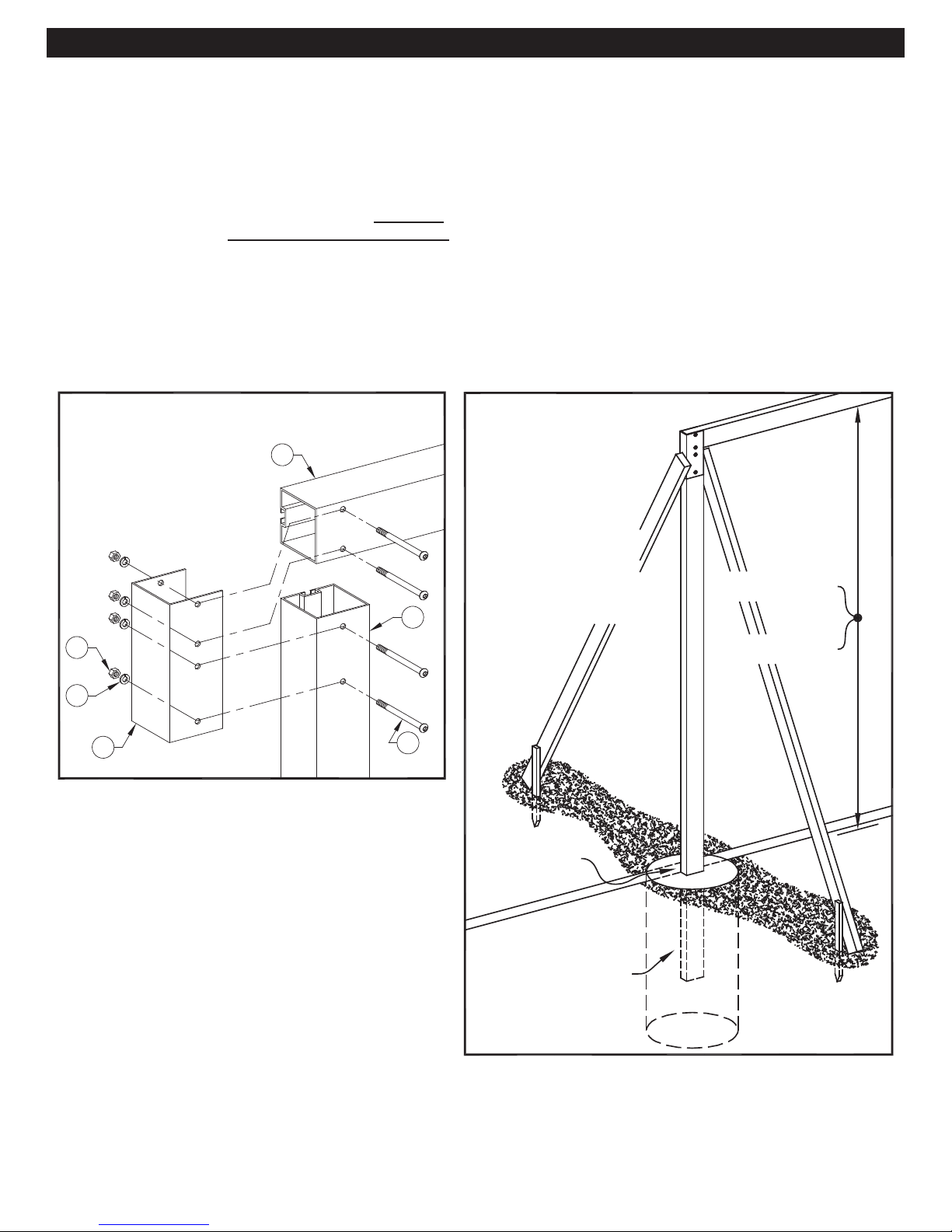
1.
Soccer goals will be pre- ass embled o n the gr ound, befor e being inst alled in the c oncr ete foot ings. See Detail "A" f or
assembly details.
If soccer goals are being u sed with outdoor ground sleeves, f ollow the installation instruc tions provided with the ground
sleeves (posts require gr ound sleeve anchor pins to be locat ed in the 24" position). If soccer goals are bein g installed
permanently into concrete footings, proceed to Step No. 2.
2.
Locate and dig footings f or sideframes. CAUT ION – Contact your local utility com panies to locate buried e lectrical,
gas and water lines before digging holes for footings. Also, check for overhead utilities. See Detail “C”.
3.
Raise the assembled soccer goal into position, with the bottom end of the posts suspended in the holes for the
footings. Support t he goal assem bly at the proper location and height, with 2x4 ’s, etc. The bottom of the crossbar
must be located at th e exac t dim ension ab ove th e playin g surf ace, with the f ace of the goal e ven with t he o uter edge
of the court line. See Details “B” and "C".
4.
After double-checking the position of the soccer goal, pour the concrete footings.
Detail "A"
UPPER CORNER
ASSEMBLY
1
Stationary
Goals
6
5
3
5.
Allow the concrete footings to cure for a minimum of
three days before assembling soccer net to goal
with net hooks. Net hooks are installed into the
continuous slot on the backside of the soccer goal
by inserting and turning c lockwise. See Deta il “G”.
Net is installed by weaving perimeter hem thru
opening in net hook.
Detail "B"
Suspend pre-assembled
soccer goal in holes for
footings, by clamping 2x4's,
etc. to sideframes as shown.
The bottom of the crossbar
must be located at the exact
dimension above the playing
surface as shown at right, with
the face of the goal even with
the outer edge of the courtline
2
4
(See also Detail "C").
SEE DETAIL "C"
at No. 475100, 465100
at No. 448100, 442100
8'-0"
6'-6"
6.
Soccer goal is now ready for use.
BOTTOM END OF
POST IS SUSPENDED
IN HOLE FOR
CONCRETE FOOTING
3
Page 4
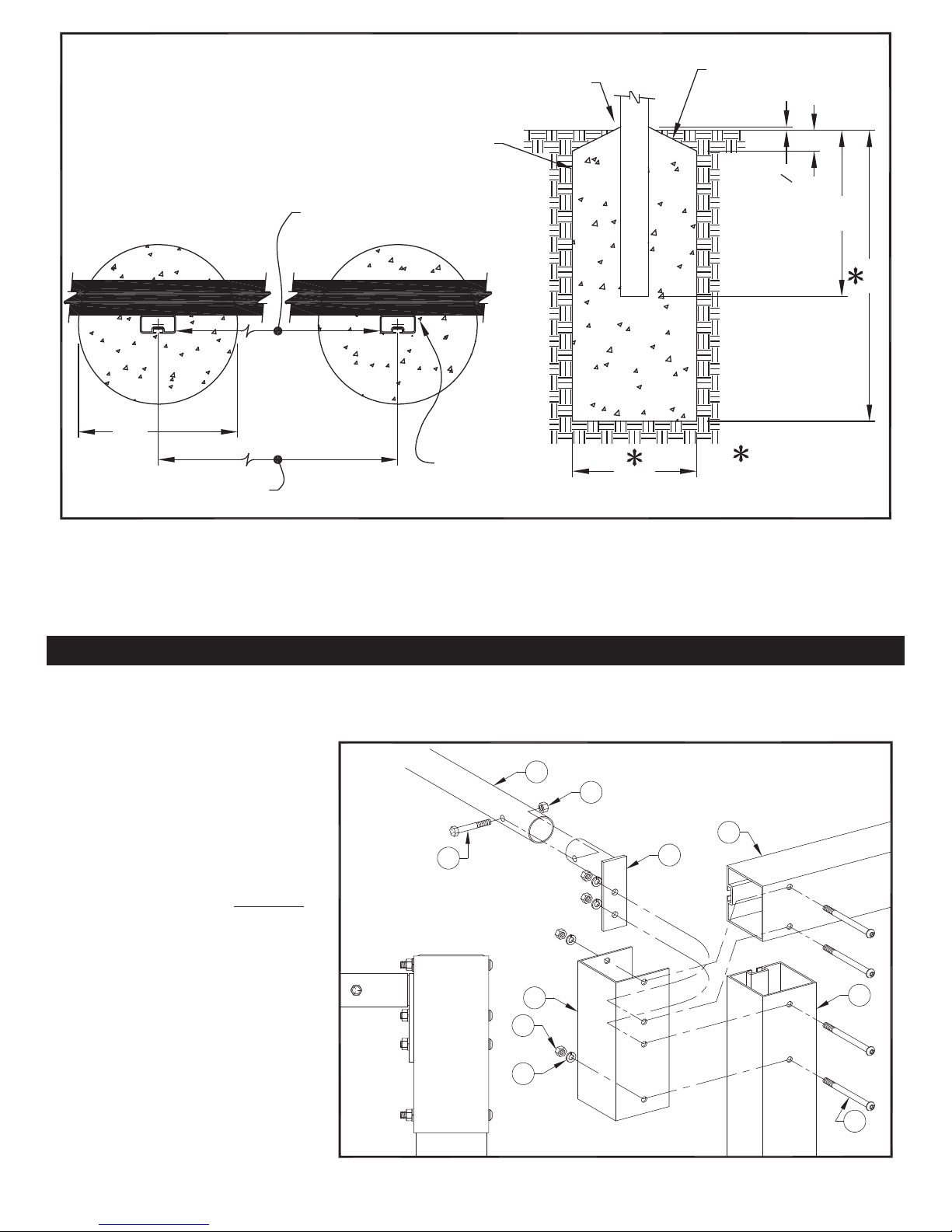
Detail "C"
CAUTION - Contact local utility
companies to locate buried electrical,
gas, water lines, etc. BEFORE
DIGGING HOLES FOR FOOTINGS.
Also check for overhead utiltiies.
FOR PROPER DRAINAGE
CONCRETE FOOTING
24'-0" - No. 475100, 465100
18'-0" - No. 448100
12'-0" - No. 442100
TOP OF FOOTING AT
POLE MUST BE AT
LEAST 1/2" ABOVE
PLAYING SURFACE
SLOPE TOP OF CONCRETE
FOOTING APPROXIMATELY
3" BELOW GRADE FOR
PROPER DRAINAGE
3"
"
2
1
2'-0"
3'-6"
1'-6"
24'-4" - No. 475100, 465100
18'-4" - No. 448100
12'-4" - No. 442100
FRONT FACE OF
POSTS ALIGNS
WITH OUTER
EDGE OF COURT
LINE
1'-6" Ø
FOOTING DETAIL
Minimum recommended
footing size shown.
Increase size of footings
as required according to
local soil conditions.
PORTABLE SOCCER GOALS
1.
Locate crossbar and posts face-down on playing surface near where the goal will be used for play, for ease of
assembly. The goal will be raised to its playing position after assembly is complete.
2.
Assemble crossbar to each post
as shown in Detail "D".
3.
Assemble formed backstays to
posts as shown in Details "D" and
"E".
4.
Assembly of portable socc er goal
is now complete. CAUTION –
This step requires four adults
who are capable of lifting this
soccer goal. The assembled
portable soccer goal can now be
raised to its pla ying position, and
moved into place. Proceed
immediately to Step 5 for
installation of anchor system.
Detail "D"
Portable
Goals
11
9
12
3
6
& BACKSTAY
ASSEMBLY
1
10
UPPER CORNER
2
5
4
4
Page 5
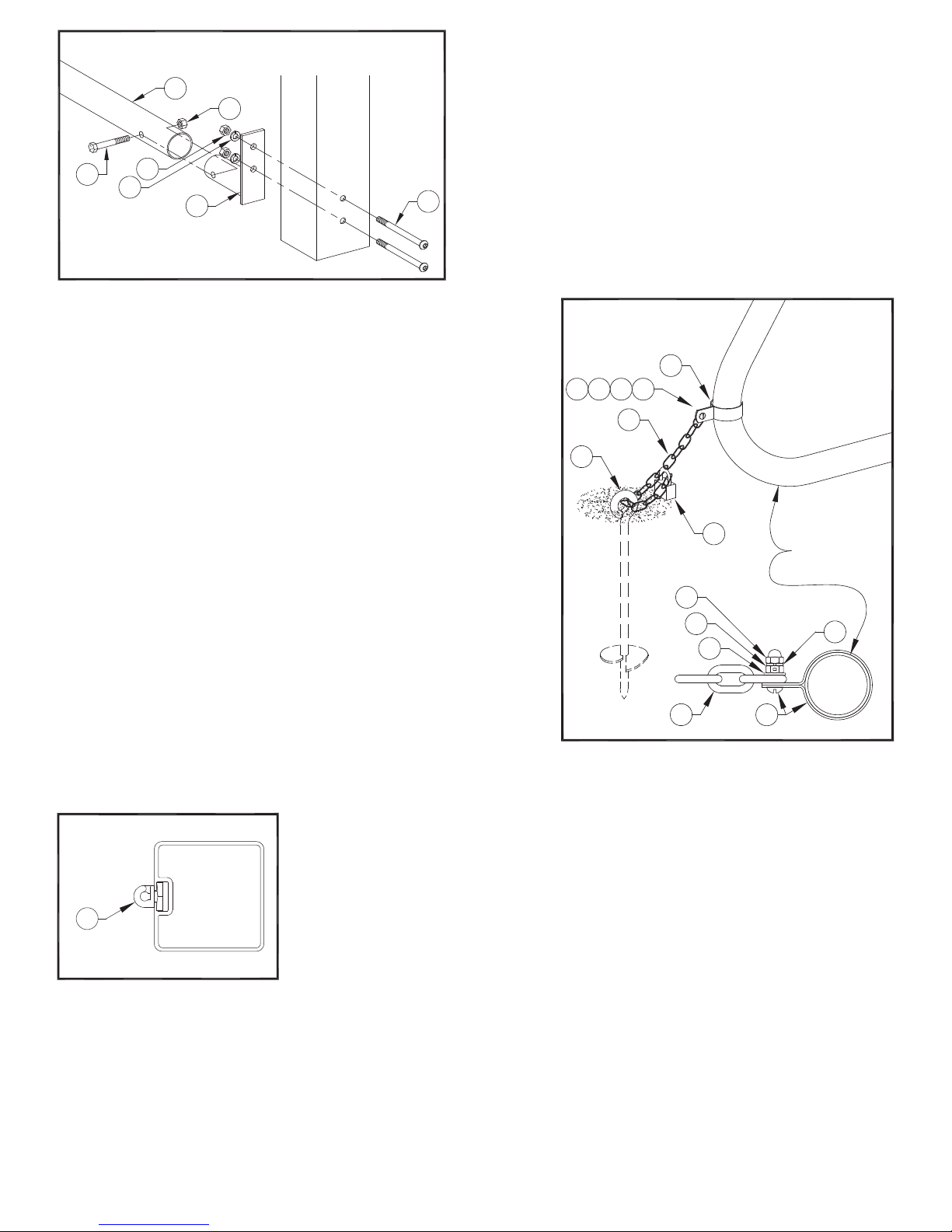
Detail "E"
BACKSTAY ASSEMBLY
LOWER END
9
12
11
6
5
10
4
Portable
Goals
5.
The anchor system must be installed on the backstay on each
sideframe. See Detail “F” for assembly details. Begin by locating
each portable soccer goal in its final position on the playing field.
6.
Within 6" of the bac k end of the backstay, install the auger-type
ground anchor into the ground. An extra piece of steel bar ( not
provided) will assist in screwing the anch or into the ground . The
anchor must be installed s o that the top of the eye is alm ost flush
with the playing surface. See Detail “F”.
7.
Route the loose end of the c hain through the eye on the anch or.
Pull the chain fairly tight, and attach it to itself with the padlock
provided. See Detail “F”.
8.
Repeat for all four backstays.
9.
Net hooks are installed into the contin uous slot o n the bac ks ide of
the soccer goal by inserting and turning clockwise. See Detail
“G”. Net is installed by weaving perim eter hem thru opening in
net hook.
Detail "F"
1516
17
18
19
14
13
17
15
14
20
FORMED
BACKSTAY
16
10.
Portable soccer goals are now ready for use.
Detail "G"
7
18
13
5
Page 6
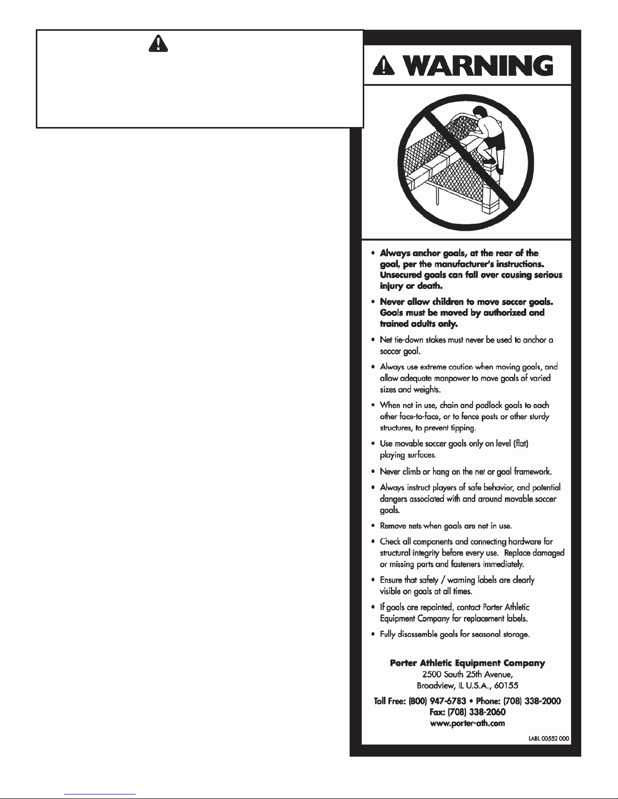
WARNING
ALL PORTABLE SOCCER GOALS MUST BE ANCHORED, TO COMPLY WIT H THE
“GUIDELINES FOR MOVABLE SOCCER GOAL SAFE TY ” AS PUBLISHED BY THE
TO OBTAIN COPIES OF THIS DOCUMENT, CONTACT PORTER, OR WRITE TO THE U.S.
Contact Porter for additional copies of this document, and for
additional warning lab els .
U.S. CONSUMER PRODUCT SAFETY COMMISSION.
CONSUMER PRODUCT SAFETY COMMISSION AT THIS ADDRESS:
U.S. CONSUMER PRODUCT SAFETY COMMISSION
WASHINGTON, D.C. 20207
6
Page 7
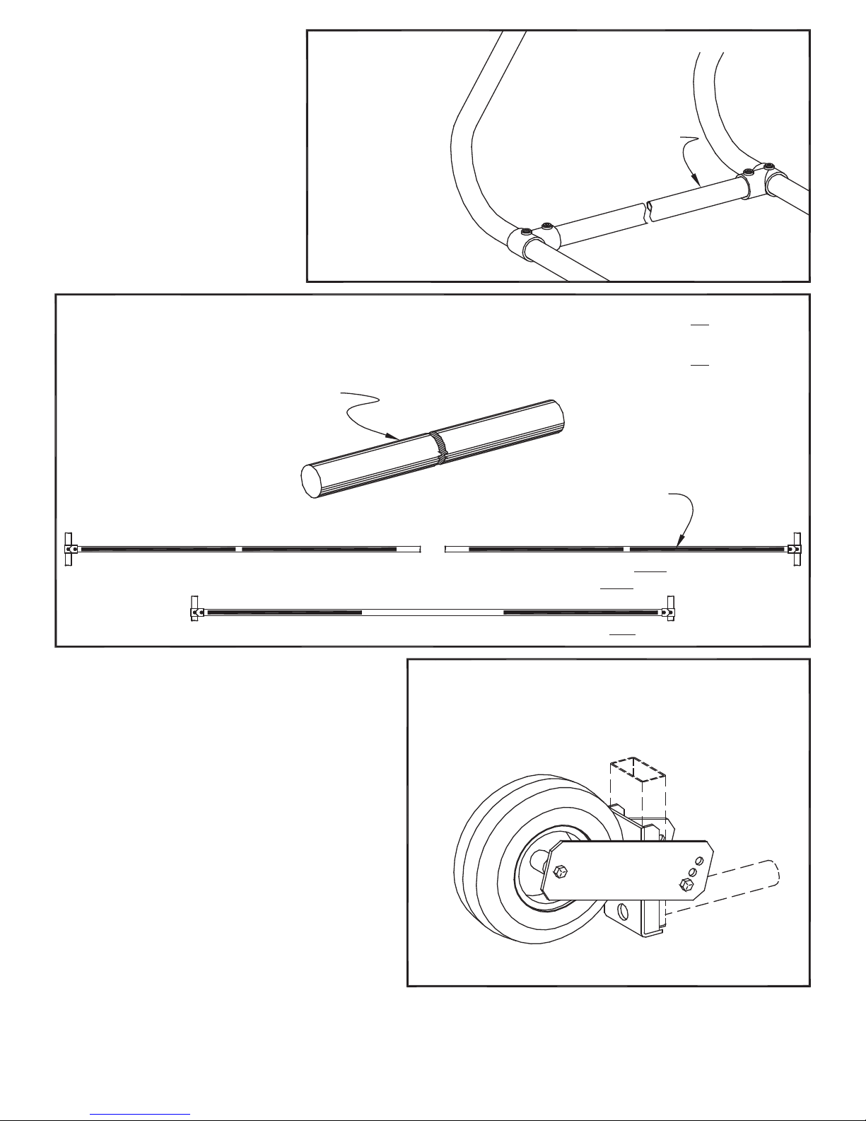
If portable soccer goals are to be
transported frequently, it is highly
recommended that the optional No.
412 Rear Spreader Tube Kit be
installed, and the optional No.
00293000 Transport Kit be used.
Also, for added stability the optional
No. 00413040 Internal W eight Bar Kit
should be installed inside the Rear
Spreader Tube.
No. 477100 & 467100 Soccer Goals
require No. 41224G Kit
No. 446100 Soccer Goal
requires No. 41218G Kit
No. 440100 Soccer Goal
requires No. 41212G Kit
REAR SPREADER KITS
(OPTIONAL)
Spreader tube clamps between
backstays on sideframes of
portable goal, stabilizing unit
while transporting
INTERNAL WEIGHT BAR KIT
Each bar weighs approximately 17 pounds
(total 68 pounds per set of four)
No. 477100 or 467100 24'-0" wide Soccer Goal requires one set of four for Each goal
No. 446100 18'-0" wide Soccer Goal requires one set of four for Each goal
No. 440100 12'-0" wide Soccer Goal requires one set of four for each Pair of goals
No. 00413040
SET OF FOUR
(OPTIONAL)
SOCCER GOAL TRANSPORTER
Pair of No. 477100 or 467100 Soccer Goals
requires
Pair of No. 446100 Soccer Goals
requires two No. 00413040 Kits
Pair of No. 440100 Soccer Goals
requires one No. 00413040 Kit
Weight bars are inserted
inside the rear spreader
kit (see above)
No. 00293000
SET OF TWO
(OPTIONAL)
two No. 00413040 Kits
7
Page 8
GUARANTEE
All materials and workmanship of basic materials are guaranteed to be free and clear of defects.
Defective material will be repaired or replaced, at our option, subsequent to complete information
being received by us concerning the nature of the defect, for a period of one year from the date of
completion of the assembly/installation.
NAME OF DEALER: NAME OF INSTALLATION COMPANY
PHONE #: PHONE #:
Porter Order Number:
Date of Completion:
Care has been taken to fabricate and install this equipment to provide years of safe, satisfactory use
and trouble-free service. The key to satisfactory service from this equipment is proper operation and
care. Should any malfunctions occur, please notify your supervisor and call your local Porter Dealer
or Representative.
WARNING: This product can expose you to Titanium Dioxide,
which is known to the State of California to cause cancer.
For more information go to www.p65warnings.ca.gov.
Toll Free: (888) 277-7778 x Phone: (708) 338-2000 x Fax: (708) 338-2060
SAVE THESE INSTRUCTIONS FOR FUTURE USE
THIS WARNING IS GIVEN IN COMPLIA NCE
WITH CALIFORNIA’S PROPOSITION 65:
WARNING
This product contains chemicals known to the
State of California to cause cancer, birth defects
or other reproductive harm.
Porter Athletic, Inc.
2500 South 25
th
Avenue, Broadview, IL U.S.A., 60155
www.porterathletic.com
8
E
 Loading...