

Portawattz 1750 Owner's Manual


Table of Contents
1. Introduction....................................................................................................2
2. How Your Portawattz 1750 Works...............................................................2
2.1 Principle of Operation........................................................................................3
2.2 Portawattz 1750 Output Waveform....................................................................3
3. Quick Checkout..............................................................................................4
3.1 Power Source ..................................................................................................... 5
Battery.........................................................................................................5
DC Power Supply........................................................................................5
3.2 Cables................................................................................................................. 5
3.3 Test Loads.......................................................................................................... 6
3.4 Connections........................................................................................................7
4. Installation ......................................................................................................9
4.1 Where to Install..................................................................................................9
4.2 Battery..............................................................................................................10
Battery Type .............................................................................................. 10
Battery Sizing............................................................................................ 11
Using Multiple Batteries............................................................................14
Battery Tips............................................................................................... 15
Alternators and Charging Systems.............................................................16
4.3 Cables............................................................................................................... 17
4.4 Connections......................................................................................................18
AC Connections.........................................................................................18
Ground Wiring...........................................................................................20
DC Wiring................................................................................................. 21
5. Operation ......................................................................................................23
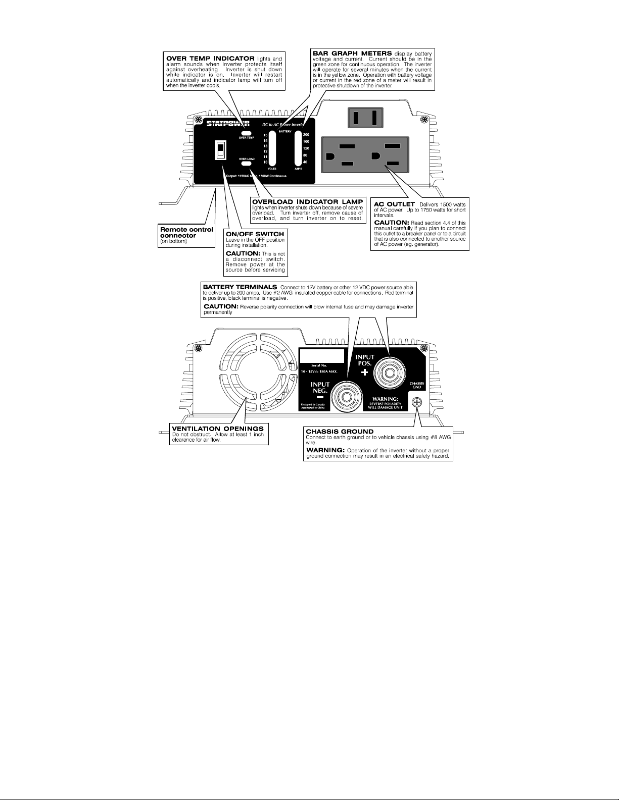
5.1 Controls and Indicators.................................................................................... 23
5.2 Operating Limits...............................................................................................24
Power Output............................................................................................. 24
Input Voltage.............................................................................................25
6. Troubleshooting............................................................................................26
6.1 Common Problems........................................................................................... 26
Buzz in Audio Systems.............................................................................. 26
Television Interference..............................................................................26
6.2 Troubleshooting Guide.....................................................................................27
7. Maintenance..................................................................................................28
8. Limited Warranty ........................................................................................29
9. Product Specifications..................................................................................31
9.1 Electrical Performance ..................................................................................... 31
9.2 Dimensions.......................................................................................................31
10. Other Products From Statpower Technologies........................................32
Portawattz is a trademark of Statpower Technologies Corporation. Copyright 1996, 1997, 1999 Statpower
Technologies Corp oration. All r ights rese rved.
1

1. Introduction
Your new Portawattz 1750 inverter is a member of the most advanced line of
DC to AC inverters available today. It will give you years of dependable
service in your boat, RV, service vehicle or remote home.
To get the most out of your Portawattz 1750, it must be installed and used
properly. Please read the installation and operating instructions in this
manual carefully before installing and using your Portawattz 1750. Pay
special attention to the CAUTION and WARNING statements in this
manual and on the Portawattz 1000. CAUTION statements identify
conditions or practices which could result in damage to your Portawattz 1750
or to other equipment. WARNING statements identify conditions or
practices that could result in personal injury or loss of life.
2. How Your Portawattz 1750 Works
An inverter is an electronic device that converts low voltage DC (direct
current) electricity from a battery or other power source to standard 115 volt
AC (alternating current) household power. In designing the Portawattz 1750,
Statpower has used power conversion technology previously employed in
computer power supplies to give you an inverter that is smaller, lighter, and
easier to use than inverters based on older technology.
Figure 1. Principle of Operation
2

2.1 Principle of Operation
The Portawattz 1750 converts power in two stages. The first stage is a DCto-DC converter which raises the low voltage DC at the inverter input to 145
volts DC. The second stage is the actual inverter stage. It converts the high
voltage DC into 115 volts, 60 Hz AC.
The DC-to-DC converter stage uses modern high frequency power
conversion techniques that eliminate the bulky transformers found in
inverters based on older technology. The inverter stage uses advanced power
MOSFET transistors in a full bridge configuration. This gives you excellent
overload capability and the ability to operate tough reactive loads like lamp
ballasts and induction motors.
2.2 Portawattz 1750 Output Waveform
The AC output waveform of the Portawattz 1750 is called a "quasi-sine
wave" or a "modified sine wave". It is a stepped waveform that is designed
to have characteristics similar to the sine wave shape of utility power. A
waveform of this type is suitable for most AC loads, including linear and
switching power supplies used in electronic equipment, transformers, and
motors. This waveform is much superior to the square wave produced by
some other DC to AC inverters.
CAUTION: RECHARGEABLE APPLIANCES
Certain rechargers for small nickel cadmium batteries can be damaged
if connected to the Portawattz. Two particular types of equipment are
prone to this problem:
1) small battery operated appliances such as flashlights, razors,
and night lights that can be plugged directly into an ac
receptacle to recharge.
2) certain battery chargers for battery packs used in hand power
tools. These chargers have a WARNING label stating that
dangerous voltages are present at the battery terminals.
Do NOT use the Portawattz with the above equipment.
3

Figure 2. Mod ified Sine Wave
This problem does not occur with the vast majority of battery operated
equipment. Most of this equipment uses a separate charger or transformer
that is plugged into the AC receptacle and produces a low voltage output. If
the label on the AC adapter or charger states that the adapter or charger
produces a low voltage AC or DC output (less than 30 volts), the Portawattz
will have no trouble powering this charger or adapter safely.
The modified sine wave produced by the Portawattz 1750 is designed to have
an RMS (root mean square) voltage of 115 volts, the same as standard
household power. Most AC voltmeters (both digital and analog) are
sensitive to the average value of the waveform rather than the RMS value.
They are calibrated for RMS voltage under the assumption that the waveform
measured will be a pure sine wave. These meters will not read the RMS
voltage of a modified sine wave correctly. They will read about 2 to 20 volts
low when measuring the output of the Portawattz 1750. For accurate
measurement of the output voltage of the Portawattz 1750, a true RMS
reading voltmeter, such as a Fluke 87, Fluke 27, Tektronix DMM249, or
B&K Precision Model 391, must be used.
3. Quick Checkout
This section will give you the information you need to quickly hook-up your
Portawattz 1750 and check its performance before going ahead with
permanent installation. You will need the following:
a) a 12 volt DC power source
b) two cables to connect the power source to the Portawattz 1750
c) a test load that can b e plugged into the AC receptacle on the
Portawattz 1750.
4

3.1 Power Source
For optimum performance, the power source must provide between 11 and
15 volts DC and must be able to supply sufficient current to operate the test
load. As a rough guideline, divide the wattage of the test load by 10 to
obtain the current (in amperes) the power source must deliver.
Example:
Test load is rated at 250 watts.
Power source must be able to deliver
250 ÷ 10 = 25 amperes.
Battery
Use a fully-charged 12 volt (nominal) battery that can deliver the required
current while maintaining its voltage above 11 volts. A fully-charged (12
volt) automobile battery is capable of delivering up to 50 amperes without an
excessive voltage drop.
DC Power Supply
Use a well regulated DC power supply that has an output voltage between 11
volts and 14 volts and can deliver the required current. If the supply is
adjustable, make sure that the output voltage is adjusted to be between 11
volts and 14 volts. The inverter may shut down if the voltage is outside these
limits and may be damaged if the voltage is above 16 volts. Also ensure that
any current limit control is set so that the power supply can deliver the
required current.
3.2 Cables
Your cables must be as short as possible and large enough to handle the
required current. This is to minimize the voltage drop between the power
source and the inverter when the inverter is drawing current from the power
source. If the cables introduce an excessive voltage drop, the inverter may
shut down when drawing higher currents because the voltage at the inverter
drops below 10 volts.
5

We recommend #2 AWG stranded
copper cable that is no longer than 4
ft (1.5 m) if you want to test the
Portawattz 1750 to its maximum
ratings. For short term testing at
reduced power levels, the guidelines
below should be followed.
Power
Consumed
(Watts)
100 16
250 12
500 8
Table 1 - Test Load Power
Consumption For Short Term Test
Min. Copper
Cable Size
(AWG)
Ideally, the cable should be no more
than 4 ft (1.5 m) long.
Attach 5/16 inch ring terminals to the ends of the cables to be attached to the
DC terminal studs on the Portawattz 1750. The ring terminals must be
crimped with a proper crimping tool. Another option is to use Ilsco or
equivalent box-lug terminals (available at electrical parts suppliers) sized for
the wire gauge of the cable and for a 5/16 inch stud. The bare cable end is
inserted into the lug terminal and secured with a set-screw.
The other end of the cable, which is connected to the power source, must be
terminated with a lug or other connector that allows a secure, low resistance
connection to be made to the power source. For instance, if the power source
is a battery, the cable must be terminated with a battery terminal that clamps
to the post on the battery.
A SOLID, LOW RESISTANCE CONNECTION TO THE POWER SOURCE
IS ESSENTIAL FOR PROPER OPERATION OF THE PORTAWATTZ 1750.
3.3 Test Loads
Use only equipment rated for 110-120 volt, 60 Hz AC operation that has a
power consumption of 1500 watts or less. We recommend that you start with
a relatively low power load, such as a 100 watt lamp, to verify your test setup before trying high power loads.
6

Figure 3. Connections to the Portawattz
3.4 Connections
Follow the connection sequence described below.
STEP 1 Ensure that the ON/OFF switch on the Portawattz 1750 is in the
OFF position. If the power source is a DC power supply, switch it
off as well.
STEP 2 Connect the cables to the power input terminals on the rear panel of
the Portawattz 1750. The red terminal is positive (+) and the black
terminal is negative (-). Place the cable connector (ring terminal or
box lug) on the stud and then install the supplied lock washer and
nut. Tighten the nut with a wrench to a torque of 9 – 10 ft-lbs (12 –
13 Nm).
STEP 3 Connect the cable from the negative (black) terminal of the
Portawattz 1750 to the negative terminal of the power source. Make
a secure connection.
CAUTION! LOOSELY TIGHTENED CONNECTORS RESULT IN
EXCESSIVE VOLTAGE DROP AND MAY CAUSE OVERHEATED WIRES
AND MELTED INSULATION.
STEP 4 Before proceeding further, carefully check that the cable you have
just connected connects the negative terminal of the Portawattz
1750 to the negative output terminal of the power source. Power
connections to the Portawattz 1750 must be positive to positive and
negative to nega t ive.
CAUTION! REVERSE POLARITY CONNECTION (POSITIVE TO
NEGATIVE) WILL BLOW THE FUSES IN THE PORTAWATTZ 1750 AND
MAY PERMANENTLY DAMAGE THE PORTAWATTZ 1750. DAMAGE
CAUSED BY REVERSE POLARITY CONNECTION IS NOT COVERED BY
YOUR WARRANTY.
7

STEP 5 Connect the cable from the positive (red) terminal of the Portawattz
1750 to the positive terminal of the power source. Make a secure
connection.
WARNING! You may observe a spark when you make this connection
since current may flow to charge capacitors in the Portawattz 1750.
MAKE THIS CONNECTION IN THE PRESENCE OF FLAMMABLE
FUMES. EXPLOSION OR FIRE MAY RESULT.
DO NOT
STEP 6 If you are using a DC power supply as the power source, switch it
on. Set the ON/OFF switch on the Portawattz 1750 to the ON
position. Check the meters and indicators on the front panel of the
Portawattz 1750. The voltage bar graph should indicate 11 to 14
volts, depending on the voltage of the power source. If it does not,
check your power source and the connections to the Portawattz
1750. The other indicators should be off.
STEP 7 Set the Portawattz 1750 ON/OFF switch to the OFF position. The
indicator lights may blink and the internal alarm may sound
momentarily. This is normal. Plug the test load into the AC
receptacle on the front panel of the Portawattz 1750. Leave the test
load switched off.
STEP 8 Set the Portawattz 1750 ON/OFF switch to the ON position and turn
the test load on. The Portawattz 1750 should supply power to the
load. If it does not, refer to the troubleshooting section of this
manual. If you plan to measure the output voltage of the Portawattz
1750, refer to Section 2.2 of this manual.
8
 Loading...