

Specifications
Channels 15 GMRS
RF Output Power 1 Watt Max.
Audio Output Power 500mw
Frequency Stability +5PPM
Operating Voltage 6.0V
Dimensions (L x W x D) 3.5 x 2x 1 in.
Weight (with battery) 7 oz
Porta Phone Co.
145 Dean Knauss Drive
Narragansett, RI 02881
800-233-1113
In RI: 401-789-8700
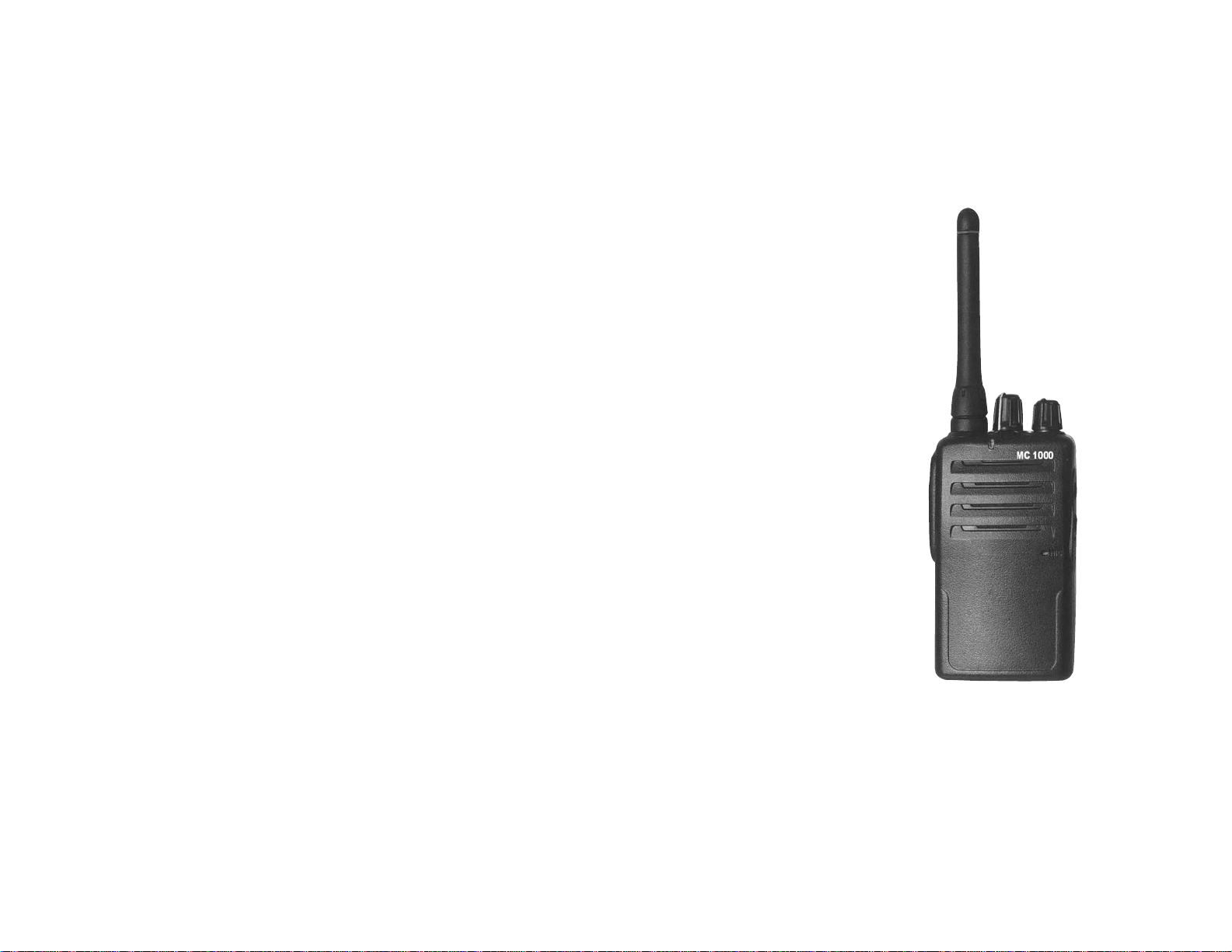
Competitor
MC 1000
Professional Wireless
Communicator
Features
15 Channels
38 Group Mode Tones
VOX Function
Call Tone
1 Watt Power Output
Low Battery Alarm
Ni-MH Battery Pack
Desktop charger
Range up to 2 Miles
User’s Manual
Marketing Statement
The Competitor MC - 1000 is a professional two-way transceiver . The radio has been
tested and complies with FCC limits with regard to exposure to RF and electromagnetic
energy for use by individuals aware of the hazards during the course of em ployment.
FCC License Information
IMPORTANT NOTICE: FCC LICENSE REQUIRED
All professional transceivers that operate in the GMRS band require (Federal
Communications Commission) FCC licensing.
A user must be licensed prior to operating on Channels 1 through 7 on high power or 15
through 22, which comprise the GMRS channels of this radio. Serious penalties could
result for unlicensed use of GMRS channels, in violation of FCC rules. Opera tion of this
radio is subject to additional rules specified in 47 C.F.R. Part 95.
Licensed users will be issued a call sign by the FCC, which should be used for station
identification when operating this radio. GMRS users should also cooperate by engaging
in permissible transmissions only, avoiding channel interference with other GMRS users,
and being prudent with the length of their transmission time.
For licensing information and application forms, please call the FCC Hotline at 800-418FORM. Request form #159 and form #605. Questions regarding the license application
should be directed to the FCC at 888-CALL-FCC. Additional information is available on
the FCC's website at www.fcc.gov <http://www.fcc.gov>.
During the licensing process you may operate your Competitor MC1000 system with the
temporary permit included in this manual.
FCC ID: B4HMC1000 Canada: IC: 3064A-MC1000
FCC Warning Statement:
This device complies with part 15 of the FCC Rules. Operation is subject to the following
two conditions: 1) This device may not cause harmful interference, and 2) this device
must accept any interference received, including interfere nce that may cause undesired
operation.
1
Warnings / Basic RF
Exposure Instructions
To make sure that your exposure to RF electromagnetic energy is within the FCC
allowable limits:
* DO NOT operate the radio without an antenna attached, or an antenna other than that
supplied by the manufacturer. Doi ng so could cause you to exceed FCC RF expo sure
limits.
* DO NOT transmit for more tha n 50% of total radio use time. Transmitting more than
50% of the time may exceed FCC RF exposure compliance requirements. (This device is
authorized to operate at a duty factor not to exceed 50%. In August 1996, the Federal
Communications Commission (FCC) adopted RF exposure guidelines with safety levels
for handheld wireless devices.)
* ALWAYS keep the antenna at least 2.5 cm (1 inch) away from the body when
transmitting to ensure FCC RF exposure compliance requirements are not exceeded. To
provide the best sound quality, hold the antenna at least 5 cm (2 inches) from your mouth,
and slightly off to one side.
* ALWAYS maintain a 2.5 cm separation distance from the antenna to a person(s). You,
as the qualified end-user of this radio device must control the exposure conditions of
bystanders to ensure the minimum 2.5 cm separation distance is maintained between the
antenna and nearby persons for satisfying RF Exposure compliance. The operation of this
transmitter must satisfy the requirements of Occupational/Controlled Exposure
Environment, for work-related use. Transmit only when person(s) are at least 2.5 cm
distance from the properly installed, externally mounted antenna.
Changes or modifications not expressly approved by the party responsible for compliance
could void the user's authority to operate the equipment. All repairs or maintenance to
the transmitter must be performed by, or under the supervision of, a certified lan d m obile
radio technician. Any adjustments to the transceiver that could result in changes of radio
performance is a violation of FCC rules and is strictly prohibited.
It is unlawful to replace or substitute any component ie. crystal, semiconductor, etc., or to
modify the circuit board of this RF device in any manner. Any component change or
modification to the internal circ uitry is forbidden and is a violation of the FCC rules.
Failure to comply with these guidelines could cause the user to loose the authority to
operate this equipment.
2

System Set-Up
FCC Label Confirmation
Confirm that the FCC ID label is affixed to the inside of the battery compartment before
installing the battery and using the Competitor MC-1000.
Antenna Installation
Firmly attach the antenna to the radio by turning it clockwise until it tightens.
Belt Clip Assembly
Install the military belt clip w ith the hardware included. Two Phillips head screws are
provided.
Battery Installation
Your MC - 1000 radio has been shipped with the battery separate from the actual
transceiver portion.
To install the battery slide it onto the back of the transceiver until the latch at the bottom
clicks and holds it in place. Once the battery is installed follow the charging procedure
before operation (See page 5).
Operating Instructions
Refer to figure 1 for an explanation of controls, adj ustments and switches.
1. The Power switch / Volume Control Knob (item 2) turns the transceiver ON and Off
and also sets the sound level of incoming signals. Turn the power switch / volume control
clockwise to turn the transceiver "on".
2. Set the operating channel via the Channel Selector knob (item 1). Rotate the Channel
Knob setting it to your desired channel. Channel numbers and are printed on the radio. In
addition the radio features an audible channel announcement and will tell the user the
channel selected.
3. Before making a call, monitor the channel to make sure that no-one is using the
frequency. To monitor the channel depress and hold the monitor button (item 9).
4. To make a call press and hold the PTT Key (item 7 ) on the side of the radi o and speak
into the microphone The LED indicator (item 3) will turn red confirming transmission.
5. For best voice translation speak directly into the microphone (item 6) using normal
voice levels. Release the PTT key when you are finished speaking.
3
6. Incoming messages are received through the built in Speaker (item 5). Adjust the
speaker sound level by rotating the volume control knob as follows: clockwise - higher,
counter clockwise - lower. Incoming messages are confirmed by green light on LED
Indicator.
7. The Accessory Jack (item 4) allows addition of audio equipment such a speakermicrophone or headsets. Use only those accessories that are specifically designed for use
with this transceiver.
8. The MC-1000 features a Call function that allows users in a group to alert select
members of incoming messages. To set the radio to Call Mode press and hold down the
Call Key (item 8) while turning th e radio "on".
Adjust the channel selector choosing a desired call tone, up to 15 different sounds are
available. Press the PTT Key to store this call tone and turn the radio off to set it in the
Call Mode.
When you want to announce an eminent transmission to a selected partner press the Call
Key before using the PTT Key and actually transmitting. Your partner will be alerted to
the incoming message just before it arrives.
Note: When battery voltage
becomes low, the LED
Indicator on radio will turn
solid red color and radio
transmissions will stop.
4
Figure 1

CHARGING THE BATTERY PACK
1. After purchase or after extended storage (greater than 2 months) charge an d discharge
the battery two or three times. After these cycles the battery will return to its normal
operating capacity.
2. Plug the AC adapter cable into the jack located on the rear of desktop charger ba se.
3. Slide the transceiver & battery pack into the charger.
4. Plug adapter into AC outlet.
5. Make sure the battery pack contacts are touching the charging terminals. The charger
base LED turns red indicating battery is charging.
6. The charger base LED light will flash when the battery is fully charged in 2.5 to 3
hours.
7. Remove the transceiver from charging base when charging is completed.
CAUTIONS
1. Only use the supplied battery to operate this transceiver.
2. Do not short the battery terminals or dispose of the battery by fire.
3. Operating the transceiver while charging the battery pack will interfere with charging
process.
4. Do not recharge a fully charged battery pack.
5. Do not charge if the battery is wet. Dry with cloth before charging to avoid damage.
6. All batteries can cause property damage and/or bodily injury such as burns if a
conductive material touches exposed terminals.
Note: When battery voltage becomes low, the LED Indicator on radio will turn solid red
color and radio transmissions will stop.
5
VOICE ACTIVATED CONTROL (VOX)
Vox operation allows hands-free transmission when using a headset. This mode allows
the user to initiate transmissions with the energy in their voice instead of pressing a push
to talk button.
1. To Begin VOX
Press and hold CALL & PTT keys while turning power on. A double beep will sound
indicating that VOX mode is active. Release keys.
2. Set Microphone Sensitivity
Adjust desired VOX sensitivity by turning channel selector (1-16) while listening to
beeps.
The lower the number the less sensitive the microphone.
The higher the number the more sensitive the microphone.
For example:
1=Low sensitivity, 8=Mid sensitivity, 16=High sensitivity
Press PTT key again, and microphone sensitivity number will be announce d and locked
in.
3. Select Channel / Frequency
Channel Selector can now be used for Channel/Frequency Selection.
4. Attach Headset
Plug in an optional headset into audio jacks, and begin speaking in VOX.
Important: Place microphone 1/4” directly in front of mouth. Speak DIRECTLY into
microphone.
5. To End VOX
Press PTT key to Cancel VOX transmission.
Note: If the VOX Gain levels are set to a higher sensitivity, lower ambient noise may
accidentally activate the microphone.
6

Frequency List
Channel # Receive/Transmit Frequency
1 462.5625 MHz
2 462.5875 MHz
3 462.6125 MHz
4 462.6375 MHz
5 462.6625 MHz
6 462.6875 MHz
7 462.7125 MHz
15 462.550 MHz
16 462.575 MHz
17 462.600 MHz
18 462.625 MHz
19 462.650 MHz
20* 462.675 MHz
21 462.700 MHz
22 462.725 MHz
• Emergency Channel: emergency use only
7
Frequency Guard
Tone squelch that eliminates the receipt of unwanted signals in your area.
FQ Guard FQ Guard FQ Guard
OFF 110.9 Hz 186.2 Hz
67.0 Hz 114.8 Hz 192.8 Hz
71.9 Hz 118.8 Hz 203.5 Hz
74.4 Hz 123.0 Hz 210.7 Hz
77.0 Hz 127.3 Hz 218.1 Hz
79.7 Hz 131.8 Hz 225.7 Hz
82.5 Hz 136.5 Hz 233.6 Hz
85.4 Hz 141.3 Hz 241.8 Hz
88.5 Hz 146.2 Hz 250.3 Hz
91.5 Hz 151.4 Hz
94.8 Hz 156.7 Hz
97.4 Hz 162.2 Hz
100.0 Hz 167.9 Hz
103.5 Hz 173.8 Hz
107.2 Hz 179.9 Hz
8

 Loading...