

Page 1
PORTA
PORTA----NAI LS, I NC
PORTAPORTA
NAILS, INC....
NAILS, INCNAILS, INC
!!!!
!!!!
PO BOX
PO BO X 1257
PO BOXPO BOX
1257
1257 1257
HOM E PAGE:
HOME PAGE: www.p o r ta
HOM E PAGE: HOM E PAGE:
WILMINGTON, NC 28402
WILMINGTON, NC 28402
WILMINGTON, NC 28402 WILMINGTON, NC 28402
www.porta----nails.com
www.portawww.porta
nails.com E
nails.comnails.com
!!!!
910
910----762
762----6334
910910
762762
E----MAIL: info@porta
MAIL: [email protected]
E E
MAIL: info@portaMAIL: info@porta
6334
63346334
!!!!
800
800----634
800800
nails.com
nails.comnails.com
634----9281
9281
634634
92819281
!!!!
FAX 910
FAX 910----763
FAX 910FAX 910
763----8650
763763
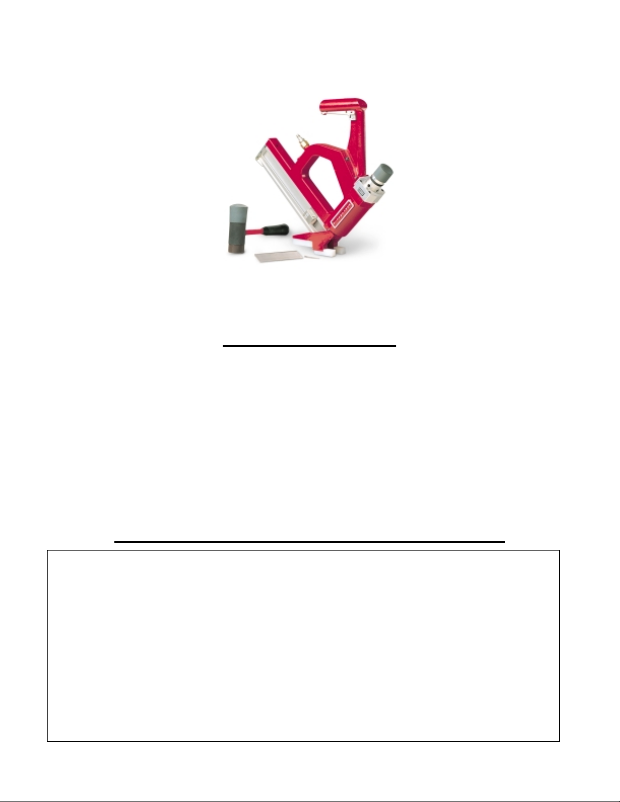
OWNER’S MANUAL
®
PORTAMATIC
Pneumatic Nailer
For Tongue and Groove Solid Wood & Hardwood Laminate
8650
86508650
Flooring, Roof Decking and Wood Sub Flooring
CAUTION - Read important safety instructions AND operation instructions BEFORE operating
your PORTAMATIC® Pneumatic Nailer.
Your new
performance throughout its lifetime. To take full advantage of these capabilities you should thoroughly
understand the proper method and technique of its operation. Therefore, we suggest you read this manual
before operating and that you save it for future reference.
PORT AMATIC
®
Pneumatic Nailer
is a quality-built machine, capable of dependable
FORM P/N 750048 (6/1/2002)
Page 2
ETL Listed:
US Patent Numbers:
Fastener Type:
Operating Pressure:
Firing Mode:
Jam Clearance:
Dimensions:
Weight:
Use only
90 P.S.I.
Hammer Actuated
Hinged Lever Type, Quick Release Gate
19” High x 20” Long x 3” Wide
Approximately 13 LBS.
PORTAMATIC
CAT. NO. 421
SPECIFICATIONS
Control Number 9801577
6,095,392 & D419,048
*
*
Porta-Nails
Porta-Nails
(See Operating Instructions Pg. 7)
Must Be Purchased Separately
®
(See Clearing a Jam Pg. 9)
PNI’s LIMITED TWO YEAR WARRANTY
PNI is proud of the products that it manufactures and warrants them to be free from
defects in materials and workmanship for 2 years. In the unlikely event that a problem
occurs, return the product to our plant freight prepaid and allowed, so that a
determination of the fault can be made. If the fault is determined to be defective
materials or workmanship, a no-charge replacement or repair will be made, at our
discretion. The product will be returned to you freight prepaid and allowed. This
warranty does not cover accidents, abuse or misuse and in no case will PNI be liable for
incidental or consequential damages. No other warranty written or verbal is authorized.
Returns for warranty service should be sent to:
Porta-Nails, Inc.
4235 US Hwy. 421 N.
Currie, NC 28435
2
Page 3

Safety Instructions
1. KNOW YOUR POWER TOOL
Read the owner's manual carefully. Learn its
applications and limitations as well as the potential
hazards specific to this tool.
2. THE OPERATOR AND ALL OTHER
PERSONNEL MUST WEAR PROPER EYE AND
EAR PROTECTION IN THE WORK AREA.
Wear safety goggles at all times. (Must comply with
ANSI Z87.1). Everyday eyeglasses have impact
resistant lenses only. They are NOT safety glasses.
Also, wear ear protectors (plugs or muffs) during
extended periods of operation
3. KEEP WORK AREA CLEAN
Cluttered areas and benches invite accidents. Floor
must not be slippery due to sawdust.
4. KEEP CHILDREN AWAY
All visitors should be kept a safe distance from work
area.
5. WEAR PROPER APPAREL
Do not wear loose clothing, gloves, neckties or
jewelry (rings, wristwatches) that could get caught in
moving parts. Wear non-slip footwear. Wear
protective hair covering to contain long hair. Roll
long sleeves above the elbow.
6. SECURE WORK
Be sure the tongue and groove of the flooring strips
are properly interlocked and secured in place before
nailing.
7. STAY ALERT
Watch what you are doing. Use common sense. Do
not operate tool when you are tired or while under the
influence of medication, alcohol or drugs.
8. ALWAYS INSPECT TOOL BEFORE
OPERATING.
Tool must be inspected prior to use to insure proper
use of power supply. Tool must be inspected to insure
proper working order. An improperly functioning tool
must not be used
9. KEEP HANDS, FEET AND OTHER BODY
PARTS AWAY FROM NAIL EJECTION AREA.
Serious injury could occur if body parts are not kept
away from nail ejection area.
10. ALWAYS ASSUME THE TOOL CONTAINS
FASTENERS.
Do not activate the tool unless the tool is placed firmly
against the work piece.
11. NO HORSEPLAY.
Do not point the tool toward yourself or anyone
whether it contains fasteners or not.
12. NEVER TRANSPORT TOOL WHILE
DEPRESSING THE TRIGGER.
13. DISCONNECT TOOL FROM AIR SUPPLY
WHEN:
Moving the tool to a new location, performing any
maintenance or repair, clearing a jam or tool is
unattended.
14. NEVER SERVICE WHILE ATTACHED TO AIR
SUPPLY.
Always disconnect the tool from the power source
when servicing, or replacing parts.
15. DO NOT USE TOOL IF OPERATING
CONTROLS ARE INOPERABLE.
Do not remove, tamper with, or otherwise cause the
tool operating controls or safety controls to become
inoperable.
16. DO NOT OPERATE TOOL IF SAFETY
FEATURES NOT WORKING PROPERLY.
Disconnect tool from power source if safety trigger or
operating controls are not working properly.
17. USE ONLY PORTA-NAIL FASTENERS.
Only use fasteners recommended by the manufacturer.
Use of other fasteners may cause serious injury,
jamming of tool or improper operation.
18. USE ONLY PRESSURE-REGULATED POWER
SOURCE.
Use only a pressure regulated power source set
at 125 psi maximum. The power source must have a
safety relief valve set at 135 psi maximum.
19. THE TOOL SHOULD NOT BE OPERATED AT
THE MAXIMUM AIR PRESSURE.
The tool air-line should be connected to the power
source through an airline pressure Regulator and an
airline Filter. The air line Regulator should never be
set higher than 110 psi as marked on the tool. Lower
pressures may be used as recommended by the
manufacturer.
20. HAZARDOUS POWER SOURCES SHALL NOT
BE USED.
Hazardous power sources including, but not limited
to, Oxygen, Combustible gases, sources whose
pressure can exceed 200 psi if the pressure Regulator
fails, bottled gases, including air should never be used.
3
Page 4
APPLI CATIONS
Your model 421
Nailing 9/16”, 25/32”, and 33/32” Hardwood Tongue and Groove Flooring. (See
Accessory Applications
PORTAMATIC
section)
®
Nailer is designed for Face Nailing and Angle
Shoe
PORTAMATIC
®
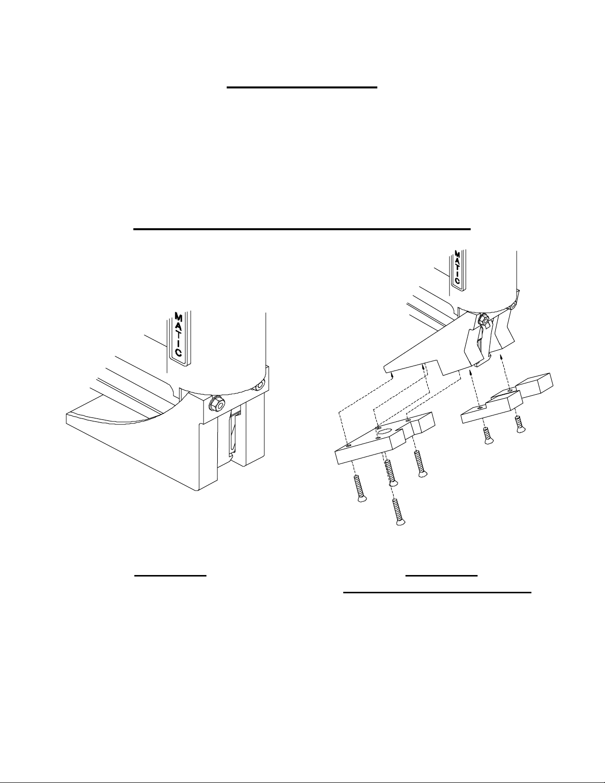
ACCESSORY SHOE APPLICATIONS
FIGURE 1
Face Nailing
Accessory Shoe Cat. No. 50113
FIGURE 2
Tongue Nailing 33/32” Flooring
Shoe P/N 50125
Shoe Base and Pads
Accessory P/N 50250
4
Page 5
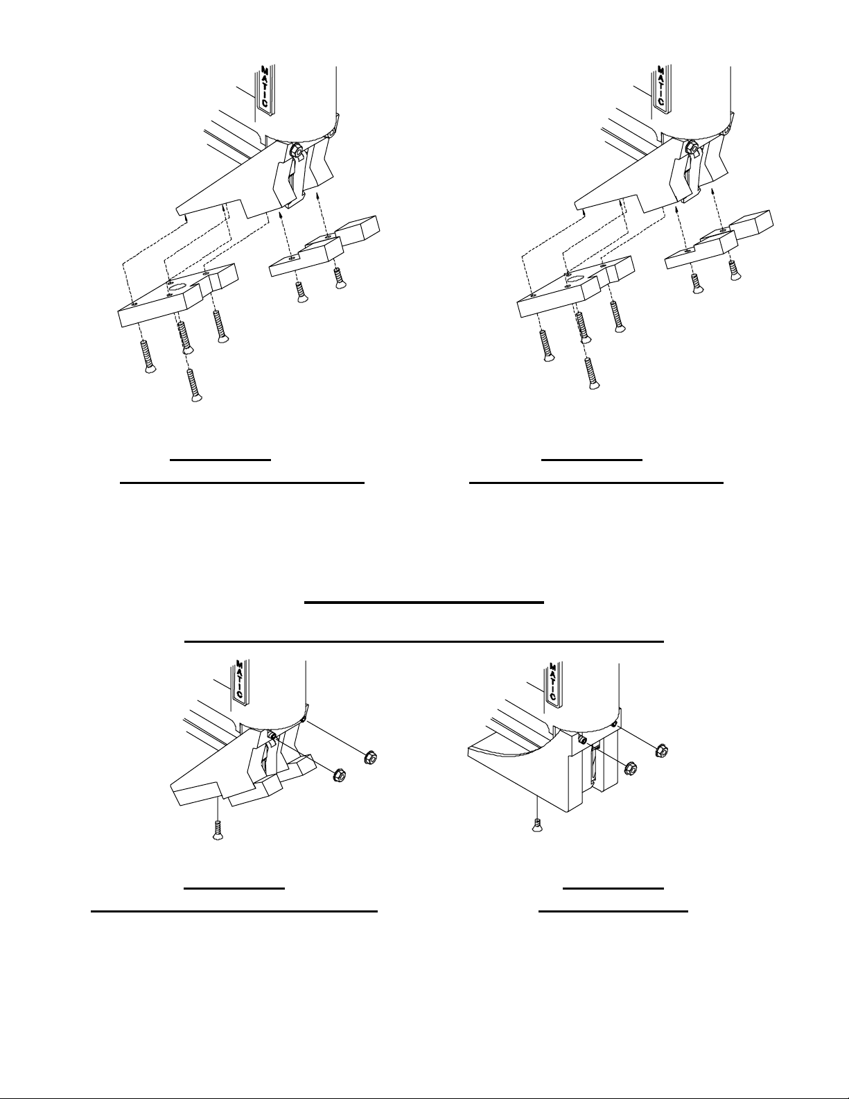
FIGURE 3
FIGURE 4
Tongue Nailing 3/4” Flooring Tongue Nailing 9/16” Flooring
Shoe P/N 50125 Shoe P/N 50125
Shoe Base P/N 50115 Shoe Base and Pad
Shoe Pad P/N 50114 Accessory P/N 50246
SHOE CHANGING
CONVERSION TO AND FROM FACE NAILING
FIGURE 5
Tongue and Groove Flooring Shoe
Cat. No. 50111
Loosen or remove Flange Nuts (Ref. No. 33) with Wrench and Shoe Screw (Ref.
No. 50) to remove and change over from Tongue Nailing to Face Nailing Applications.
Change from Face Nailing to Tongue Nailing by loosening or removing Flange Nuts (Ref.
No. 33) with Wrench and Face Shoe Screw (Ref. No. 42).
5
FIGURE 6
Face Nailing Shoe
Cat. No. 50113
Page 6

Nailing Tongue And Groove Flooring
Using the PORTAMATIC® Nailer
Install the Face Nailing Shoe on the
1.
Section Pg. 5 Figure 6).
After squaring the Floor and allowing for expansion as recommended by the Wood
2.
PORTAMATIC
Flooring Industry (NWFA, NOFMA and MFMA), place the grooved edge of the first
row of Flooring towards the wall on the side of the room from which you are starting.
Be careful to use the Brown Cap of the Hammer to hit the Ram Head of the
3.
®
PORTAMATIC
Nailer and the Gray Cap on the Flooring. Using the Brown Cap to
hit the Flooring will destroy the Cap.
Depress Safety Trigger, and strike Ram Head of the
4.
Face Nailing Shoe installed.
After striking the Ram Head, the actuating cycle of the
5.
drives one nail into the Flooring.
When the nail has been completely driven, the
6.
PORTAMATIC
automatically reset, and is ready to be moved to the next position and drive another
nail.
Be careful not to drive one nail on top of another. Damage to the Nailer might result or
7.
injury from sparks or a sliver of metal that might break away if this should occur.
If a nail is driven on top of another or a jam occurs, refer to the “Clearing a Jam”
8.
section of the manual on page 9.
Slide the
9.
PORTAMATIC
®
Nailer along the Flooring to the location at which you
desire to drive the next nail.
Continue until four (4) rows of Flooring have been Face Nailed.
10.
Remove the Face Nailing Shoe Accessory from the
11.
install the Tongue and Groove Nailing Shoe
Place the groove of the fifth row of Flooring over the tongue of the fourth row of
12.
(See
Flooring and tighten using the Hammer. Depress Safety Trigger, and strike Ram Head
of the
Slide the
13.
PORTAMATIC
PORTAMATIC®
®
Nailer with the Tongue and Groove Nailing Shoe installed.
Nailer along the tongue of the Flooring to the location at
which you desire to drive the next nail.
Continue Step 11 until you have completely nailed all but the last five (5) rows of
14.
Flooring.
Remove the Tongue and Groove Nailing Shoe from the PORTAMATIC Nailer and
15.
install the Face Nailing Shoe (See
Install and nail in place the remaining five (5) rows of Flooring using the
16.
®
PORTAMATIC
Nailer with the Face Nailing Shoe installed.
Shoe Changing
®
Nailer
PORTAMATIC
(See
Shoe Changing
®
PORTAMATIC
®
Nailer will
PORTAMATIC
Shoe Changing
Section Pg. 5 Figure 5).
®
Section Pg. 5 Figure 6).
Nailer with the
®
Nailer
Nailer and
6
Page 7
Operating Instructions
Safety Requirements
1. WEAR SAFETY GLASSES
2. NEVER
3. USE ONLY
Air supply hoses should have a minimum working pressure rating of 150 PSI or 150
4.
use a Hammer with a loose head or splintered handle.
nails from Porta-Nails, Inc.
percent of the maximum pressure produced in the power source, whichever is higher.
Check all hoses before connecting to ensure that they are free from dirt, grit, or
5.
particles that could alter the performance of the tool.
An airline Filter and Regulator are required.
6.
7.
The
PORTAMATIC
®
pneumatic Nailer requires
and safety shoes for protection against foreign objects.
DO NOT USE
Clean, Dry Air
.
IN-LIN E OILERS WITH THE PORTAMATIC
®
Dust, dirt and other particles
.
in the system can cause premature wearing of the major components. Cylinder, piston,
and o-rings are especially sensitive to wear caused by dirt abrasion.
Adjust the airline Regulator to
8.
90-95 PSI
. Be sure that the tool is not pointed at you or
others when it is connected to the air supply source.
Note:
Some materials may require a higher pressure of 95-100 PSI in order to
countersink the nail.
9. NEVER
use a defective tool. Replace worn or damaged parts immediately. Be sure
that the Safety Trigger and operating mechanisms operate correctly and that all screws
and seals are securely tightened at all times.
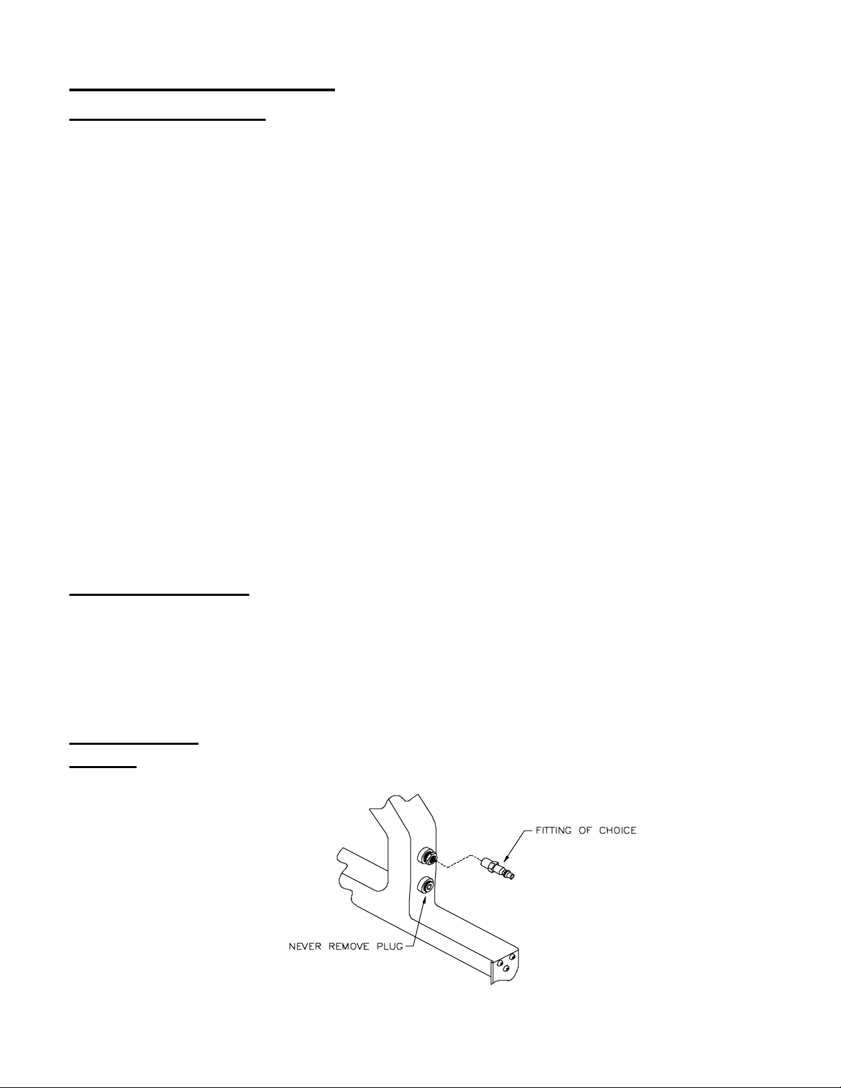
Installing A Fitting
Before using the
PORTAMATIC®
PORTAMATIC
Nailer has an adapter installed to accept a 3/8” NPT fitting. This
provides the owner the advantage of installing the preferred 3/8” NPT Fitting of choice.
This allows the freedom to use any configuration of quick connect 3/8” NPT Fitting.
Install the 3/8” NPT Fitting into the supplied adapter and gently tighten.
IMPORTANT:
NEVER
be removed. If plug is removed, the
The bottom hole of the
correctly and serious damage may occur.
®
Nailer, a 3/8” NPT Fitting must be installed. The
®
PORTAMATIC
PORTAMATIC
that is plugged should
®
Nailer will not perform
7
Page 8
Loading the Tool
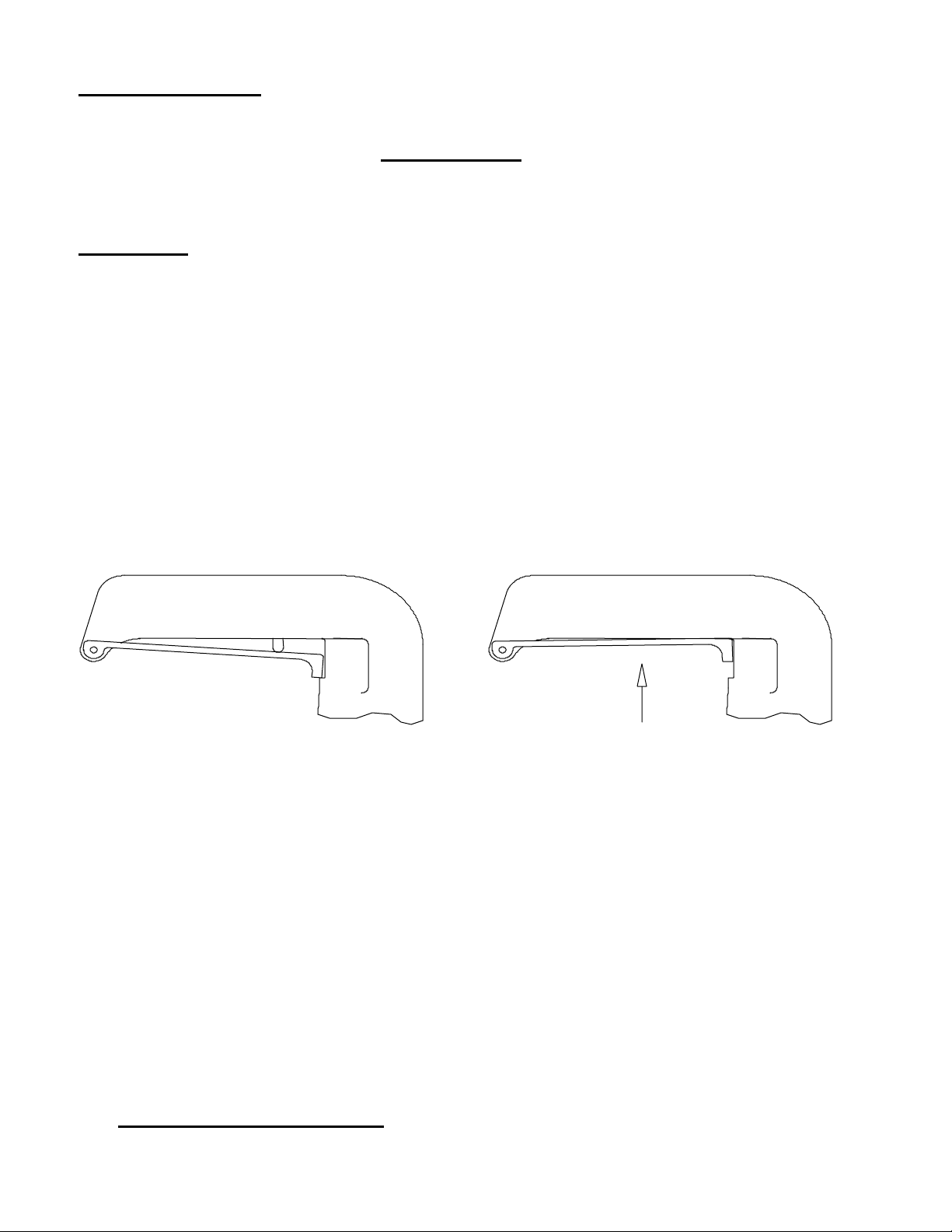
Insert nails into the nail track and pull back the Pusher Bracket (Ref. No. 19 Pg. 17) to
provide pressure against the nails.
IMPORTANT!
For proper operation, never use the
PORTAMATIC® Nailer with less than a 2 inch stack of nails remaining in the nail
track.
Operation
After connection with power source is made, check to be sure that the airline
1.
Regulator pressure is
90-95 PSI. Note:
of 95-100 PSI in order to countersink the nail.
Ensure that tool is in proper working order and that there is no leaking of air. If there
2.
is an air leak,
of Owner’s Manual.
After being sure tool is operable, place tool in position to be used. Always place the
3.
Disconnect Immediately
tool in proper position against the Flooring to be nailed before striking the Ram.
4.
The
PORTAMATIC
®
Nailer has a Safety that prevents accidental firing if Ram Cap
is hit while connected to power source. Squeeze Safety Lever to enable the Nailer.
Releasing the Safety Lever re-engages the Safety and renders the Nailer in operable.
Some materials may require a higher pressure
! Refer to the Repair and Maintenance section
To operate tool, depress Safety Trigger while tool is in position of use, and strike the
5.
Ram Cap (Ref. No. 47 Pg. 17).
If on the first initial operation a nail does not eject into the Flooring, repeat Hammer
6.
blow. This will ensure that the Driver Blade/Piston is properly reset to allow the
Driver Blade/Piston (Ref. No. 36 Pg. 17) to be in the correct position to drive the nail.
7. DO NOT OVERPOWER THE NAILER
– A minimal stroke of the hammer will
fire the Nailer. If the Flooring is warped or bowed, the Ram can be hit firmly to
tighten the Flooring. Try to avoid this constant wear, as abusive blows by the hammer
could damage tool.
8. Note:
The
PORTAMATIC
®
Nailer will not drive a nail if the Ram Cap is struck by
Hammer and the Safety Trigger is not depressed.
9.
The
PORTAMATIC
®
Nailer is user-friendly and following these simple
instructions, will insure a very high quality Hardwood Flooring installation.
If the nail is not properly seated, increase pressure incrementally until nail is seated.
10.
DO NOT EXCEED 110 PSI!
8
Page 9
Clearing A Jam
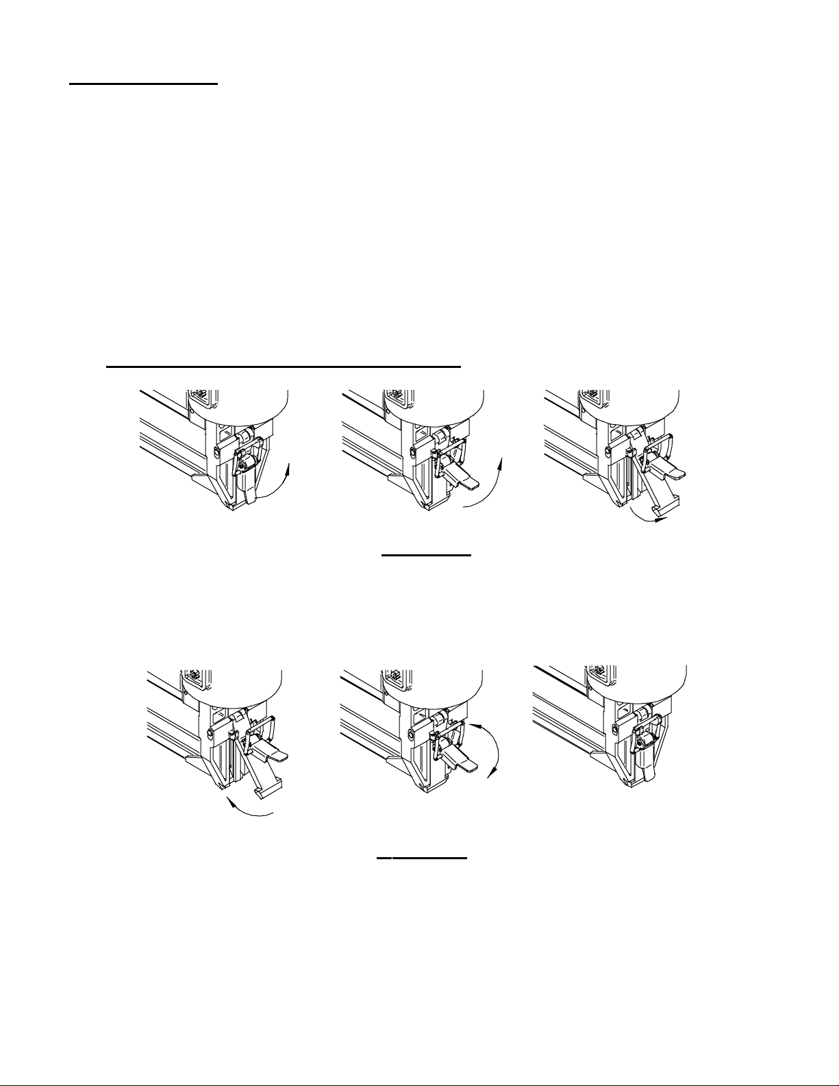
In the event of a jam, the Gate (Ref. No. 22 Pg. 17) can be opened by pulling the gate
1.
clip upward. (See Figures 7 and 8) (The Shoe does not have to be removed to open
and close the Gate.)
2. IMMEDIATELY DISCONNECT
Once Gate is open, clear jam.
3.
Inspect to be sure no damage has been done to the Driver Blade, Guide, Gate,
4.
Magazine or Pusher Finger. (If damage has occurred, repair immediately before
connecting to the power source and continuing.)
Close Gate by placing the Gate Clip Wire over the two hooks of the Guide as shown
5.
and press down to seat and lock the Gate in place. Make sure the Gate is properly
reseated.
6. DO NOT OPERATE WITH GATE OPEN!
from power source until jam is cleared!
Figure 7
Pull the tab of Gate Clip to open Gate. Opening
the G ate allows access to the Nail Chamber.
Figure 8
To Close Gate, reset the Gate tab ends under the ears of
the Guide. Reset the Gate Clip Wire over the two hooks
of the Guide and pivot Gate Clip down until seated.
Ensure Gate is secure before continuing operation.
9
Page 10
Repair and Maintenance
IF AIR IS LEAKING FROM THE NAILER DISCONNECT IMMEDIATELY!
If air is leaking from the Nailer, inspect to make sure Main Housing or Extension
Handle is not cracked or damaged. If Main Housing and Extension Handle are not
damaged, the head gasket or an O-Ring may need to be replaced. Refer to Exploded view
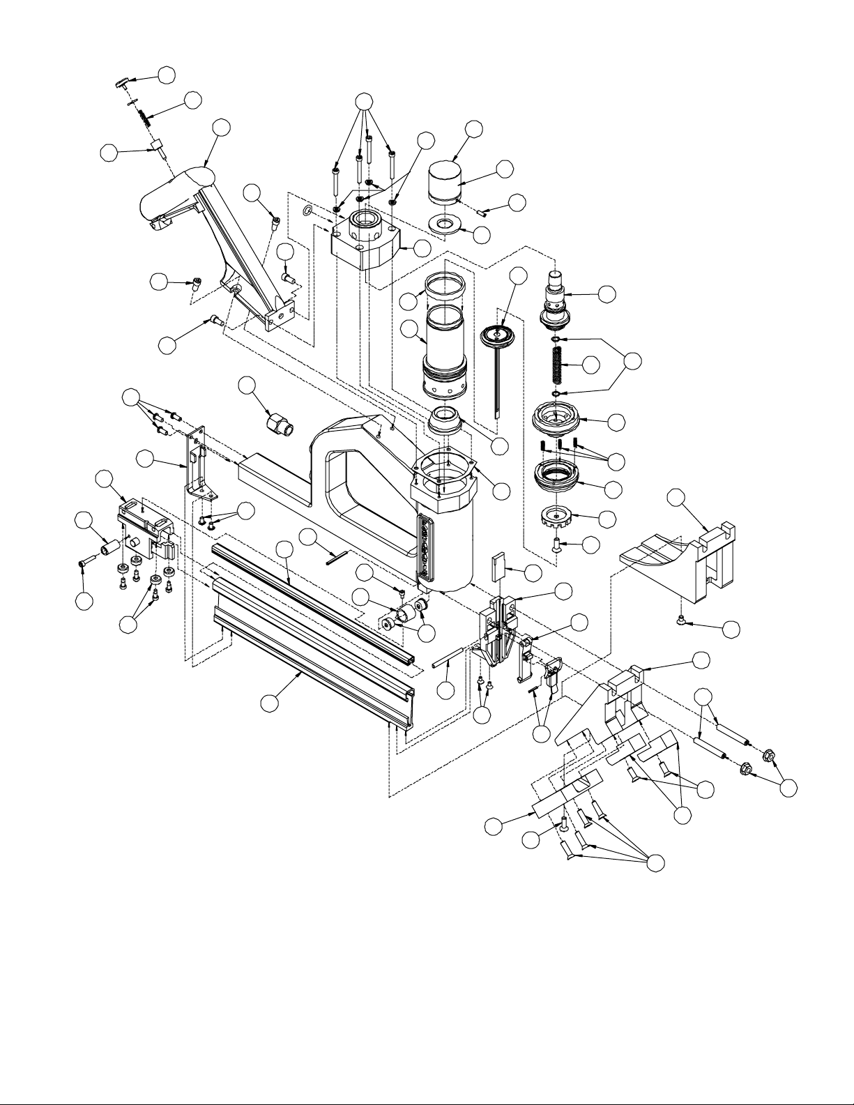
Page 17 for Disassembly.
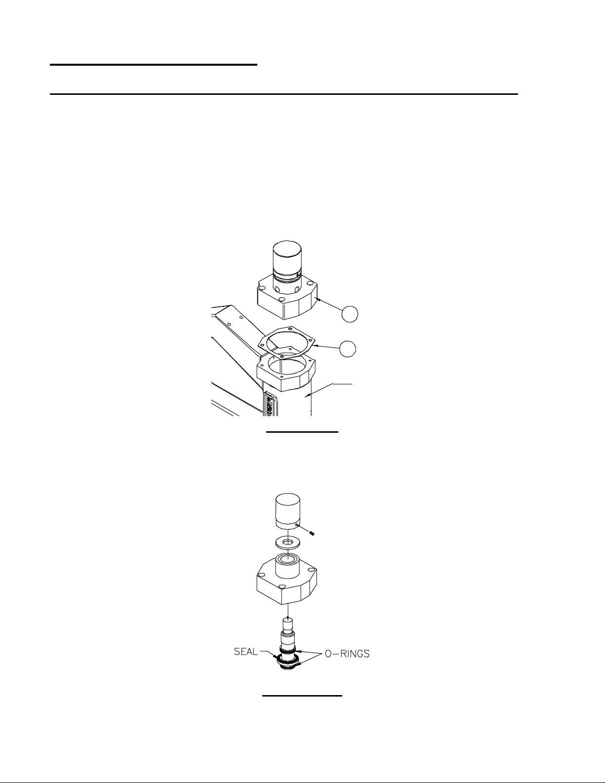
1. Remove Extension Handle (Ref. No. 15 Pg. 17) from Main Body and Main Valve
Housing (Ref. No. 46).
2. Remove Main Valve Housing Screws (4) and remove Main Valve Housing.
3. Check the Head Gasket (Ref. No. 6) to ensure proper positioning and/or check for a
tear or pinched edge around the screw holes.
46
6
MAIN
BODY
FIGURE 9
If Head Gasket does not look damaged, check Main Valve Upper and Lower O-Rings
4.
and Seal. Remove Ram Head Set Screw and inspect. Replace if O-Ring is broken or
flattened in one or more spots. Refer to Figure 11 in the “Replacing O-Rings” section.
FIGURE 10
10
Page 11
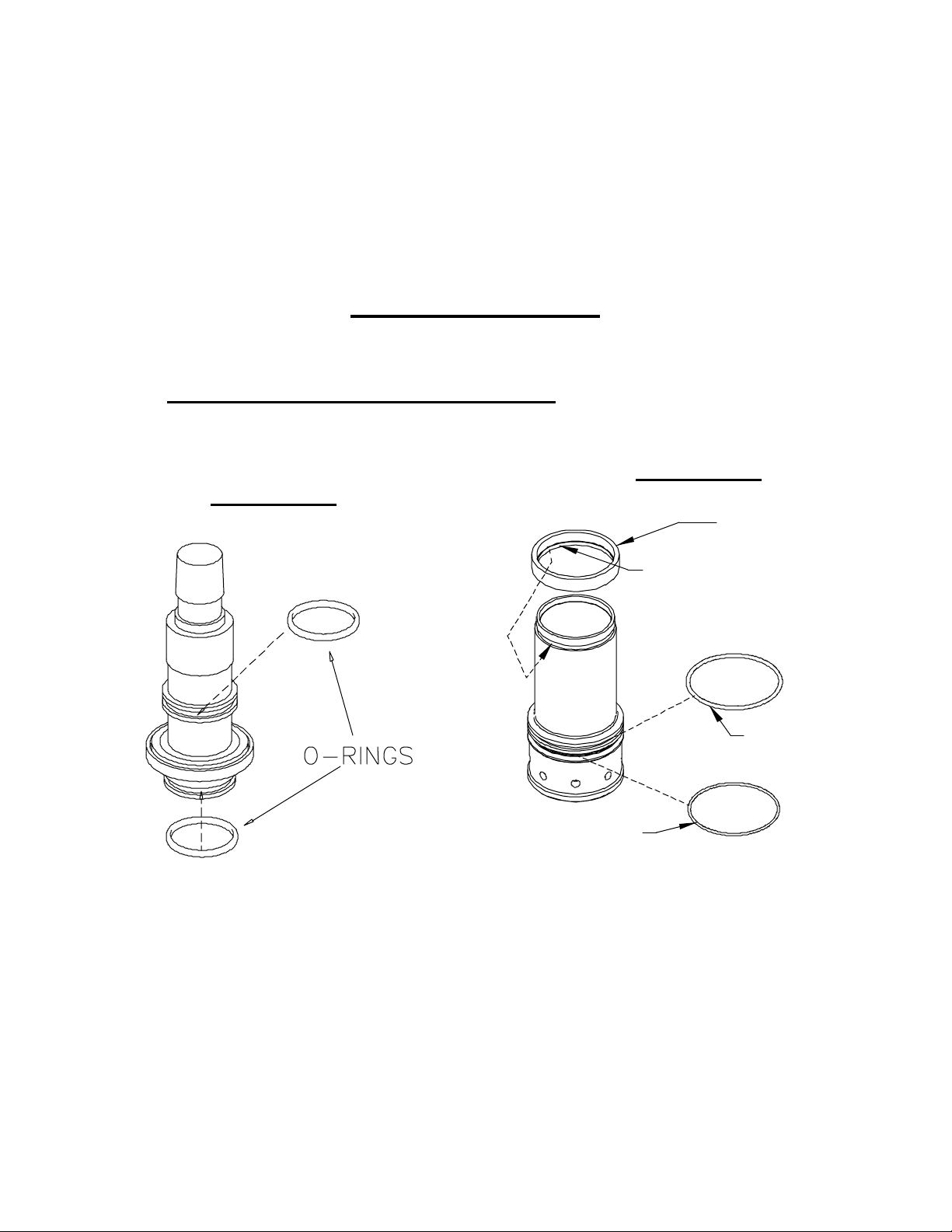
If the Seal is damaged or has separated from the Main Valve, replace Main Valve. The
Seal and Main Valve have been assembled permanently at the Manufacturing Facility
and can not be repaired in the field.
5. Inspect other O-Rings as described in “Replacing O-Rings” section Figures 12-16 to
ensure proper positioning and distortion has not taken place. If any of the O-Rings are
distorted, refer to the proper Figure and replace.
6. After inspecting and/or replacing O-Rings, assemble Nailer and connect to power
supply.
Replacing O-Rings
Use Texaco Molytex® EP 2 Grease or equivalent. Do not use greases that cause ORings to swell. The use of these types of greases may prevent Nailer from operating
properly.
NEVER USE OIL FOR LUBRICATION!
FIGURE 11
Main Valve
FIGURE 12
Cylinder
TOP CY LINDER
CUSHION
O-Ring is used both on the upper groove
as well as the lower groove. The flat seal
in the middle can not be replaced. Grease
O-rings.
NOTE : INS IDE LIP OF TOP CY L INDER
CUSHION SHOULD BE INSTALLED
IN GR OOVE OF CY L INDER.
SEA LING G ROOVE
O-RING
CHA R GE HOL E
O-RING
Top O-Ring is used on the sealing groove.
Bottom O-Ring is used on the groove
with the charging holes. Grease O-rings.
Top Cylinder Cushion should be
positioned as shown with the inside Lip
installed in the top Groove of the
Cylinder. Cushion Lip should be securely
“seated” in groove.
11
Page 12
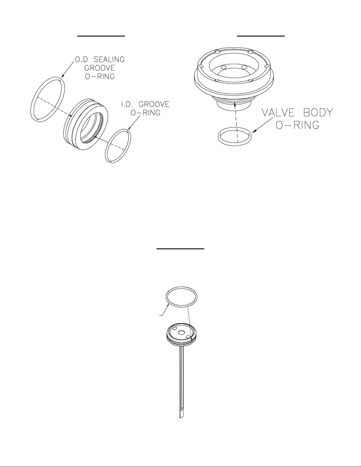
FIGURE 13
Cylinder Discharge Valve
O-Ring is used on the O.D. sealing
groove. O-Ring is used on the I.D. groove
of the Cylinder Discharge Valve. Grease
O-rings.
FIGURE 14
Valve Body
O-Ring is used on the sealing groove of
the Valve Body. Grease O-ring.
FIGURE 15
Driver Blade & Piston Assembly
O-Ring is used on the sealing groove of the Piston. Grease O-ring.
O-RING
12
Page 13
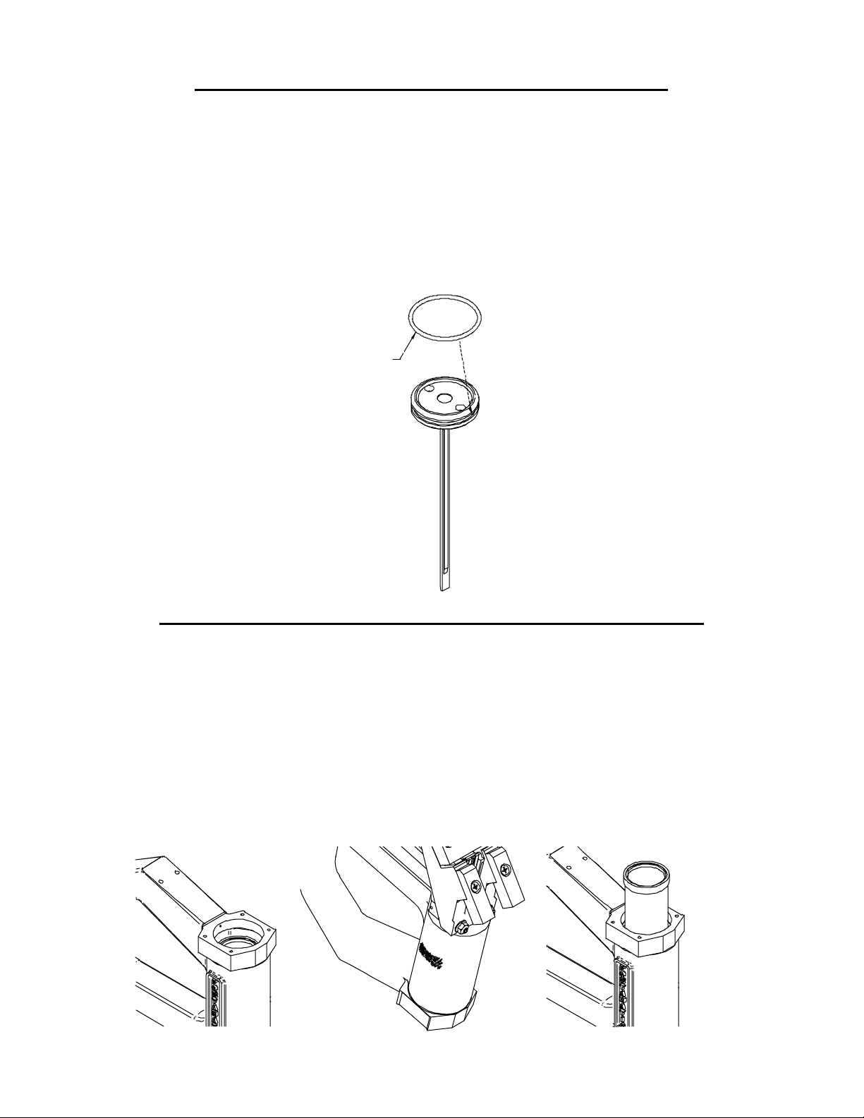
Replacing the Driver Blade/Piston Assembly
1. Remove Extension Handle from Main Body and Main Valve Housing.
2. Remove Main Valve Housing Screws (4) and remove Main Valve Housing.
3. Remove Piston Assembly from the Cylinder.
4. Check that the Driver Blade is tightly held and does not move freely.
5. Apply Molytex MP2 Grease or equivalent to the O-ring around the piston.
USE OIL FOR LUBRICATION
.
NEVER
6. When assembling the Driver Blade and Piston in the Cylinder, be sure the Beveled side
of the Driver Blade faces the Magazine Side of the Guide.
O-RING
Removing and Re-Installing the Cylinder Assembly
1. After removing the Extension Handle and Main Valve Housing, remove the Head
Gasket, Valve Body Assembly and the Piston Assembly.
2. Turn the Nailer over and tap lightly on a hard surface carefully insuring not to damage
the Body in anyway.
3. The Cylinder should dislodge enough to enable grasping and removing.
4. To replace the Cylinder,
grease O-rings
in the bottom of the Cylinder and push the Cylinder back down into the Body.
5. Push Cylinder down to reseal the external O-ring in the Body and ensure the Cylinder
and Piston Cushion are seated at the bottom of the Body.
and make sure the Piston Cushion is installed
15
Page 14
ACCESSORIES
The testing of this tool has been accomplished with the following accessories. For safest
operation, it is recommended that only these accessories be used with this product.
WARNING
product; use of such accessories could be hazardous.
- Since accessories other than those listed have not been tested with this
REF. PART
NO. DESCRIPTION
NO.
Not Shown 50104 O-Ring Repair Kit
Not Shown 50172 Grease
Not Shown 50250 Shoe Base & Pads for 33/32” Flooring
Not Shown 50246 Shoe Base & Pads for 9/16” Flooring
Not Shown 50139 Hex Wrenches
Not Shown 50318 Wrench – Shoe / Body Flange Nuts
Not Shown 50039 Hammer (Brown Cap for Ram Head, Gray Cap for Floor)
Not Shown 50299 Hammer Cap (Brown)
Not Shown 50170 Safety Glasses
Not Shown 50038 Case -
PORTAMATIC
®
Not Shown 42623 Porta-Nails 10 packages of 1000 2” Nails
Air Compressor -
1-1/2 HP, approximately 5CFM at 100 PSI. An airline Pressure
RECOMMENDED EQUIPMENT
Regulator set at 90-95 PSI should control line pressure. Air Compressor must have a
Condensate Drain at bottom of Accumulator Tank. Drain every 24 hours or after
every day’s use.
PORTAMATIC.
DO NOT USE OIL LUBRICATOR WITH THE
!"There should be an Air-Line Filter between the Pressure Regulator and the Air
Compressor. Filter on Air-Line must be drained after use every day.
- 100’ – 3/8” I.D.
Hose
Fitting
- 3/8” NPT
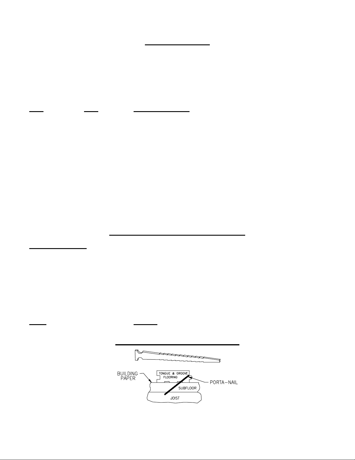
USE OF THE Porta-Nail
The Porta-Nail is 2” long and the PORTA MAT IC® with the standard shoe drives the nail into the to ngue and
groove flooring at a 45-degree angle. T he orientation of the nail is a s depic ted in wood floor joist construction.
14
Page 15

REF. PART
NO. DESCRIPTION
NO.
1. 1575 Screw–Handle/Valve Housing (2 ea.)
2. 1589 Screw – Handle / Body (2 ea.)
3. 50280 Washer – Return Spring
4. 50010 Screw – Shoe / Body (2 ea.)
5. 50294 Cylinder Cushion Ring
6. 50012 Head Gasket
7. 50013 Cylinder Exhaust Valve
8. 50018 Spring - Return
9. 50019 Spring - Discharge (3 ea.)
10. 50020 Piston Cushion
11. 50023 Discharge Valve & O-Rings
12. 50025 Cylinder & O-Rings
13. 50015 Valve Body & O-Ring
14. 50431 Gate Clip & Pin
15. 50160 Extension Handle Assembly W/Safety (Includes 39,40,45)
16. 50402 Pusher Pull Screw
17. 50062 Spring - Constant Force & Screw (Ref. 18)
18. 50064 Screw – Constant Force Spring
19. 50413 Pusher Assembly (Includes 16,25,38)
20. 50067 Spring Spool (2 ea.)
21. 50102 Guide Assembly (Includes 14,25,38)
22. 50080 Access Gate
23. 50327 Restricter Plate
24. 50085 Dowel Pin – Gate / Guide
25. 50403 Pusher Wheels & Screws (4 ea.)
26. 50158 Rail
27. 50090 Magazine Retainer Bracket
28. 50098 Magazine
29. 50101 Screws – Magazine / Bracket (2 ea.)
30. 50103 Ram Washer
31. 50114 Shoe Base Pad - 3/4 Flooring (2 ea.)
32. 50115 Shoe Base - 3/4 Flooring
33. 50320 Flange Nut – Shoe / Body (2 ea.)
34. 50125 Shoe – Angled
15
Page 16

35. 50126 Screws – Valve Housing / Body (4) W/ 4 Washers (Ref. 44)
36. 50330 Piston / Driver Blade & O-Ring Assembly
37. 50134 Spring Pin – Constant Force Spring / Spools
38. 50415 Knurled Pusher Pull
39. 50140 Safety Stem
40. 50142 Cover – Safety
41. 50152 Main Valve Assembly & O-Rings
42. 50177 Screw – Face Shoe
43. 50154 Screws – Magazine / Retainer Bracket (3 ea.)
44. 50155 Washers – Valve Housing Screws (4 ea.)
45. 50161 Spring – Safety
46. 50162 Valve Housing Assembly
47. 50163 Ram Head Assembly W/Cap & Screw (Ref. 52 & 54)
48. 50113 Face Shoe
49. 50164 Screws – Guide / Magazine (2 ea.)
50. 2503 Screws – Shoe / Magazine / Cylinder Exhaust Valve (4 ea.)
51. 2600 Screws – Shoe Base (4 ea.)
52. 9005 Screw – Ram Head / Main Valve
53. 50281 Hex Adapter –3/8 NPT (Female) x 3/8 NPT (Male)
54. 40030 Ram Cap – Rubber
16
Page 17
40
45
15
39
2
1
2
1
43
27
19
38
16
25
53
29
37
26
35
44
46
5
12
18
17
20
47
54
52
30
36
41
3
8
13
10
9
6
23
21
11
7
50
22
48
42
34
28
24
49
14
32
50
51
4
50
31
33
17
Page 18
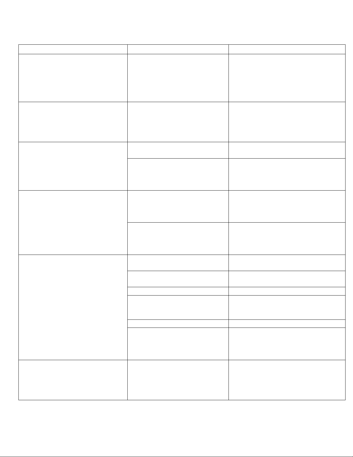
421 PORTAMATIC®
TROUBLE SHOOTING
PROBLEM OR QUESTION CAUSE CORRECTIVE ACTION
Nailer is Jamming
Nailer is not always firing a nail
Air is escaping
Nailer is shooting two nails.
Nails are not being counter sunk
into wood and are left sticking out
of wood.
Nailer does not fire when trigger is
pulled.
More than one Nail trying to get
into chamber.
Obstruction keeping the nail clip
from advancing.
Damaged or worn seal. Determine location of air escaping.
Oil has been used causing ORings to swell which can restrict
movement of piston or other
component that must seal.
End of Rail is worn Turn Rail (Ref. #26) around to use
Screws holding Magazine (Ref.
#28) may be loose preventing
Rail (Ref. #26) from being held
properly in place.
Not driving Nails into the tongue
area
Tip of Driver Blade (Ref. #36)
broken
Air pressure too low Set air pressure to 90-95 PSI
Using air compressor that is too
small
Using an air line that is too small Always use 3/8” ID air line.
The Piston Cushion (Ref. #10)
could be damaged preventing the
Piston (Ref. #36) from
completing full stroke.
This is a safety feature The Nailer is not supposed to fire when
Check Rail (Ref. #26) for wear on the
end. If worn, turn rail around to use
other end in Guide or replace the rail.
Make sure pusher provides positive
pushing force on the nail clip to prevent
nails from turning.
Clear obstruction, trash, bent or twisted
nails, etc.
Make sure Pusher provides positive
pushing force on the Nail clip to
prevent Nails from turning
Replace appropriate seal.
Clean internal components. Check for
damaged seals or O-Rings. Replace
damaged seal or O-Ring. Grease as
specified in Owner’s Manual.
other end in Guide if this has not been
previously done. If Rail has already
been turned previously, replace Rail.
Tighten Screws (Ref. #49, #29) that
secure the Magazine (Ref. #28) to the
Guide (Ref. #21) and the back
Magazine Retainer Bracket (Ref. #27).
Always drive Nails into the tongue
area, not the groove.
Check Driver Blade (Ref. #36) and
replace if tip is broken.
Follow recommendations in the
Owner’s Manual relative to size and
volume of air compressor
Check Piston Cushion (Ref. #10) and
replace if needed.
the Trigger is pulled. In order to fire
the Nailer, the Trigger must be pulled
and the Ram Head (Ref. #47) struck
with the hammer, in that order.
18
Page 19
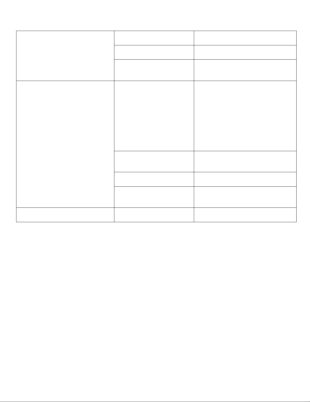
Ram is stuck in down position
Tool partially fires when air hose is
connected
Nailer partially fires when trigger
is pulled and before Ram is struck
Driver Blade (Ref. #36) could
be bent
Oil could have been used in
the tool
Cylinder Cushion Ring (Ref.
#5) could be loose or
damaged
Main Valve (Ref. #41) is not
seating in Valve Housing
(Ref. #46).
O-Rings on the Discharge
Valve (Ref. #11) may be
damaged.
Discharge Valve Springs
(Ref. #9) not aligned
Cylinder Exhaust Valve
Screw (Ref. #50) may be
loose.
Main Valve Lip Seal (Ref.
#41) is not sealing
Check and replace if needed.
Clean, replace O-Rings and grease as
recommended in the Owner’s Manual
Check Cylinder Cushion Ring (Ref. #5)
and replace if loose or damaged
Check the Return Spring (Ref. #8)
under the Main Valve (Ref. #41) to
make sure it is not damaged and that
the Return Spring Washers (Ref. #3)
are not damaged. Replace if needed.
Check for smoothness and free
movement of the Main Valve (Ref.
#41) in the Valve Housing (Ref. #46).
If too tight, replace the O-Rings on the
Main Valve.
Check and replace if needed.
Check and re-align if needed.
Check and tighten if needed. Use
LOCTITE® 242 (Blue) on screw.
Check Lip Seal. If damaged, replace
Main Valve (Ref. #41).
19
 Loading...