

Page 1

PORT-A-COOL®
®
manufactured by port-a-cool, llc
Series 2000
OWNERS MANUAL
for Hazardous Location Units
U.S. Patent 6,223,548
U.S. Patent D 362,905
U.S. Patent 6,502,414
FOR ELECTRIC MODELS
PAC2K36EP
PAC2K48EP
Page 2

Page 3
PORT-A-COOL®
Evaporative Cooling Units
OWNERS MANUAL
FOR
HAZARDOUS LOCATION MODELS
PAC2K36EP AND PAC2K48EP
(BUILT TO: CLASS I, GROUP C & D)
I. INTRODUCTION
A. What is evaporative cooling?
B. Humidity and Evaporative Cooling.
C. Evaporative Cooling and the
PORT-A-COOL® unit.
II. SETUP
A. Unpacking the
B. Removing the Cooling Pads.
C. Connecting the Water and Electricity.
III. OPERATING INSTRUCTIONS
A. Placement of the
B. Filling with Water.
C. Starting the Pump and Adjusting the Water Flow.
D. Starting the Fan.
IV. MAINTENANCE AND STORAGE
A. Daily Maintenance
B. Weekly Maintenance
C. Storage
V. TROUBLESHOOTING
A. Troubleshooting
VI. REPLACEMENT PARTS
A. Ordering Replacement Parts.
B. RMA Procedures
C. Port-A-Cool® Unit Limited Warranty
PORT-A-COOL® unit.
PORT-A-COOL® unit.
Page 4
I. INTRODUCTION
The PORT-A-COOL® unit is a fully self-contained, portable, high efficiency
evaporative cooler that is proudly made in America
at our factory located in Center, Texas.
A. What is Evaporative Cooling?
When trying to understand evaporative cooling, it may be best to think of air as being like a sponge, in
that regard, air has an ability to absorb moisture that it comes in contact with. The amount of moisture that the
air will absorb depends on the state of the air, or specifically, how much moisture the air already contains and
the temperature of the air. If the air is warm and contains only a small amount of moisture, it will more readily
absorb moisture. As air cools, its volume decreases, and with it, its ability to absorb moisture decreases.
The term “relative humidity” describes the quantity of water in the air in relation to its total capacity.
Any volume of air at any given temperature has an ability to hold a certain quantity of moisture. If the air contains 20% of its total capacity to hold moisture, the relative humidity is said to be 20%. Whereas, a humidity of
100% indicates that the air at this temperature and pressure is holding all the moisture it can. If the air has less
that 100% relative humidity when entering the PORT-A-COOL® unit, then it has the ability to hold more moisture,
and will thus evaporate more water and cool more effectively.
When describing the amount of moisture in the air, the term relative humidity is used because the
absorption capacity of air changes relative to air temperature. The warmer the air, the more absorbant it
becomes, and can consequently hold more water. That is to say that air that has a 100% relative humidity
can hold no more water vapor. However, if the air is heated, it expands, and as a result the relative humidity
decreases even though the total amount of water vapor in the air has not changed. As a result, we must describe
the level of humidity relative to its maximum capacity. Is it a 50˚F sponge or an 80˚F sponge? An 80˚F sponge
will hold more water at 50% humidity than a 50˚F sponge.
How is cooling produced? In order to evaporate water, heat (energy) is required. In fact, the evaporation of one gallon of water requires almost 8,700 BTU’s. Where does this heat come from? The heat comes from
whatever the water is in contact with as it evaporates. This could be a hot sidewalk, your body, a tree, or from
the air itself. As the heat is removed from an object, the temperature of that object is decreased. In the case of
the PORT-A-COOL® unit, heat is removed from the air, reducing the temperature of the air.
It is important to realize that the temperature of the water does not have a great effect upon the cooling
produced by the evaporation. If you were to place a gallon of 50˚F water on a warm sidewalk, it would consume
9,000 BTU’s during its evaporation, thus making the sidewalk 9,000 BTU’s cooler. A gallon of 90˚F water would
produce 8,700 BTU’s of cooling, only a 3 percent difference in the total result. This translates into a difference of
less than 1˚ F in the performance of a PORT-A-COOL® unit.
*
PORT-A-COOL® Hazardous Location Units
Page 5
The following table demonstrates the BTU’s removed from the air based on a given amount of water
evaporated in an hour by the PORT-A-COOL® unit.
U. S. Gallons / Hour Total BTU’s Removed
10 (37.8 liters or 8.3 Imperial Gallons) 87,000
12 (45.4 liters or 10.0 Imperial Gallons) 104,400
14 (53.0 liters or 11.7 Imperial Gallons) 121,800
For actual temperature drops refer to Appendix A.
In simple terms, evaporative cooling is nature’s way of cooling. The PORT-A-COOL® unit utilizes the
same phenomenon, but in an extremely efficient manner.
B. Humidity and Evaporative Cooling.
A given volume of air at a certain temperature and pressure has the ability to absorb and hold a certain
amount of water vapor. If that volume of air contains 50% of the amount of moisture that it is capable of holding,
it said to be at 50% relative humidity. The higher the temperature of the air, the higher the amount of moisture it
is capable of holding. Any change in the temperature without a corresponding change in the pressure results in
an increase or decrease in the amount of water vapor the air can hold.
If the temperature increases without an increase in the pressure, the result is a decrease in the relative
humidity, and thus an increase in its ability to hold moisture. That is to say that in the morning the humidity
may be high, but as the day passes and the temperature increases the relative humidity will naturally decrease.
The extent to which relative humidity decreases through the day can be affected by local weather systems and proximity to large bodies of water. If an increase in temperature accompanied by a weather system
containing moisture moves in, then the drop in humidity will not be as great. Nevertheless, the fact remains that
relative humidity does drop as air temperature increases. In fact, for every 20˚F rise in temperature, the moisture-holding ability of air doubles. For instance, if the temperature of the air was 70˚F and the relative humidity
was 100% at 5 a.m., and the temperature increased to 90˚F at noon, the moisture holding ability of the air would
double.
As a result, the air would now be holding only half of the moisture it is capable of holding, and the relative humidity of the air would drop to 50%.
The hotter the day, the drier the air becomes, and the more cooling that can take place through the
evaporation of water. This means that when the day gets hot enough to require cooling, the relative humidity
will be much lower than in the morning and will allow an evaporative cooling device to work more effectively.
Since any evaporative cooling device must evaporate water to achieve cooling, more water vapor is put
into the air. As the ambient relative humidity increases, it becomes more difficult to put moisture into the air.
The efficiency of any evaporative cooling device is directly related to its ability to evaporate water (cooling the
air) at a given relative humidity. A unit with low efficiency will cool only at low relative humidity levels, while a
unit with high efficiency can achieve effective cooling at much higher humidity levels.
PORT-A-COOL® Hazardous Location Units
*
Page 6

C. Evaporative Cooling and the PORT-A-COOL® unit.
The PORT-A-COOL® unit is the state-of-the-art, high efficiency, portable evaporative cooling system that
utilizes high efficiency KüüL® brand, rigid cooling media, manufactured with the patent pending “thru-cure” ™
process.The PORT-A-COOL® unit’s unique patented housing enclosure, along with the KüüL® brand high efficiency cooling media, allows the unit to cool effectively in very high relative humidity conditions. Conditions that
other portable evaporative cooling devices, such as the old style “swamp coolers”, cannot approach.
The public has an initial tendency to equate the PORT-A-COOL® unit with the “swamp cooler,” types
of evaporative coolers and, in reality, the only thing that they have in common is that they are both evaporative coolers, much as the 1973 model automobile and 2001 model automobile are both cars. The key to efficient
evaporative cooling is using a specially designed, high efficiency, rigid cooling media contained in a properly
designed housing to insure effective directing of the air over the water saturated media at the proper velocity.
The PORT-A-COOL® unit has incorporated all of these features and more.
As explained in PART B of this section, the effectiveness of the PORT-A-COOL® unit is best appreciated when
it is above 85˚F and below 75% relative humidity. By the time the outside temperature reaches 85˚F, the humidity is
almost always below 75%. Generally, as one goes up, the other goes down.
For actual temperature drops refer to the charts of Appendix A.
*
PORT-A-COOL® Hazardous Location Units
Page 7
I. SETUP
A. Unpacking the PORT-A-COOL@ unit.
The PORT A-COOL HAZARDOUS LOCATION MODELS (PAC2K36EP and PAC2K48EP) are shipped strapped to
a plastic pallet with a large cover box strapped over the PORT-A-COOL® unit. It is a simple matter to cut the strap
and remove the box by lifting it over the PORT-A-COOL® unit. This will expose the plastic dust cover. Remove the
dust cover. At this time two (2) people can remove the PORT-A-COOL® unit from the pallet. Due to the additional
weight of the unit caution should be taken in removing the unit.
B. Removing the cooling media. (Disconnect Power)
Caution- Disconnect power before performing this operation!!
The PORT-A-COOL® unit should now be exposed to allow removal of the cooling media (pads). The front
flap must be removed to allow access to the cooling pads. Start with the center pad, which should be tilted out from
the top and lifted out of the drain trough. The two pads to either side of the center pad may then be removed in
the same manner. Should you desire to remove the two outside pads, they must first be pulled sideways toward the
center of the PORT-A-COOL® unit until they clear the side retainer. They may then be removed as the other pads.
Removal of the pads allows for inspection of the interior of the unit. Make sure all connections are tight and both
motor and pump are secure.
D. Connecting the water and electricity.
Water Connection (PORT-A-COOL® unit must be upright and on a level surface.)
After the PORT-A-COOL® unit has been thoroughly tested at the factory, the special female/female adapter
is connected to the brass bulkhead connector on the left side of the PORT-A-COOL@ unit (when looking at the fan
side). Simply attach a standard garden hose to the brass female/female adapter.
Verify that the rubber hose washer is in place before attaching, and tighten the fitting to guarantee that a
secure connection is made. Once the hose connection is made, water may be turned on to the PORT-A-COOL® unit.
Water should now be entering through the float valve to fill the sump tank.
To verify that your connections are well made, manually lift the red float in the float valve until it seats
against the top of the valve housing. The water flow should stop and the inlet connections may now be visually
checked for leaks, paying particular attention to the hose connection to the float valve and the connections to the
bulkhead fitting, these connection may loosen during shipment.
PORT-A-COOL® Hazardous Location Units
*
Page 8
Water supply inlet pressure should be limited to 50 psi maximum.
The cooling pads may now be replaced by reversing the removal operation above in Section I. Paragraph B.
Electrical Connection
PORT-A-COOL® unit must be upright and sitting on caddy with cooling pads installed!
These models utilize a single power cord and control switches. The power cord on this unit is 50’ of 14-gauge
3-wire grounded cord with out plug, so the unit can be wired to meet local code requirements. Check the chart below
to determine what the electrical requirements for your specific model may be. The use of separate multiple outlet
devices is not recommended.
When making electrical connections, insure that local and national codes are adhered to.
ELECTRICAL REQUIREMENTS
PORT-A-COOL® VOLTS MAX MAX
MODEL +- 10 FREQUENCY AMPS WATTS
PAC2K36EP 115 60 13.6 1200
PAC2K48EP 115 60 18.1 1750
*
PORT-A-COOL® Hazardous Location Units
Page 9
II. OPERATING PROCEDURES
A. Placement of the PORT-A-COOL@ unit.
PORT-A-COOL@ units should be used in well-ventilated areas only.
There are three primary considerations when deciding where to place the PORT-A-COOL® unit.
1) Fresh Air Supply -The rear of the unit (pad area) must be placed so to insure that
a smooth, uninterrupted supply of fresh air is available.
2) Air Pattern -The cool air discharged from the PORT-A-COOL® unit should have a clear
area to circulate in, as free of obstruction as possible.
3) Ventilation (Exhaust) -There should be a defined place in which the air from the
PORT-A-COOL® unit can be exhausted from the area being cooled. This is to prevent the
unit from recirculating air that has already been through the cooling process.
A primary consideration when actually deciding where to place PORT-A-COOL® unit is the direction of the
air flow. The PORT-A-COOL@ unit creates a fan-shaped air pattern that disburses the air over a large area. This pattern may be disturbed or broken up by obstacles such as shelves, work benches, etc. It is important to insure that a
clean, unbroken path for the air from the PORT-A-COOL® unit is provided to the maximum extent possible.
It may be desirable to raise the PORT-A-COOL® unit above any low obstructions in order to increase the
overall coverage. When raising the height of the PORT-A-COOL® unit, insure that the platform constructed for
holding the PORT-A-COOL® unit is stable, well constructed, and will not allow the PORT-A-COOL® unit to tip over.
The PORT-A-COOL® unit MUST be level on its base. When supporting with a platform, allow for the full weight of a
functioning PORT-A-COOL® unit by including the weight of the water both in the sump tank and the added weight
of the water-saturated cooling pads. The total weight could be in excess of 500 lbs. (227 kg.).
When the PORT-A-COOL® unit is placed near a wall or other obstruction, it is recommended that a distance of at least 3 feet from the wall or obstruction to the face of the cooling pads is maintained. This allows the
unrestricted flow of Warm air to the back of the PORT-A-COOL® unit. When using multiple PORT-A-COOL® unit
in close proximity, be sure to aim the PORT-A-COOL® unit so that the air flows compliment each other and not
oppose. Opposition will negate the air flow and allow an area of dead air to accumulate between two or more PORT-
A-COOL® units.
B. Filling with water.
Referring to Section I, Part D, which details how to connect the water supply line, it is now a matter of turning on your supply valve and allowing the PORT-A-COOL® unit sump tank to fill with water. Once the sump tank is
full, the float valve will shut off the supply flow. (50 PSI maximum inlet pressure.)
C. Starting the pump and adjusting the water flow.
CAUTION -DO NOT RUN PUMP WHEN SUMP IS DRY.
Once the sump tank is full, the pump may be turned on by moving the pump switch to the ‘ON’ position. After the
pump is turned on, the blue pump prime valve (located above & to the left of the spray bar adjustment) should be
opened for 3 seconds and then closed. This will prime the internal brass pump.
PORT-A-COOL® Hazardous Location Units
*
Page 10
CAUTION - DO NOT LEAVE PRIME VALVE ON OR THE UNIT MAY FLOOD!
When initially turning on the pump, the level in the sump will drop suddenly and restart the flow of supply
water. This is a normal condition as the cooling pads require a large amount of water for proper wetting.
When the PORT-A-COOL® unit is new, the new pads will require an initial ‘breaking-in’ period. This period is
required to start the pads absorbing the water into the paper. It may take up to a week before maximum efficiency is
reached.
It is important to insure that the spray bar is properly adjusted when first starting the water flow in the
PORT-A-COOL® unit. Adjusting the flow of water from the spray bar is accomplished by using the SPRAY BAR
ADJUSTMENT VALVE on the side of the unit.
D. Starting the fan. ( Cooling pads must be installed and caster brakes must be engaged. )
Starting the fan is as simple as turning the fan switch to the ‘ON’ position.
Adjust the water flow over the cooling pads where the pads appear to
have a few dry streaks in them.
When turning the fan off at the end of the day or week, the pump should be turned off about 15 minutes
before the fan to allow the cooling pads to dry. This will enhance the life of the pads.
*
PORT-A-COOL® Hazardous Location Units
Page 11

Ill. MAINTENANCE & STORAGE
Very little maintenance is actually required on the PORT-A-COOL® unit. The primary topic which accounts
for most of the maintenance on the PORT-A-COOL® unit is cleanliness. Keeping the PORT-A-COOL® unit clean will
do more than any other single item to keep your new PORT-A-COOL® unit in peak operating condition. The rugged, corrosion-resistant construction of the PORT-A-COOL® unit and industrial grade components make for the low
maintenance characteristics of the PORT-A-COOL® unit.
A. Daily Maintenance
Daily maintenance is really more an operational consideration than actual maintenance. On a daily basis, the
pump should be turned off approximately l5 minutes before the fan is turned off. This will allow the cooling pads
to dry out and help extend their life, helping to control the growth of algae, mildew, mold, bacteria and other odorcausing elements.
B. Weekly Maintenance
At the end of the week or at a scheduled time, the unit should be shut down and the sump tank should
be drained. This is accomplished by closing the Spray Bar Adjustment Valve and opening the Drain Valve. If it is
desired, a hose may be attached to the Drain Valve to direct the drained water to a remote disposal area. Once the
Drain Valve is open, starting the pump will drain the unit.
Once the sump is drained and the power disconnected, the pads may be removed to allow inspection of the
sump tank. Assuming that the PORT-A-COOL® unit is in a dusty environment, dust will be collected in the sump
tank. This dirt may be vacuumed out using a wet/dry shop vacuum and wiped clean with a cloth.
The inlet strainer should be removed, inspected and cleaned. It is located at the bottom end of the pump
siphon hose assembly.
C. Storage
Storage of the PORT-A-COOL® unit is very simple.
1) Drain all water from the sump tank and clean as instructed above, ensuring that the pads and
sump are completely dry.
2) Roll up the electrical power cord to insure that they will not be rolled over, tripped over or
caught in equipment.
3) Cover the PORT-A-COOL® unit completely to prevent dust build-up and store in a dry area. This also
helps prevent damage to the pads.
PORT-A-COOL® Hazardous Location Units
*
Page 12

V. TROUBLESHOOTING / REPAIR
NOTICE: POWER CORD MAY BE REPLACED ONLY BY THE MANUFACTURER
OR QUALIFIED AGENT!!
A. Troubleshooting
The most common problems encountered with a PORT-A-COOL® unit are operational problems. The
PORT-A-COOL® unit consists of three systems. It is important to determine which system of the PORT-A-COOL®
unit the problem is associated with. Certain problems may be associated with more than one system.
When determining which system that the problem is associated with you must first define the problem,
i.e., the pump is not running. Although this might seem a bit over-simplified, several things may cause a particular problem. So while defining the problem, a careful check of all systems should be made to fully understand
the extent of the problem.
If you have a complete understanding of all the systems of the PORT-A-COOL® unit and how they depend
on each other, it becomes much simpler to define and solve any problems.
Although the PORT-A-COOL® unit is designed to be simple to maintain, it will be necessary to have some
basic hand tools (screwdrivers, pliers, adjustable wrenches, etc.) as well a volt/ohm meter for troubleshooting
the electrical system.
*
PORT-A-COOL® Hazardous Location Units
Page 13
FAN SYSTEM
CAUTION
Please use caution when troubleshooting or repairing all electrical compo-
nents. Be certain that all power is disconnected from the PORT-A-COOL® unit
before the cooling pads are removed to gain access to the fan.
BELT DRIVE MODELS
PROBLEM CHECK SOLUTION
Fan motor won’t run and Power cord, Reconnect power,
makes no sound. switches, circuit creaker, etc. reset breaker.
Fan motor won’t run and
makes a humming sound.
Breaker trips or fuse blows Motor stall (as above). Replace motor.
when fan is started.
Motor overheating and
shutting off and restarting Inlet air obstructed or Provide minimum
several minutes later. too close to wall. 36 inch inlet clearance.
Fan motor won’t run and switch Switch making good contact. Replace switch.
makes soft clicking sound.
Fan motor won’t run and has
a burning smell and hums.
Fan blade doesn’t turn and
unit makes squealing sound.
Fan belts do not last very long. Motor and fan pulleys Realign motor and mount.
misaligned
Blade in contact with shroud Check mounting bolts.
Motor stalled Replace motor.
(will not turn by hand)
Other items on circuit. Remove other items.
Faulty motor. Replace motor.
Start capacitor leaking from cover. Replace capacitor.
Motor stall (as above). Replace motor.
Fan Belt, loose or broken. Tighten or replace fan belt.
Fan pulley spinning on shaft. Tighten pulley set screw.
Fan will not reach speed but Capacitor (where visible) and Replace capacitor or motor.
turns and makes humming sound. motor electrical connections.
PORT-A-COOL® Hazardous Location Units
*
Page 14
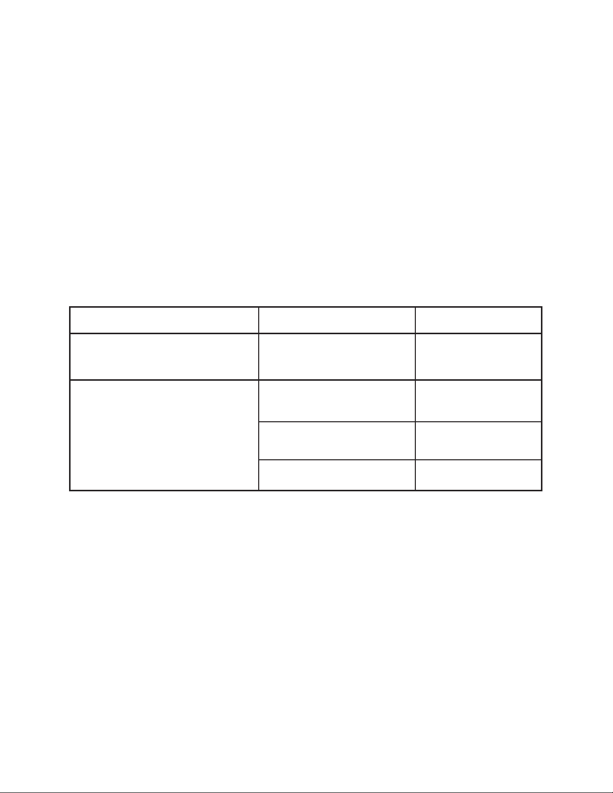
WATER SYSTEM
The water system consists of three primary elements: 1) Water Delivery System, 2) Spray Bar Assembly; 3) Pump.
Troubleshooting of this system is fairly simple.
The Water Delivery System consists of two assemblies: A) The Water Inlet assembly and B) The Plumbing assembly.
The Water Inlet assembly is made up of four components: 1) The water supply connection hose, 2) The bulkhead fit-
ting, 3) The float valve connection hose and 4) The float valve.
The Plumbing assembly consists of three elements: 1) Riser (PVC components), 2) Drain Valve, 3) Spray Bar
Adjustment Valve. The 16 inch model has no riser or valves.
The Spray Bar Assembly consists of two components: 1) Spray Bar, 2) 4 foot connection hose.
The pumps that actually move the water through the delivery system are discussed in the charts below. These charts
indicate the major symptoms of problems that may be encountered with the Water System components.
WATER INLET SYSTEM
PROBLEM CHECK SOLUTION
Floor at side of PORT-A-COOL® Water inlet hose is loose at Tighten connections
unit is wet. supply hose or inlet hose is and/or replace
loose at bulkhead fitting hose washers.
PORT-A-COOL®
sump tank or is spitting water through fan. bulkhead fitting or at float valve. /or replace hose washers.
Water pressure is too high Reduce water pressure by
to allow float valve to shutoff. checking in-line reducer.
(50 psi max.)
Float valve is not seating properly. Check for particles in
unit overflows from Float valve hose is loose at Tighten connections and
valve. Replace float valve.
*
PORT-A-COOL® Hazardous Location Units
Page 15
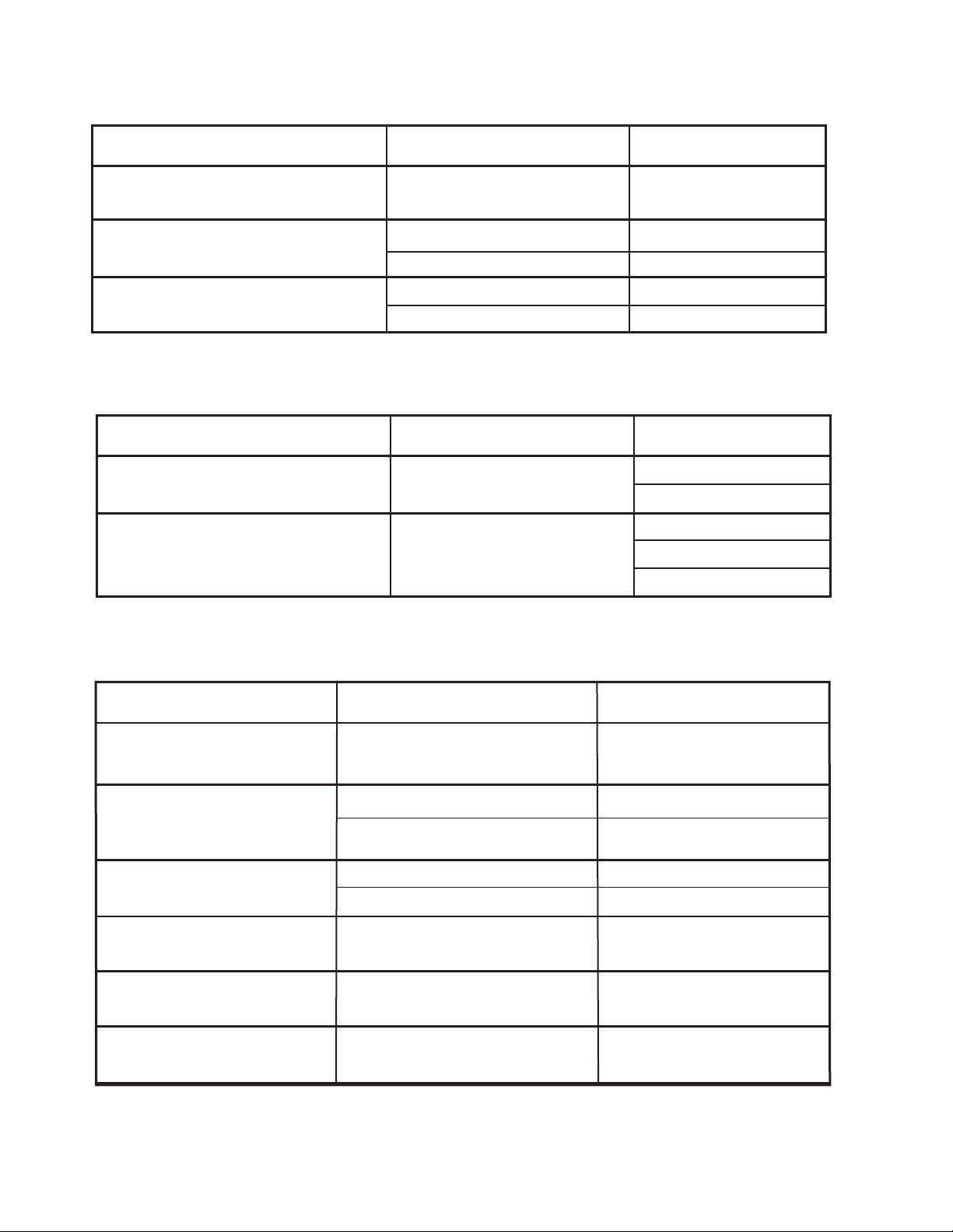
PLUMBING ASSEMBLY
PROBLEM CHECK SOLUTION
Water spitting from the from the unit. Cracked riser assembly. Replace riser assembly.
Spray Bar Adjustment valve.
Water leaking from Drain Valve. Washer worn. Replace washer.
Stem worn. Replace Drain Valve.
Water leaking from Spray Bar Valve. Washer worn. Replace washer.
Stem worn. Replace Spray Bar Valve.
SPRAY BAR ASSEMBLY (ALL MODELS)
PROBLEM CHECK SOLUTION
Too many dry streaks in the pads. Holes in spray bar blocked
by foreign material.
Water spitting from the unit. Hose connection loose. Tighten hose.
Replace hose and washer.
Reseat spray bar end caps
Clean individual holes.
Remove and clean spray bar.
BRONZE PUMP (PAC2K36EP and PAC2K48EP Only)
PROBLEM CHECK SOLUTION
Pump motor will not run when Power cord, Reconnect power,
switch is turned on. switches, circuit breaker, etc. reset breaker.
Pump motor hums when switch Object jammed into impeller blade. Remove object. Prime pump.
is turned on, but does not
pump water.
Pump makes loud noise Pump bearings. Replace pump.
while running
Breaker trips or fuse blows when Pump motor locked. Replace pump/motor.
switch is turned on.
Pump will not run and power is Switch making closure contact. Replace switch.
available and pump is functional
Pump motor running but pump Set screws on coupling. Tighten set-screw /
is not turning. Replace coupling.
Object in impeller housing.
Air Locked.
Pump/Motor locked. Replace pump/motor.
Clear object.
PORT-A-COOL® Hazardous Location Units
*
Page 16
B. Repair Procedures
Only qualified and trained distributors or factory personnel should perform repairs!!
VI. REPLACEMENT PARTS
A. Returned Merchandise Authorization (RMA) Procedures
All Port-A-Cool® units, parts, or materials being returned to Port-A-Cool, LLC for warranty replacement or
repair require an RMA (Return Merchandise Authorization) number.
There are two methods for replacing waranty parts:
1. The distributor can purchase the part with an RMA number and will only be charged for
the cost of the part, not for the shipping. When the defective part is returned, the
distributor’s account will be credited for the cost of the part.
2. The customer / distributor can call Tech Support to get an RMA number to send the
defective part back to Port-A-Cool, LLC. Once the part is received by Port-A-Cool, LLC, a
replacement part will be sent at no charge.
Information needed to get an RMA number:
1. The UNIT serial number.
2. The UNIT model number (ex. PAC2K363S)
3. The part number or description of the part to be replaced.
Only major component parts need an RMA number, i.e. fans, motors, pumps, and some plumbing parts.
For replacement of small parts, the serial and model numbers are still required, but the parts do not need ot be
returned to Port-A-Cool, LLC.
For warranty replacement parts call PORT-A-COOL® Technical Support at 1-888-266-5243.
FAX: 936-598-1431 or [email protected].
Shipping Address Mailing Address:
Port-A-Cool, LLC Port-A-Cool, LLC
721 FM 2468 P.O. Box 2167
Center, Texas 75935 Center, Texas 75935
B. Port-A-Cool® Unit Limited Warranty
For one year from date of installation, Port-A-Cool, LLC, warrants any original component part or parts
of the Port-A-Cool® evaporative unit found, upon examination by factory authorized personnel, to be defective
in material or workmanship. All transportation charges on parts submitted for replacement or repair under this
warranty must be borne by the purchaser. If said equipment develops such defects within this period, it will be
repaired or replaced at our option. For breach of any implied or written warranty on this product, Port-A-Cool,
LLC, shall not be liable for any incidental or consequential damages. This warranty is declared void if the equipment if found to have been misused, abused or tampered with by unauthorized personnel.
Due to warranty limits placed on our products by the original manufacturers, our warranty is limited on
manufactured units and their original component parts as well as replacement parts to a total of one (1) year
after the date of installation.
*
PORT-A-COOL® Hazardous Location Units
Page 17
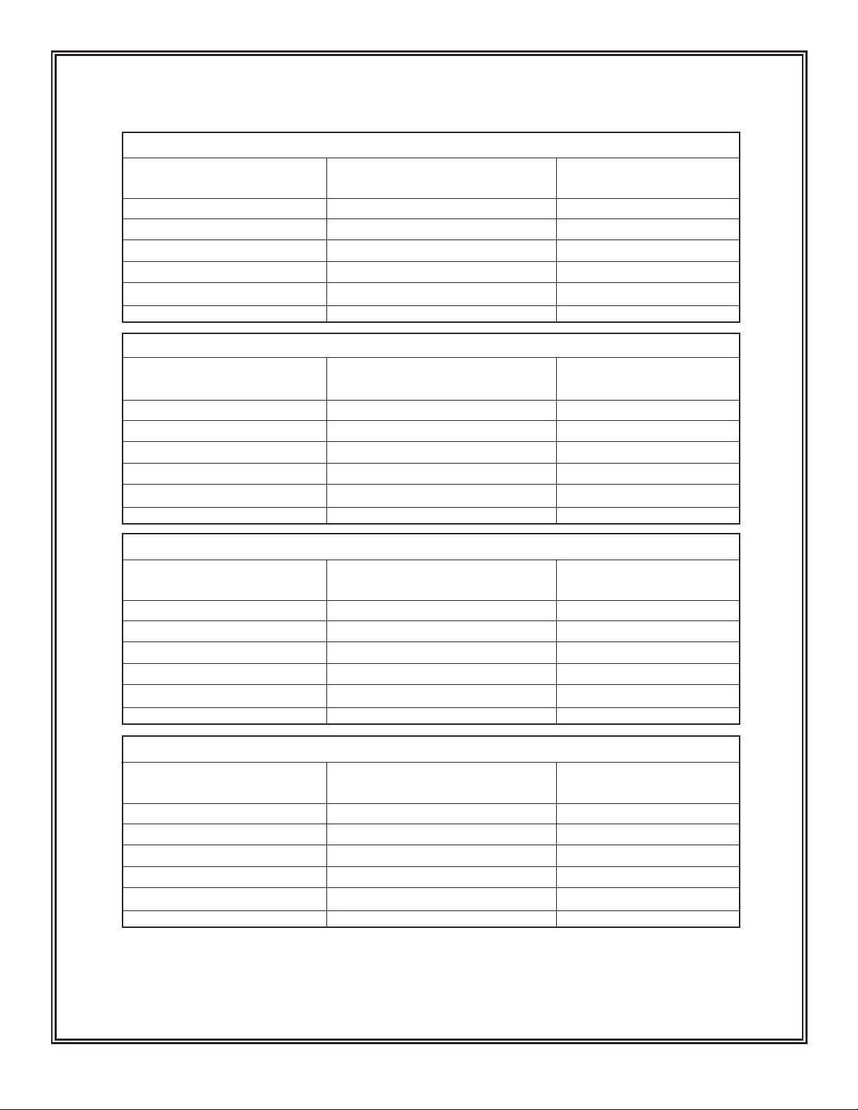
APPENDIX A
10% RH
Temp. °C Temp. °F
15% RH
Temp. °C Temp. °F
TEMPERATURE OUTPUT CHARACTERISTICS
DRY BULB
32.2 90
35.0 95
37.8 100
40.6 105
43.3 110
46.1 115
DRY BULB
32.2 90
35.0 95
37.8 100
40.6 105
43.3 110
46.1 115
Port-A-Cool®
10% TO 25% RELATIVE HUMIDITY
TEMP. °F
Difference Drop
65 46.8
65 46.8
66 47.5
67 48.2
68 49.0
67 48.2
TEMP. °F
Difference Drop
55 39.6
56 40.3
57 41.0
57 41.0
58 41.8
59 42.5
OUTPUT TEMP.
°C
6.1 43
8.9 48
11.1 52
13.9 57
16.1
19.4 67
61
OUTPUT TEMP.
°C
10.0 50
12.8 55
15.0 59
17.8 64
20.0
22.8 73
68
°F
°F
20% RH
DRY BULB
Temp. °C Temp. °F
32.2 90
35.0 95
37.8 100
40.6 105
43.3 110
46.1 115
Difference Drop
25% RH
DRY BULB
Temp. °C Temp. °F
32.2 90
35.0 95
37.8 100
40.6 105
43.3 110
46.1 115
WET BULB TEMPERATURE
DRY BULB TEMPERATURE
TEMPERATURE DIFFERENCE
TEMPERATURE DROP
OUTPUT TEMPERATURE
Difference Drop
TEMP. °F
47 33.8
47 33.8
48 34.6
49 35.3
49 35.3
51 36.7
TEMP. °F
41 29.5
43 31.0
44 31.7
44 31.7
44 31.7
45 32.4
Wet Bulb Temperature @ Current Humidity Level
Current Ambient Air Temperature
Dry Bulb Temp Minus Wet Bulb Temp
Temperature Difference Multiplied by 72%
Dry Bulb Temperature Minus Temperature Drop
OUTPUT TEMP.
°C
13.3 56
16.1 61
18.3 65
21.1 70
23.9
25.6 78
75
OUTPUT TEMP.
°C
15.6 60
17.8 64
20.0 68
22.8 73
25.6
28.3 83
78
°F
°F
A-1
*
PORT-A-COOL® Hazardous Location Units
Page 18
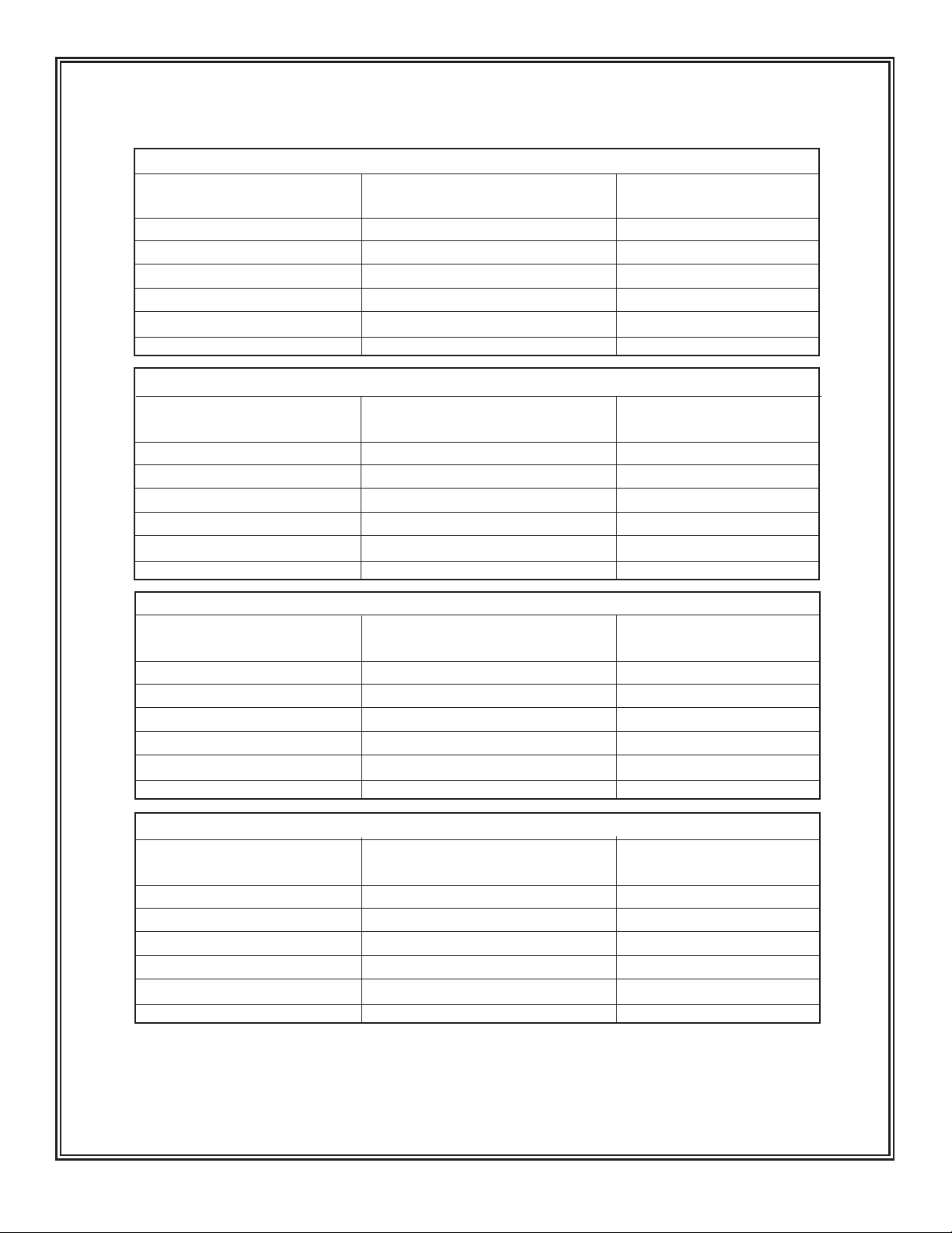
APPENDIX A
30% RH
Temp. °C Temp. °F
35% RH
Temp. °C Temp. °F
TEMPERATURE OUTPUT CHARACTERISTICS
DRY BULB
26.7 80
29.4 85
32.2 90
35.0 95
37.8 100
40.6 105
DRY BULB
23.9 75
26.7 80
29.4 85
32.2 90
35.0 95
37.8 100
Port-A-Cool®
30% TO 45% RELATIVE HUMIDITY
TEMP. °F
Difference Drop
34 24.5
35 25.2
35 25.2
36 25.9
37 26.6
38 27.4
TEMP. °F
Difference Drop
30 21.6
31 22.3
30 21.6
32 23.0
32 23.0
33 23.8
OUTPUT TEMP.
°C
13.3 56
15.6 60
18.3 65
20.6 69
22.8
25.6 78
73
OUTPUT TEMP.
°C
11.7 53
14.4 58
17.2 63
19.4 67
22.2
24.4 76
72
°F
°F
40% RH
DRY BULB
Temp. °C Temp. °F
29.4 85
32.2 90
35.0 95
37.8 100
40.6 105
43.3 110
Difference Drop
45% RH
DRY BULB
Temp. °C Temp. °F
29.4 85
32.2 90
35.0 95
37.8 100
40.6 105
43.3 110
WET BULB TEMPERATURE
DRY BULB TEMPERATURE
TEMPERATURE DIFFERENCE
TEMPERATURE DROP
OUTPUT TEMPERATURE
Difference Drop
TEMP. °F
27 19.4
28 20.2
29 20.9
27 19.4
29 20.9
28 20.2
TEMP. °F
24 17.3
25 18.0
25 18.0
25 18.0
25 18.0
25 18.0
Wet Bulb Temperature @ Current Humidity Level
Current Ambient Air Temperature
Dry Bulb Temp Minus Wet Bulb Temp
Temperature Difference Multiplied by 72%
Dry Bulb Temperature Minus Temperature Drop
OUTPUT TEMP.
°C
18.9 66
21.1 70
23.3 74
27.2 81
28.9
32.2 90
84
OUTPUT TEMP.
°C
20.0 68
22.2 72
25.0 77
27.8 82
30.6
33.3 92
87
°F
°F
A-2
PORT-A-COOL® Hazardous Location Units
*
Page 19
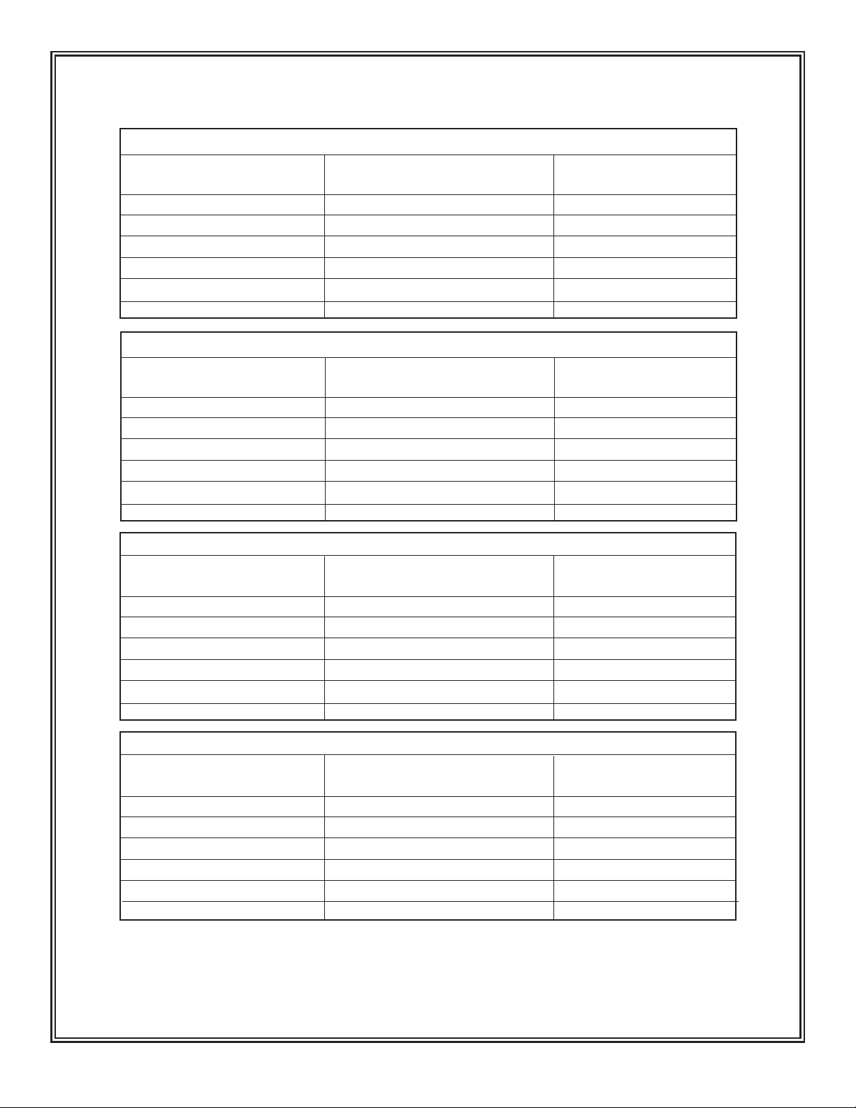
APPENDIX A
50% RH
Temp. °C Temp. °F
55% RH
Temp. °C Temp. °F
TEMPERATURE OUTPUT CHARACTERISTICS
DRY BULB
23.9 75
26.7 80
29.4 85
32.2 90
35.0 95
37.8 100
DRY BULB
23.9 75
26.7 80
29.4 85
32.2 90
35.0 95
37.8 100
Port-A-Cool®
50% TO 65% RELATIVE HUMIDITY
TEMP. °F
Difference Drop
22 15.8
20 14.4
22 15.8
21 15.1
22 15.8
22 15.8
TEMP. °F
Difference Drop
17 12.2
19 13.7
18 13.0
19 13.7
19 13.7
19 13.7
OUTPUT TEMP.
°C
15.0 59
18.9 66
20.6 69
23.9 75
26.1
28.9 84
79
OUTPUT TEMP.
°C
17.2 63
18.9 66
22.2 72
24.4 76
27.2
30.0 86
81
°F
°F
60% RH
DRY BULB
Temp. °C Temp. °F
23.9 75
26.7 80
29.4 85
32.2 90
35.0 95
37.8 100
Difference Drop
65% RH
DRY BULB
Temp. °C Temp. °F
23.9 75
26.7 80
29.4 85
32.2 90
35.0 95
37.8 100
WET BULB TEMPERATURE
DRY BULB TEMPERATURE
TEMPERATURE DIFFERENCE
TEMPERATURE DROP
OUTPUT TEMPERATURE
Difference Drop
TEMP. °F
15 10.8
15 10.8
15 10.8
15 10.8
17 12.2
16 11.5
TEMP. °F
13 9.4
13 9.4
13 9.4
13 9.4
14 10.1
13 9.4
Wet Bulb Temperature @ Current Humidity Level
Current Ambient Air Temperature
Dry Bulb Temp Minus Wet Bulb Temp
Temperature Difference Multiplied by 72%
Dry Bulb Temperature Minus Temperature Drop
OUTPUT TEMP.
°C
17.8 64
20.6 69
23.3 74
26.1 79
28.3
31.1 88
83
OUTPUT TEMP.
°C
18.9 66
21.7 71
24.4 76
27.2 81
29.4
32.8 91
85
°F
°F
A-3
*
PORT-A-COOL® Hazardous Location Units
Page 20
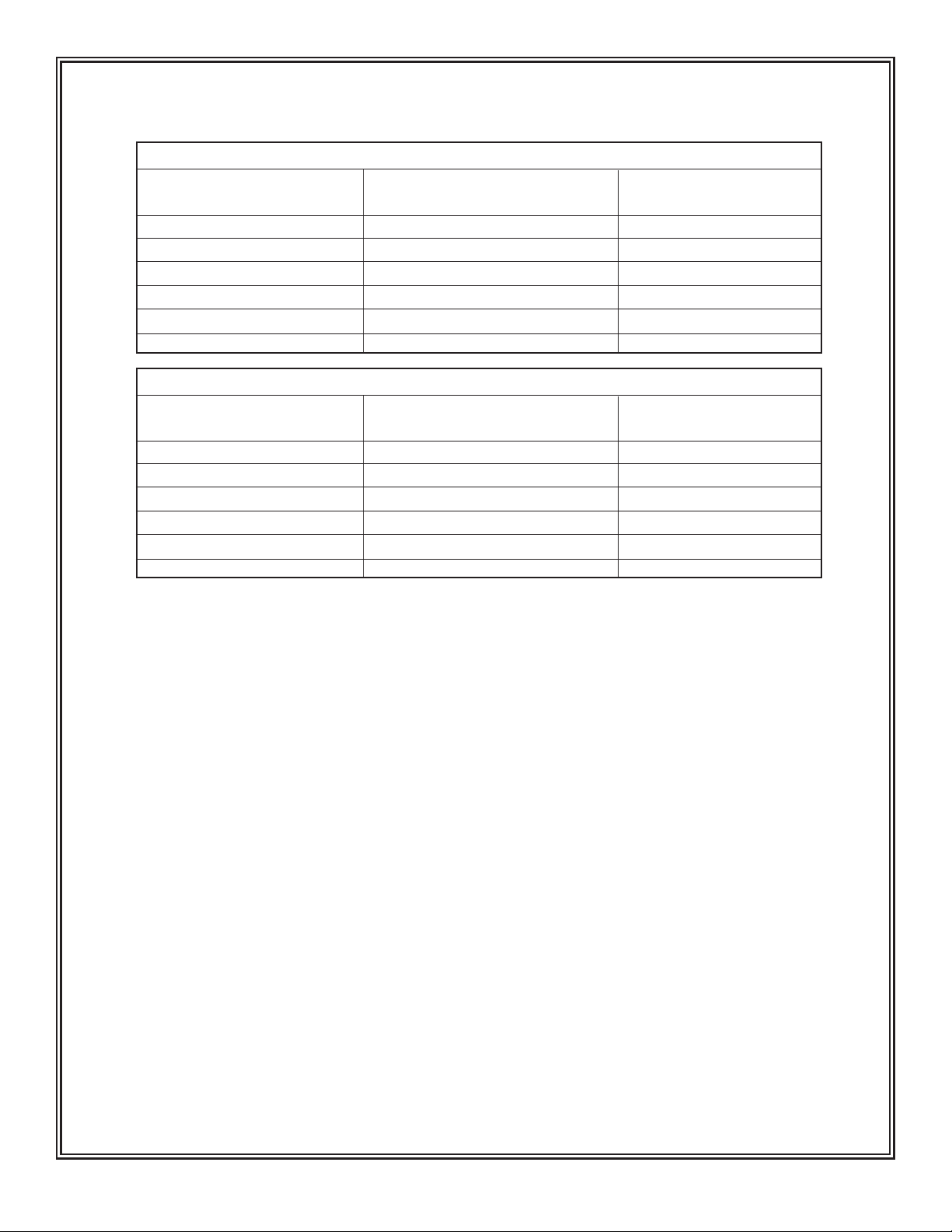
APPENDIX A
70% RH
Temp. °C Temp. °F
75% RH
Temp. °C Temp. °F
TEMPERATURE OUTPUT CHARACTERISTICS
DRY BULB
21.1 70
23.9 75
26.7 80
29.4 85
32.2 90
35.0 95
DRY BULB
18.3 65
21.1 70
23.9 75
26.7 80
29.4 85
32.2 90
Port-A-Cool®
70% TO 75% RELATIVE HUMIDITY
TEMP. °F
Difference Drop
10 7.2
10 7.2
11 7.9
11 7.9
12 8.6
12 8.6
TEMP. °F
Difference Drop
8 5.8
8 5.8
9 6.5
9 6.5
9 6.5
9 6.5
OUTPUT TEMP.
°C
17.2 63
20.0 68
22.2 72
25.0 77
27.2
30.0 86
81
OUTPUT TEMP.
°C
15.0 59
17.8 64
20.6 69
23.3 74
26.1
28.9 84
79
°F
°F
WET BULB TEMPERATURE
DRY BULB TEMPERATURE
TEMPERATURE DIFFERENCE
TEMPERATURE DROP
OUTPUT TEMPERATURE
PORT-A-COOL® Hazardous Location Units
Wet Bulb Temperature @ Current Humidity Level
Current Ambient Air Temperature
Dry Bulb Temp Minus Wet Bulb Temp
Temperature Difference Multiplied by 72%
Dry Bulb Temperature Minus Temperature Drop
A-4
*
 Loading...