


MODEL
WS-10-64-3
WELD SHEAR
1805 2ndAVENUE NORTH * MOORHEAD, MN, USA 56560-2310
E-MAIL ADDRESS; info@portaco.com * INTERNET ADDRESS: www.portaco.com
OPERATION,
MAINTENANCE,
AND REPAIR
MANUAL
PHONE (218) 236-0223 * FAX (218) 233-5281
1

TABLE OF CONTENTS
1.0 Introduction
1.1 General Information
1.2 Features
1.3 Safety Summary
1.4 General Safety Precautions
1.5 Warning and Caution Statements
1.6 Training Requirements
2.0 Installation Instructions
2.1 Unpacking Instructions
2.2 Tool Preparations
2.3 Testing
2.4 Hose Requirements
2.5 Hydraulic Fluid Recommendations
2.6 Tool Connecting Procedures
2.7 Work Area Safety Precautions
3.0 Operating Instructions
3.1 Description of Power Unit
3.2 Controls and Graphics
3.3 Before Operating
3.4 Positioning on Rail
3.5 Connecting Hoses
3.6 Operating Instructions
3.7 Disconnecting Hoses
3.8 Cold Weather Operation
3.9 Storage Preparation
4.0 Maintenance Instructions
4.1 Assembly View and Parts List
4.2 Graphic Set Complete
4.3 Tool Maintenance
4.4 Trouble Shooting
4.5 Technical Specification
2
1.0 INTRODUCTION
C
1.1 General Information
This manual presents removal,
operation, and maintenance
information for PortaCo’s model
WS-10-64-3 Weld Shear. The tool is
designed to remove the excess
material when performing Thermit
and Buta type welds. It's light weight
compact size allows for use inside
rail pulling equipment. All hydraulic
plumbing is protected by a one piece
guard to prevent damage and to
contain any leaks if any damage
occurs. When properly used this tool
will help reduce back strain and also
reduce operator fatigue.
shearing blades to the full open
position when the valve control lever
is released. (See figure 1.2A arrow
A) This reduces total shearing time
and reduces the operator's exposure
to the heat produced during the
welding procedure.
B
A
Figure 1.2A
PortaCo, Inc. reserves the right to
make changes at anytime without
notice and without incurring any
obligation.
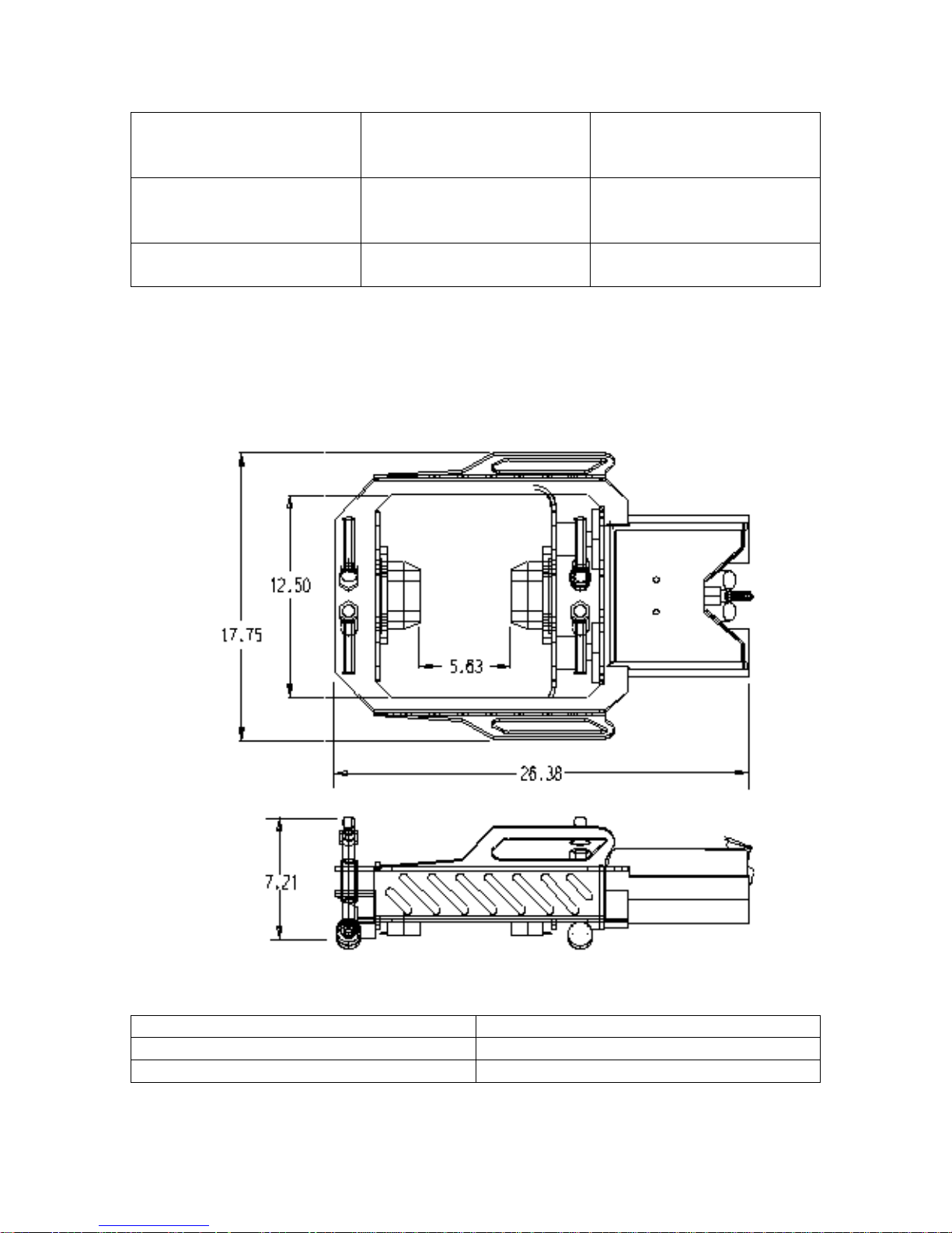
1.2 Features
The main features of the PortaCo
Weld Shear Model WS-00-64-3 are
as follows.
Standard unit:
Length 26.38 in/ 67.0 cm
Width 17.75 in/ 45.1 cm
Height 7.21 in/ 18.3 cm
Weight 84-lbs/ 38.1 kg
(includes blades)
Upper ambient operating
temperature 110°F (43° C), lower
ambient operating temperature -20°F
(-28° C).
PortaCo, Inc.'s weld shear features
an auto cycle valve which returns the
The control valve also limits the
speed for shearing and provides a
rapid retract for easy operation.
The hydraulic plumbing is protected
by a one-piece guard to prevent
damage and to contain any leaks if
any damage occures. (figure 1.2A
arrow B)
The hydraulic quick connect couplers
are located at the rear of the shear
and directs the hoses along the rail
out of the work area. (figure 1.2A
arrow C) The path of the hose's
along the rail reduces the potential
for a worker to trip on them.
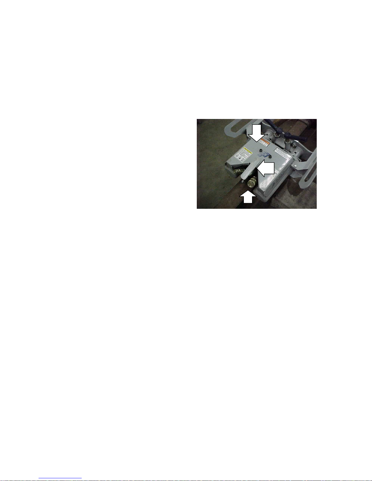
Roller hold-downs, provide a secure
mount to the rail and allows smooth
operation during the shearing
process. The roller height is set with
a jam nut providing a snug fit on any
size rail. (figure 1.2B arrow A)
3
The roller assembly is easily
A
B
removed for replacement of any
component of the hold-down
assembly. (figure 1.2B arrow B)
Figure 1.2B
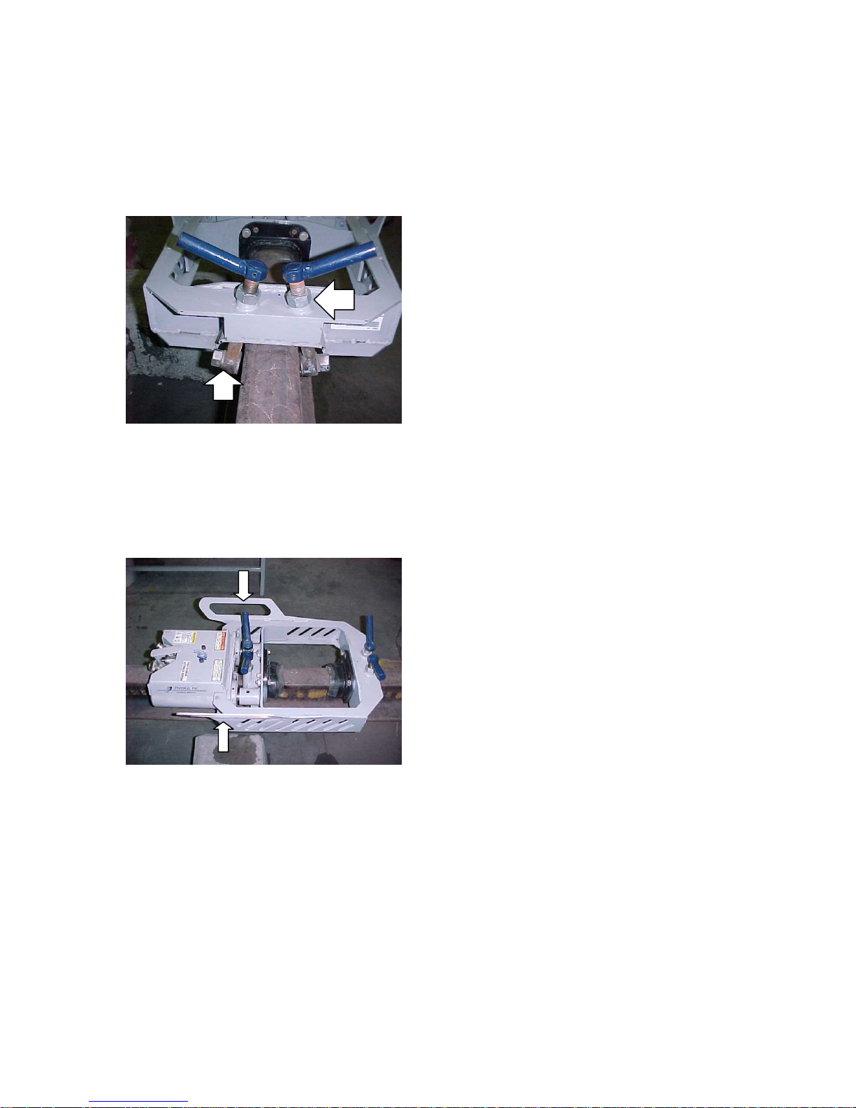
Handles incorporated into the frame
allow for even balance and level
transportation for quick positioning
on the rail. Figure 1.3
and before performing maintenance
or repairs. Supervising personnel
should develop additional
precautions relating to the specific
work area and local safety
regulations.
1.4 General Safety Precautions
The PortaCo Inc. tools are designed
to provide safe and dependable
service if operated according to the
instructions provided in this manual.
Read and understand this manual
and any stickers attached to the
power unit before operating. Failure
to do so could result in personal
injury or equipment damage.
Check the rules and regulations at
your location. The rules may include
an employer’s work safety program.
Regulations may identify hazards
such as working around utility supply
lines or hazardous slopes.
1.3 Safety Summary
Tool operators and maintenance
personnel must always comply with
the safety precautions given in this
manual and on the stickers and tags
attached to the tool and hoses.
These safety precautions are given
for your safety. Review them
carefully before operating the tool
Read and understand any manuals
for additional or optional equipment,
which maybe shipped with the tool.
1.5 Warning and Caution
Statements
Warning and Caution statements
have been strategically placed
throughout the text prior to operating
or maintenance procedures,
practices, or conditions considered
essential for the protection of
personnel, equipment, and property.
WARNING: HIGHLIGHTS A,
ESSENTIAL OPERATING, OR
MAINTENANCE PROCEDURE,
PRACTICE, CONDITION
STATEMENT, ETC… WHICH IF
NOT STRICTLY OBSERVED,
4

COULD RESULT IN INJURY TO,
OR DEATH OF, PERSONNEL OR
LONG TERM HEALTH HAZARDS.
CAUTION: HIGHLIGHTS AN
ESSENTIAL OPERATING OR
MAINTENANCE PROCEDURE,
PRACTICE, CONDITION
STATEMENT, ETC. WHICH IF NOT
STRICTLY OBSERVED, COULD
RESULT IN DAMAGE TO, OR
DESTRUCTION OF, EQUIPMENT
OR LOSS OF MISSION
EFFECTIVENESS.
1.6 Training Requirements
Operator training for the weld shear
should consist of information found
in this manual. In addition the
operator must receive instructions,
both verbally and through
demonstrations for applications in
which the tool is going to be used.
The new operator must start in an
area without bystanders and use the
tool until able to fully operate the tool
under the conditions for the work
area.
2.0 INSTALLATION INSTRUCTIONS
2.1 Unpacking Instructions
Upon receiving your weld shear
promptly remove it from the shipping
container. Always keep top side of
container up. Inspect unit for
damage which may have incurred
during shipping and report it to
carrier for claim.
2.2 Tool Preparations
The PortaCo G-18D55-53-W power
unit is recommended for hydraulic
supply. This unit is equipped with
two 5-gpm/20 lpm circuits that can
be combined for on 10 gpm/40 lpm
circuits.
If the tool is used in cold weather,
preheat the hydraulic fluid by running
power source at low engine speed.
Fluid temperature should be at or
above 50° F/10° C (400-ssu/82
centistroke) before use, when using
recommended fluids. Using too thick
of fluid may result in tool damage.
2.3 Testing
WARNING: NEVER STICK
FOREIGN OBJECTS, FINGERS,
OR OTHER EXTRMITIES INTO
MOVING MECHANISMS. FAILURE
TO FOLLOW THESE
INSTRUCTIONS MAY LEAD TO
SEVERE PERSONAL INJURY OR
TOOL DAMAGE.
Before operating the weld shear it is
important to inspect the shear blades
for excessive wear or damage.
Replace the shear blades if required
before operating the shear. Follow all
safety precautions and procedures
when inspecting tool.
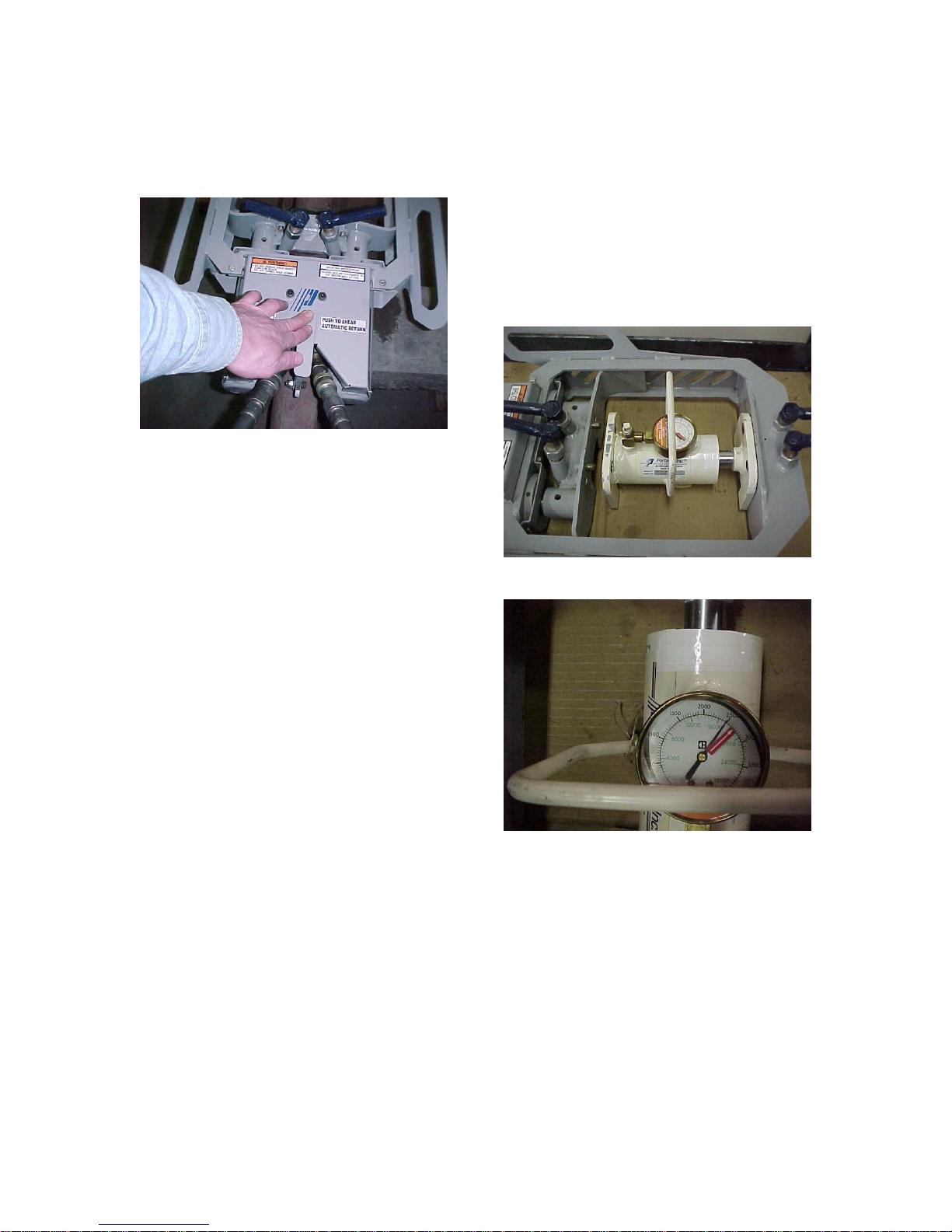
To test the function of the shear,
connect the hydraulic hoses to the
tool see section 2.6 of this manual
for proper procedure. With the flow
from the power source "on" press the
control lever down and hold it there.
(See figure 2.3A) The shear blades
should close at a slow rate of speed.
Allow the blades to contact each
other. Release the lever and the
shear blades should move to full
open without touching the lever or
any form of assistance.
5
If the shear fails to complete any of
these functions see the trouble
shooting section of this manual.
Figure 2.3A
CAUTION: THE PRESSURE
TESTING PROCEDURE MUST BE
CONDUCTED BY A QUALIFIED
HYDRAULIC TECHNICIAN.
To test the pressure exerted at the
shear blades, disconnect the shear
from the power source. Remove the
shear blades from the frame.
The needle should be within 500 psi
of the red arrow. (figure 2.3C) When
testing follow the instructions
provided with the test equipment.
Testers other than PortaCo. Inc.'s
model TS-00-XX-O may instruct the
technician to perform the test in a
manor slightly different than the
procedure just described.
Figure 2.3B
Insert a pressure testing system
between the frame and the ram end
frame of the shear. PortaCo's Model
TS-00-X-O Tester Shear, is
recommended for this procedure.
(see figure 2.3B)
The model TS-00-X-O tester is
capable of testing most shears. It
features a pressure gauge with and
arrow indicating the optimum force
applied.
Position tester while closing the
shearing mechanism, aligning the
pins in the frames with the holes in
the tester. Hold the control lever
down till the needle, on the pressure
gauge, of the tester stops climbing.
Figure 2.3C
CAUTION: WHEN TESTING THE
RAIL SHEAR, BE SURE TO
FOLLOW ALL SAFETY
GUIDELINES.
2.4 Hose Requirements
It is not often necessary or advisable
to use long hoses. All hoses must
have an oil resistant inner surface
and an abrasion resistant outer
6

surface. Each hose must have male
FLOW PER CIRCUIT
SAE SPEC HOSE
pipe ends for most application.
Longer hoses can be used when
necessary, but can affect the
operation of the engine due to
resistance in the hose.
If small diameter or long hoses are
used, or if restrictive fittings are
connected to the supply and return
ports, the pressure required to push
the fluid through the system and
back to the tank will be higher. This
will reduce tool power.
HOSE TYPES
Hydraulic hose types authorized for
use by PortaCo, Inc. is as follows:
1. Labeled and certified nonconductive
2. Wire braided (conductive)
3. Fabric braided (not certified or
labeled non-conductive)
Hose 1: Listed above is the only
hose authorized for use near
electrical conductors.
*Important – Oil should always
flow from the male coupler
through the female coupler.
NOTE: The pressure increase in
uncoupled hoses left in the sun may
make them difficult to connect.
When possible after use, connect the
free ends of the operating hoses
Hoses 2 and 3: Listed above are
conductive and must never be used
near electrical conductors.
HOSE PRESSURE RATING
The rated working pressure of the
hydraulic hose must be at least 175
bar (2500 psi).
together.
HYDRAULIC HOSE RECOMMENDATION
Table 2.4
LENGTH EACH HOSE USE INSIDE DIAMETER
GPM LPM FEET METERS INCH MM
5 to 8 19 to 30 To 50 To 15 Both ½ 13 SAE 100R1-8 100R7-8
5 to 8 19 to 30 51-100 15 to 30 Both 5/8 16 SAE 100R2-10 SAE 100R8-10
5 to 8 19 to 30 100-300 30 to 90 Pressure
Return
9 to 12 34 to 45 To 50 To 15 Both 5/8 16 SAE 100R2-10 SAE 100R8-10
9 to 12 34 to 45 51-100 15 to 30 Pressure
Return
9 to 12 24 to 45 100-200 30 to 60 Pressure
Return¾1
5/8
¾
5/8
¾
16
19
16
19
19
25.4
(WIRE DRAID)
SAE 100R2-10
SAE 100R1-12
SAE 100R2-10
SAE 100R3-12
SAE 100R2-12
SAE 100R1-16
SAE SPEC
HOSE (FIBER
BRAID)
SAE 100R8-10
SAE 100R7-12
SAE 100R8-10
SAE 100R7-12
SAE 100R8-12
SAE 100R7-16
2.5 Hydraulic Fluid Recommendation
Inspect hose for cuts, crushing, leaks,
or abrasion which maybe a safety
hazard or reduce fluid flows.
The following fluids work well over a
Wide temperature range at startup,
Allow moisture to settle out, and resist
Biological growth likely in cool operating
Hydraulic circuits. These fluids are
Recommended by PortaCo inc. Other
That meets or exceeds the specifications
of these fluids may also be used.
7

Type Hydraulic fluid
Chevron “Clarity” AW 15032
Exxon “Univis” J 32
Mobil D.T.E. 13 M
Gulf “Harmony” AW-HVI-150-32
Shell “Tellus T” 32
Texaco “Rando” HDZ 32
Union “Unax” AW-WR-32
Amsoil AWH 15032
Sunvis
Low Pour H/032-product code 19300
Hydraulic fluid requirements:
WARNING: PRESSURIZED FLUID
ESCAPING FROM A DAMAGED
HOSE CAN PENETRATE THE
SKIN AND BE INJECTED IN THE
BODY CAUSING INJURY OR
DEATH.
CAUTION: DO NOT PULL ON
HOSES TO DRAG POWER UNIT.
a) Viscosity (fluid Thickness)
USA METRIC
50 F 4450 SSU Max 10 C 95 Centistokes
100 F 130-200 SSU 38 C 27-42 C.S.
140 F 85 SSU Min. 60 C 16.5 C.S, Min.
Pour Point- 10 F/-23 C Minimum (for cold startup)
Viscosity Index (ASTM D 2220) 140Minimum
Demulsibility(ASTM D-1401) 30 Minutes
Maximum
Flash Point (ASTM D-92) 340 F/171 C Minimum
Rust Inhibition (ASTM D-665 A & B) Pass
Oxidation(ASTM D943) 1000 Hours Minimum
Pump Wear Test (ASTM D2882) 60 mg
Maximum
2.6 Tool Connecting Procedures
Stop the engine before connecting
the tool and, or hoses to the power
unit, and when switching hoses or
tools. Turn the hydraulic on/off valve
to the off position before starting the
engine. Make sure all hose are
connected for correct flow direction
to and from the tool being used.
When routing hose in the work area,
position them where personnel will
not be at risk of tripping over them or
where vehicles can run over the
hoses. Do not lay hose over sharp
objects.
2.7 Work Area Safety Precautions
- Never operate the tool when you
are tired, angry, emotionally
disturbed, or under the influence
of alcohol, drugs, medications, or
anything that could affect your
vision, alertness, coordination or
judgement.
- Establish a training program for all
operators to ensure safe
operation.
- Do no operate the tool unless
thoroughly trained or under the
supervision of an instructor.
- Do not allow others to be near the
tool when starting it or while
operating. Keep bystanders and
animals out of the work area.
- Always wear safety goggles, ear,
leg, and head protection devices,
safety footwear, and snug fitting
clothes.
- Do not operate the tool near
energized transmission lines.
- Do not overreach. Maintain
proper footing and balance at all
times.
8

- Be sure to keep hands and other
parts clear and free from all
moving parts.
- Keep all body parts away from
moving jaws.
- Always connect hydraulic hoses to
the tool before activating the
hydraulic circuit on your power
unit. Check that hydraulic
couplers are secure before
activating the circuit.
- Only a properly trained person
should perform any maintenance,
service, and or repairs to a tool.
- Never operate a tool that is
damaged, improperly adjusted, or
not completely and securely
assembled.
- Do not operate the tool until you
have a clear work area and a
secure balance.
- Keep handles clean and dry.
- Never carry or pick this tool up by
the hydraulic hose
- Disconnect tool from hydraulic
source before inspection or
cleaning.
SAFETY REGULATION
Enter below any local or other safety regulations required for the operator to
follow. Make sure the operator and maintenance personnel have knowledge of
these regulations.
________________________________________________________________
________________________________________________________________
________________________________________________________________
________________________________________________________________
________________________________________________________________
________________________________________________________________
________________________________________________________________
________________________________________________________________
________________________________________________________________
________________________________________________________________
________________________________________________________________
________________________________________________________________
________________________________________________________________
________________________________________________________________
9

3.0 Operating Instructions
3.1 Description of Power Tool
PortaCo’s model WS-10-64-3 Weld
Shear is intended to be used to
shear Thermit and Buta type welds.
It's light-weight construction and
auto cycle valve reduces operator
fatigue.
PSI). The maximum pressure of the
hydraulic system is limited to 148.3
BAR (2150 PSI). The power source
provided the required flow and
pressure to operated HTMA type I
15-23 LPM (4-6 GPM) and type RR
34-40 LPM (9-10.5) tools. All which,
are OPEN-CENTER tools required
an operating pressure of 138 BAR
(2000 PSI).
The closing rate of the shear
blades, are limited to the industries
standard and cannot be altered.
When the control lever is release
the blades automatically retract at a
more rapid rate to reduce shearing
time.
The PortaCo Weld Shear secures to
the rail at four points. Adjustable
roller hold downs provide a smooth
shearing operation and guide the
shear on worn rail. Hold down
assemblies have been designed to
be easily serviced in the field.
Hydraulic quick connect couplers
are located at the rear of the tool to
allow more convenient routing of the
supply hoses.
Fully guarded hydraulic plumbing
protects the operator from
accidental leakage of oil onto the
welded area, reducing the potential
for a fire.
The G-18D55-53-W is a versatile
power unit that can meet the needs
for most hydraulic tools used by the
rail road industry. This power unit is
capable of powering two tools
simultaneously at 5 GPM (20 LPM)
or one tool a 10 GPM (40 LPM) all
the flows are at 138 BAR (2000
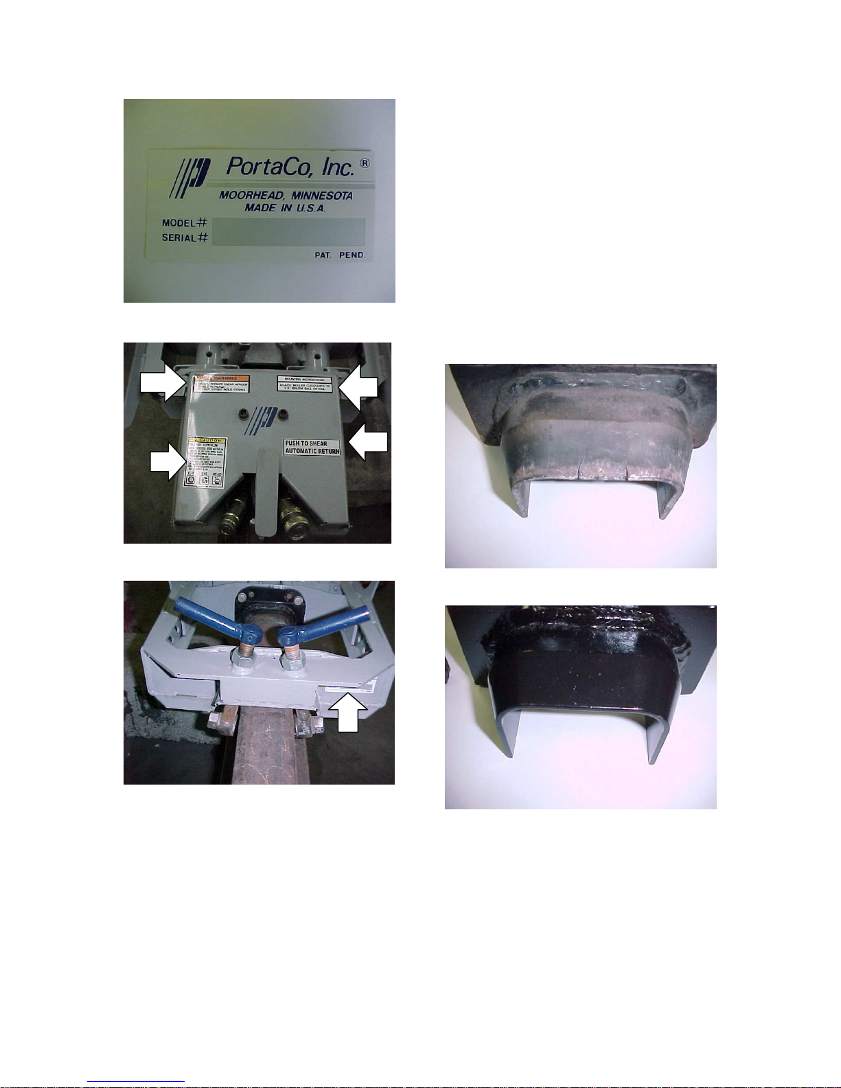
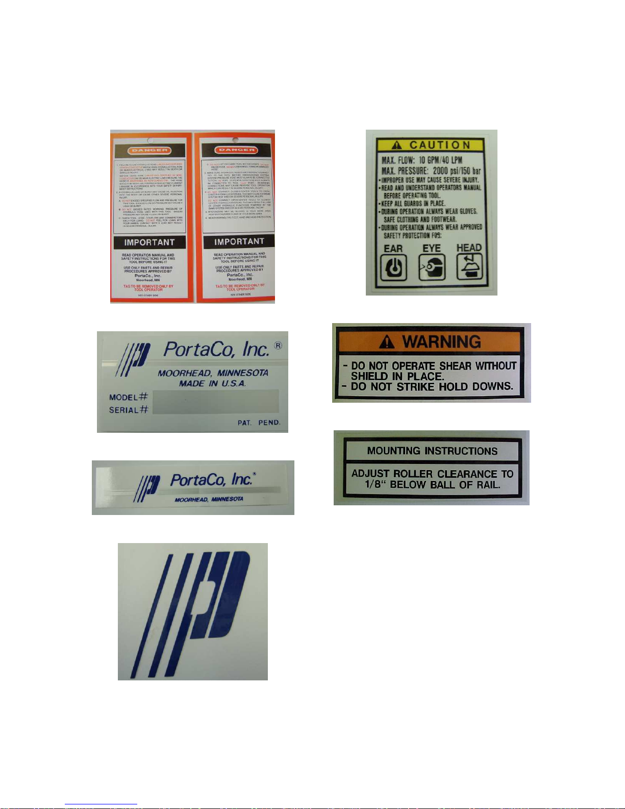
3.2 Controls and Graphics
The following decals are placed on
the tool to aid in its operation and
maintenance. The operator should
locate and understand them before
using this power tool.
The weld shear has five instructional
decals located on the tool.
On the hydraulic system guard cover
there is a CAUTION decal that
specifies that the weld shear is rated
for a flow of 10 GPM/40 LPM and
pressure of 2000 PSI/150 BAR do
not exceed these flow / pressure
ratings. Also on the decal is a few
written warnings “improper use may
cause severe injury, read and
understand operators manual before
operating tool, keep all guards in
place, during operation always wear
gloves, safe clothing and footwear,
and during operation always wear
approved safety protection for ears,
eyes, and head.” (figure 3.2A) (figure
3.2F arrow A)
10
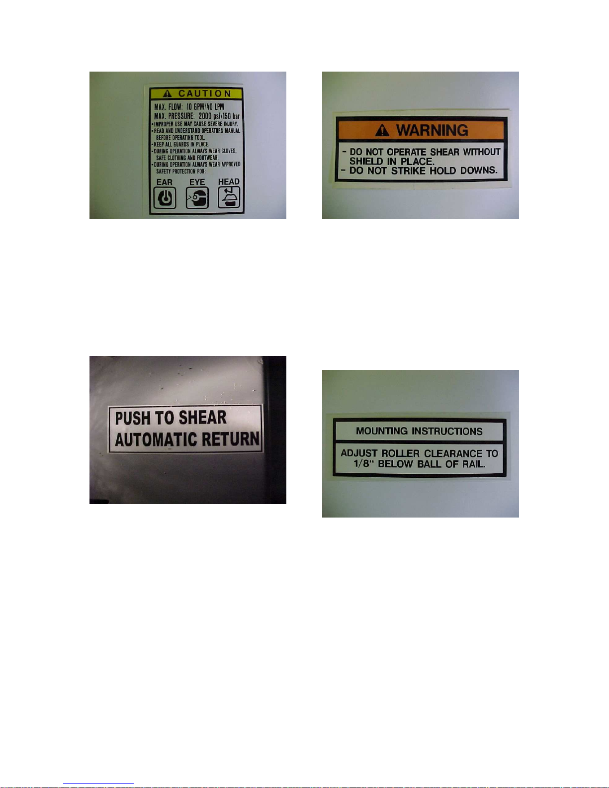
Figure 3.2A
Figure 3.2C
The valve lever operating instruction
decal is located to the right of the
control and instructs the operator to
"PUSH TO SHEAR, AUTOMATIC
RETURN".(figure 3.2B)(figure 3.2F
arrow B)
Figure 3.2B
The "WARNING' decal indicates a
practice which if conducted could
result in injury to the operator or
bystander, or damage to the tool.
Follow the instructions "DO NOT
OPERATE SHEAR WITHOUT
SHIELD IN PLACE" and "DO NOT
STRIKE HOLD DOWNS" printed on
this decal. (figure 3.2C) (figure 3.2F
arrow C).
The mounting instructions decal is
also located on the guard cover. It
states the correct procedure for
adjusting the hold down rollers.
It tells the operator to "ADJUST
ROLLER CLEARANCE TO 1/8"
BELOW BALL OF RAIL". (figure
3.2D)(figure 3.2F arrow D)
Figure 3.2D
On the inside of the far side of the
frame, is a serial # decal. This decal
has the serial number as well as the
model number of the unit. Each unit
has it’s own unique serial number. It
is important to keep this decal
protected and kept legible. The
serial number is needed when
ordering replacement parts.
(figure 3.2E)(figure 3.2G arrow E)
11
ABC
D
a leak is present, hydraulic oil on the
weld area is flammable.
Inspect the hold down assemblies,
make sure they all operate properly.
Replace any damaged or severely
worn components before operation.
Hold downs which aren't operating
correctly may result in an inferior
sheared weld.
Figure 3.2E
Figure 3.2F
Inspect the shear blades and replace
if severely worn or damaged.
BAD "REPLACE"
Figure 3.2G
3.3 Before Operating
Check that the guard is in position
and securely fastened, and in good
condition. Inspect the weld shear for
any hydraulic oil leaks and repair as
required, Do Not operate the shear if
E
GOOD
Inspect hoses, which connect weld
shear to power source for wear,
cracking, fatigue, or leaks before
using. Also check that couplers are
in good condition.
12
WARNING: NEVER INSPECT
PRESSURIZED HOSES,
COUPLERS, OR FITTINGS WITH
HANDS OR AT CLOSE
DISTANCES. PRESSURIZED
FLUID CAN PUNCTURE THE SKIN
AND INJECT OIL INTO THE BODY
RESULTING IN DEATH.
Do not use hoses, couplers, or
fittings which are damaged, replace
immediately.
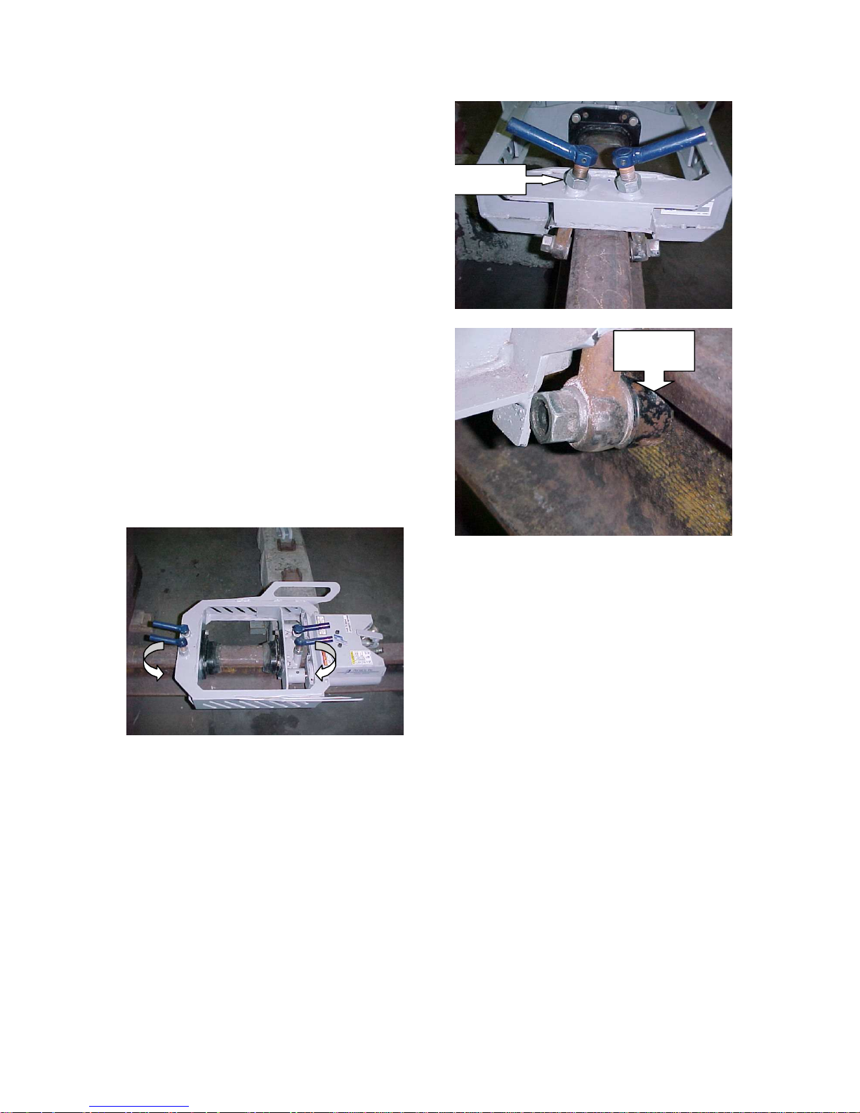
3.4 Positioning on Rail
Place the shear over the weld,
centering the weld between the
shearing blades.
Turn the handle on all four rollers to
position each roller under the rail.
ADJUSTMENT
NUT
1/8"
CLEARANCE
Adjust the roller clearance to 1/8"
below the ball of the rail using the
nut to maintain the clearance.
3.5 Connecting Hoses
WARNING: ALWAYS STOP THE
HYDRAULIC POWER SOURCE
FLOW AND DEPRESSURIZE THE
SYSTEM BEFORE CONNECTING
A TOOL. FAILURE TO COMPLY
COULD RESULT IN
PRESSURIZED FLUID
PENETRATING THE SKIN AND
INJECTED INTO THE BODY
CAUSING INJURY OR DEATH.
Wipe quick couplers with a clean lint
free cloth before connecting them.
1. Stop the hydraulic power source.
2. Depressurize the system.
3. Allow system and hydraulic fluid
to cool if too hot to handle.
13

4. Securely connect the return (tank
R
"R") hose from the power source
to the tool.
5. Securely connect the supply
(pressure "P") hose from the
power source to the tool.
P
When connecting hoses from power
source to the tool. It is
recommended that you connect the
return hoses first and disconnect last
to minimize or avoid trapping
pressure within the tool.
When connecting the quick couplers,
the flow should run from male
coupler to the female coupler. The
female coupler on the tool is the
inlet. Quick couplers are marked
with a flow direction arrow.
CAUTION: DO NOT PULL ON
HOSES TO DRAG POWER TOOL.
and only requires the operator to
close the jaws. Once the weld has
been sheared the operator releases
the lever and the jaws automatically
return to full open.
1. Press the control lever down and
hold until the jaws have
completely closed.
2. Release the handle and the jaws
will automatically return to full
open.
3. Disconnect the hoses, see
section 3.7 in this manual for
proper procedure.
4. Turn the hold downs to release
the rail and lift the puller off.
3.7 Disconnecting Hoses:
1. Stop the hydraulic power source.
2. Depressurize the system
NOTE: When possible, connect the
free ends of uncoupled hoses to
prevent build up in the hoses. The
sun can also increase pressure in
the hoses and make connecting
them difficult.
3.6 Operating Instructions
PortaCo, Inc.'s weld shear is
equipped with an auto cycle valve,
3. Disconnect the supply (pressure
"P") hose to the power source
(pressure port) than from the tool
(“IN” port).
4. Disconnect the return (tank) hose
to the hydraulic power source
(return port) than from the tool
(“OUT” port).
14

5. To prevent contamination, always
install dust caps over the
hydraulic ports of the tool when
disconnected.
WARNING: IF INJURY RESULTS
FROM ESCAPING HYDRAULIC
FLUID, SEEK IMMEDIATE
MEDICAL ATTENTION. SERIOUS
BODILY INJURY MAY OCCUR IF
PROPER MEDICAL ATTENTION IS
NOT ADMINISTERED
IMMEDIATELY.
WARNING: DO NOT ATTEMPT TO
LOCATE HYDRAULIC LEAKS BY
FEELING AROUND HOSES AND
FITTING WITH HANDS. ”PIN
HOLE” LEAKS CAN PENETRATE
THE SKIN.
3.8 Cold Weather Operation
Hydraulic fluids are thicker in cold
weather; therefore, run the engine at
low idle lone enough to bring the
fluid temperature up to minimum of
10°C/50 F or until the top of the
hydraulic tank feels warm, before
operating tool.
3.9 Storage Preparation
Store the weld shear on a smooth
level surface.
The tool should be stored in a cool,
dry environment which is not
subjected to rapid temperature
changes.
15
CAUTION: USE ONLY GENUINE PORTACO INC PARTS OR EQUIVALENT.
THE USE OF REPLACEMENT PARTS WHICH ARE NOT OF EQUIVALENT
QUALITY MAY DAMAGE THE HYDRAULIC POWER UNIT.
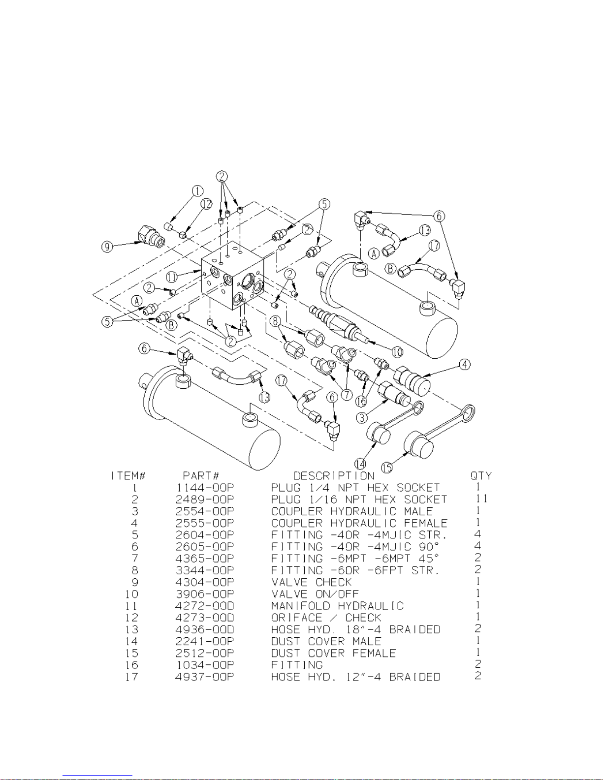
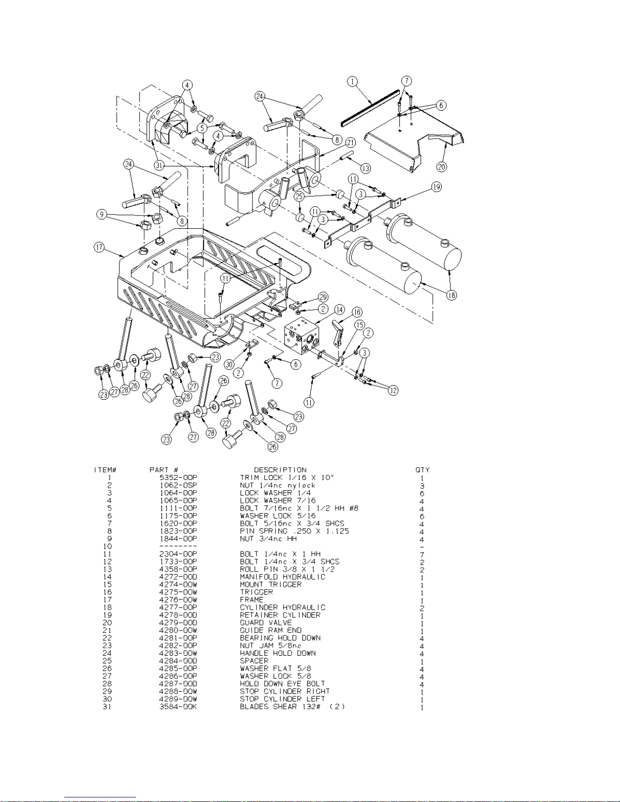
4.0 Maintenance Instruction
4.1 Assembly View and Parts List
16
17
4.2 Graphic Set Complete
(3494-00D)
2158-08D
2158-00D
2906-00D
3492-01D
3494-03D
3494-04D
3463-00D
18

4.3 Care Requirements
Monthly:
Maintenance
CLEANING AND MAINTENANCE
RECOMMENDATIONS Wipe all
external surfaces after each use with
a clean, lint free cloth to remove
surface contaminants from the tool.
Daily:
1. Wipe all tool surfaces, fittings,
and coupling free of grease, dirt,
and foreign materials.
WARNING: DO NOT ATTEMPT TO
LOCATE HYDRAULIC LEAKS BY
FEELING AROUND HOSES AND
FITTINGS WITH HANDS. “PINHOLE” LEAKS CAN PENETRATE
THE SKIN.
2. Inspect the tool signs of leaks
and worn, and/or damage
couplers. Replace if necessary.
3. To prevent contamination, always
install dust caps over the
hydraulic ports when
disconnected.
Inspect the hold down assemblies for
wear or damage and replace any
components as necessary to
maintain a good working condition.
Hold down service kits:
64-4294-OOK Roller bearing
replacement kit
64-4295-OOK Hold down bolt
replacement kit
Annually:
Remove the hydraulic system guard
and inspect fittings and tubing for
damage and replace as required.
Check linkage between valve and
lever for excessive wear and replace
as required.
NOTE: Do not attempt to repair this
product. Only properly trained
person should perform any
maintenance, service, and or repair
to a tool.
4. Inspect shear blades every day.
Replace as required.
COMPLETE DIASSEMBLY OF
THE TOOL IS NOT
RECOMMENDED. RETURN TO
PORTACO, INC. FOR REPAIRS.
19

4.4 Trouble Shooting
The following chart can be used as a guide to correct any problem you may
experience with the tool.
To determine the problem in operation of the weld shear always check that the
hydraulic power source is supplying the correct hydraulic flow and pressure to
the tool as listed in the table. Be sure you are using an accurate flow meter.
Check the flow with the hydraulic fluid temperature at least 80° F/27° C.
NOTE: Stop and depressurize the hydraulic system before connecting or
disconnecting a tool. Failure to follow these instructions can lead to severe
personal injury. Read and follow the instructions in this manual for the proper
way to connect and disconnect tools from the hydraulic systems.
PROBLEM CAUSE REMEDY
Shear binds or travels
jerky.
Hold downs are too tight. Adjust hold downs so
rollers are 1/8" below the
ball of the rail.
Hold downs are damaged Check for damage to the
hold down bolts or rollers.
Replace if required.
Air in system Run shear to full close
and hold for 10 seconds
to purge air.
If blades move but not
enough power to shear
weld.
Inspect shear blades for
wear or damage.
Hydraulic system leak. Check system for leaks
Replace shear blades if
required.
and repair as required.
Relief valve set to low on
power source.
Test power source and
repair or replace as
required.
Check lever linkage for
wear.
If lever bottoms before
full travel, replace or
repair control lever.
Leaky cylinder seal Perform test in section
2.3 of this manual.
Blades don't retract or
retract slowly
Control valve not
returning fully
Check that lever or valve
is returning completely.
Repair/ replace as
needed.
Hydraulic system leak. Check system for leaks
and repair as required.
20
Blades don't retract or
retract slowly.
Check valve malfunction. Remove check valve and
inspect for contamination.
Replace if required.
Shear blades close
completely but fails to
Damaged or worn shear
blades.
Replace shear blades.
shear weld.
Shear runs opposite to
control
Hoses hooked up to
wrong ports.
Check that hoses are
connect correctly.
NOTE: After reviewing trouble shooting chart and still unable to determine
problem call the service department at PortaCo Inc. (218-236-0223) for
assistance.
4.5 Technical Specifications
Weld Shear with blades 84-lbs/38.1 kg
Max Pressure 2000 psi/150 bar
Max Flow 10 gpm/40 lpm
21

Consumable Items List
Description Part Number Source
Coupler HYD FF-372-6FP M 2554-00P PortaCo Inc.
Coupler HYD FF-371-6FP F 2555-00P PortaCo Inc.
Cover Coupler # NR-37 BRUNNING 2241-00P PortaCo Inc.
Cover Coupler # NR-50 2512-00P PortaCo Inc.
Shear Blade Kit 3584-OOK PortaCo Inc.
Hydraulic Fluid Requirements
Viscosity (Fluid Thickness)
METRIC U.S.A.
10 C 95 Centistokes 50 F 450 SSU Max
38 C 27-42 C.S. 100 F 130-200 SSU
60 C 16.5 C.S., Min. 140 F 85 SSU Min.
Pour Point – 10 F/-23 C Minimum (for cold startup)
Viscosity Index (ASTM D 2220) 140 Minimum
Demulsibility (ASTM D-1401) 30 Minutes Maximum
Flash Point (ASTM D-92) 340 F/171 C Minimum
Rust Inhibition (ASTM D-665 A & B) Pass
Oxidation (ASTM D943) 1000 Hours Minimum
Pump West Test (ASTM D2882) 60 mg Maximum
Recommend Hydraulic Fluids
Type Hydraulic fluid
Chevron “Clarity” AW ISO 32
Exxon “Univis” J 32
Mobil D.T.E. 13 M
Gulf “Harmony” AW-HVI-150-32
Shell “Tellus T” 32
Texaco “Rando” HDZ 32
Union “Unax” AW-WR-32
Amsoil AWH ISO 32
Sunvis Low Pour H/032-product code 193000
Coupler recommendation: 3/8 inch FLAT FACE HTMA couplers rated at 2500 psi
working pressure. Threads are to match fittings used on hoses or fittings used
as adapters.
Bolt Size Torque
#10-32
¼-20
5/16-18
3/8-16
38 in. lbs.
76 in. lbs.
13 ft. lbs.
23 ft. lbs
22

SERVICE AND REPAIR NOTES
________________________________________________________________
________________________________________________________________
________________________________________________________________
________________________________________________________________
________________________________________________________________
________________________________________________________________
________________________________________________________________
________________________________________________________________
________________________________________________________________
________________________________________________________________
________________________________________________________________
________________________________________________________________
________________________________________________________________
________________________________________________________________
________________________________________________________________
________________________________________________________________
________________________________________________________________
________________________________________________________________
________________________________________________________________
________________________________________________________________
________________________________________________________________
________________________________________________________________
________________________________________________________________
________________________________________________________________
________________________________________________________________
________________________________________________________________
________________________________________________________________
________________________________________________________________
________________________________________________________________
23

MODEL
WS-10-64-3
WELD SHEAR
1805 2ndAVENUE NORTH * MOORHEAD, MN, USA 56560-2310
E-MAIL ADDRESS; info@portaco.com * INTERNET ADDRESS: www.portaco.com
OPERATION,
MAINTENANCE,
AND REPAIR
MANUAL
PHONE (218) 236-0223 * FAX (218) 233-5281
1

TABLE OF CONTENTS
1.0 Introduction
1.1 General Information
1.2 Features
1.3 Safety Summary
1.4 General Safety Precautions
1.5 Warning and Caution Statements
1.6 Training Requirements
2.0 Installation Instructions
2.1 Unpacking Instructions
2.2 Tool Preparations
2.3 Testing
2.4 Hose Requirements
2.5 Hydraulic Fluid Recommendations
2.6 Tool Connecting Procedures
2.7 Work Area Safety Precautions
3.0 Operating Instructions
3.1 Description of Power Unit
3.2 Controls and Graphics
3.3 Before Operating
3.4 Positioning on Rail
3.5 Connecting Hoses
3.6 Operating Instructions
3.7 Disconnecting Hoses
3.8 Cold Weather Operation
3.9 Storage Preparation
4.0 Maintenance Instructions
4.1 Assembly View and Parts List
4.2 Graphic Set Complete
4.3 Tool Maintenance
4.4 Trouble Shooting
4.5 Technical Specification
2

1.0 INTRODUCTION
C
1.1 General Information
This manual presents removal,
operation, and maintenance
information for PortaCo’s model
WS-10-64-3 Weld Shear. The tool is
designed to remove the excess
material when performing Thermit
and Buta type welds. It's light weight
compact size allows for use inside
rail pulling equipment. All hydraulic
plumbing is protected by a one piece
guard to prevent damage and to
contain any leaks if any damage
occurs. When properly used this tool
will help reduce back strain and also
reduce operator fatigue.
shearing blades to the full open
position when the valve control lever
is released. (See figure 1.2A arrow
A) This reduces total shearing time
and reduces the operator's exposure
to the heat produced during the
welding procedure.
B
A
Figure 1.2A
PortaCo, Inc. reserves the right to
make changes at anytime without
notice and without incurring any
obligation.
1.2 Features
The main features of the PortaCo
Weld Shear Model WS-00-64-3 are
as follows.
Standard unit:
Length 26.38 in/ 67.0 cm
Width 17.75 in/ 45.1 cm
Height 7.21 in/ 18.3 cm
Weight 84-lbs/ 38.1 kg
(includes blades)
Upper ambient operating
temperature 110°F (43° C), lower
ambient operating temperature -20°F
(-28° C).
PortaCo, Inc.'s weld shear features
an auto cycle valve which returns the
The control valve also limits the
speed for shearing and provides a
rapid retract for easy operation.
The hydraulic plumbing is protected
by a one-piece guard to prevent
damage and to contain any leaks if
any damage occures. (figure 1.2A
arrow B)
The hydraulic quick connect couplers
are located at the rear of the shear
and directs the hoses along the rail
out of the work area. (figure 1.2A
arrow C) The path of the hose's
along the rail reduces the potential
for a worker to trip on them.
Roller hold-downs, provide a secure
mount to the rail and allows smooth
operation during the shearing
process. The roller height is set with
a jam nut providing a snug fit on any
size rail. (figure 1.2B arrow A)
3

The roller assembly is easily
A
B
removed for replacement of any
component of the hold-down
assembly. (figure 1.2B arrow B)
Figure 1.2B
Handles incorporated into the frame
allow for even balance and level
transportation for quick positioning
on the rail. Figure 1.3
and before performing maintenance
or repairs. Supervising personnel
should develop additional
precautions relating to the specific
work area and local safety
regulations.
1.4 General Safety Precautions
The PortaCo Inc. tools are designed
to provide safe and dependable
service if operated according to the
instructions provided in this manual.
Read and understand this manual
and any stickers attached to the
power unit before operating. Failure
to do so could result in personal
injury or equipment damage.
Check the rules and regulations at
your location. The rules may include
an employer’s work safety program.
Regulations may identify hazards
such as working around utility supply
lines or hazardous slopes.
1.3 Safety Summary
Tool operators and maintenance
personnel must always comply with
the safety precautions given in this
manual and on the stickers and tags
attached to the tool and hoses.
These safety precautions are given
for your safety. Review them
carefully before operating the tool
Read and understand any manuals
for additional or optional equipment,
which maybe shipped with the tool.
1.5 Warning and Caution
Statements
Warning and Caution statements
have been strategically placed
throughout the text prior to operating
or maintenance procedures,
practices, or conditions considered
essential for the protection of
personnel, equipment, and property.
WARNING: HIGHLIGHTS A,
ESSENTIAL OPERATING, OR
MAINTENANCE PROCEDURE,
PRACTICE, CONDITION
STATEMENT, ETC… WHICH IF
NOT STRICTLY OBSERVED,
4

COULD RESULT IN INJURY TO,
OR DEATH OF, PERSONNEL OR
LONG TERM HEALTH HAZARDS.
CAUTION: HIGHLIGHTS AN
ESSENTIAL OPERATING OR
MAINTENANCE PROCEDURE,
PRACTICE, CONDITION
STATEMENT, ETC. WHICH IF NOT
STRICTLY OBSERVED, COULD
RESULT IN DAMAGE TO, OR
DESTRUCTION OF, EQUIPMENT
OR LOSS OF MISSION
EFFECTIVENESS.
1.6 Training Requirements
Operator training for the weld shear
should consist of information found
in this manual. In addition the
operator must receive instructions,
both verbally and through
demonstrations for applications in
which the tool is going to be used.
The new operator must start in an
area without bystanders and use the
tool until able to fully operate the tool
under the conditions for the work
area.
2.0 INSTALLATION INSTRUCTIONS
2.1 Unpacking Instructions
Upon receiving your weld shear
promptly remove it from the shipping
container. Always keep top side of
container up. Inspect unit for
damage which may have incurred
during shipping and report it to
carrier for claim.
2.2 Tool Preparations
The PortaCo G-18D55-53-W power
unit is recommended for hydraulic
supply. This unit is equipped with
two 5-gpm/20 lpm circuits that can
be combined for on 10 gpm/40 lpm
circuits.
If the tool is used in cold weather,
preheat the hydraulic fluid by running
power source at low engine speed.
Fluid temperature should be at or
above 50° F/10° C (400-ssu/82
centistroke) before use, when using
recommended fluids. Using too thick
of fluid may result in tool damage.
2.3 Testing
WARNING: NEVER STICK
FOREIGN OBJECTS, FINGERS,
OR OTHER EXTRMITIES INTO
MOVING MECHANISMS. FAILURE
TO FOLLOW THESE
INSTRUCTIONS MAY LEAD TO
SEVERE PERSONAL INJURY OR
TOOL DAMAGE.
Before operating the weld shear it is
important to inspect the shear blades
for excessive wear or damage.
Replace the shear blades if required
before operating the shear. Follow all
safety precautions and procedures
when inspecting tool.
To test the function of the shear,
connect the hydraulic hoses to the
tool see section 2.6 of this manual
for proper procedure. With the flow
from the power source "on" press the
control lever down and hold it there.
(See figure 2.3A) The shear blades
should close at a slow rate of speed.
Allow the blades to contact each
other. Release the lever and the
shear blades should move to full
open without touching the lever or
any form of assistance.
5

If the shear fails to complete any of
these functions see the trouble
shooting section of this manual.
Figure 2.3A
CAUTION: THE PRESSURE
TESTING PROCEDURE MUST BE
CONDUCTED BY A QUALIFIED
HYDRAULIC TECHNICIAN.
To test the pressure exerted at the
shear blades, disconnect the shear
from the power source. Remove the
shear blades from the frame.
The needle should be within 500 psi
of the red arrow. (figure 2.3C) When
testing follow the instructions
provided with the test equipment.
Testers other than PortaCo. Inc.'s
model TS-00-XX-O may instruct the
technician to perform the test in a
manor slightly different than the
procedure just described.
Figure 2.3B
Insert a pressure testing system
between the frame and the ram end
frame of the shear. PortaCo's Model
TS-00-X-O Tester Shear, is
recommended for this procedure.
(see figure 2.3B)
The model TS-00-X-O tester is
capable of testing most shears. It
features a pressure gauge with and
arrow indicating the optimum force
applied.
Position tester while closing the
shearing mechanism, aligning the
pins in the frames with the holes in
the tester. Hold the control lever
down till the needle, on the pressure
gauge, of the tester stops climbing.
Figure 2.3C
CAUTION: WHEN TESTING THE
RAIL SHEAR, BE SURE TO
FOLLOW ALL SAFETY
GUIDELINES.
2.4 Hose Requirements
It is not often necessary or advisable
to use long hoses. All hoses must
have an oil resistant inner surface
and an abrasion resistant outer
6

surface. Each hose must have male
FLOW PER CIRCUIT
SAE SPEC HOSE
pipe ends for most application.
Longer hoses can be used when
necessary, but can affect the
operation of the engine due to
resistance in the hose.
If small diameter or long hoses are
used, or if restrictive fittings are
connected to the supply and return
ports, the pressure required to push
the fluid through the system and
back to the tank will be higher. This
will reduce tool power.
HOSE TYPES
Hydraulic hose types authorized for
use by PortaCo, Inc. is as follows:
1. Labeled and certified nonconductive
2. Wire braided (conductive)
3. Fabric braided (not certified or
labeled non-conductive)
Hose 1: Listed above is the only
hose authorized for use near
electrical conductors.
*Important – Oil should always
flow from the male coupler
through the female coupler.
NOTE: The pressure increase in
uncoupled hoses left in the sun may
make them difficult to connect.
When possible after use, connect the
free ends of the operating hoses
Hoses 2 and 3: Listed above are
conductive and must never be used
near electrical conductors.
HOSE PRESSURE RATING
The rated working pressure of the
hydraulic hose must be at least 175
bar (2500 psi).
together.
HYDRAULIC HOSE RECOMMENDATION
Table 2.4
LENGTH EACH HOSE USE INSIDE DIAMETER
GPM LPM FEET METERS INCH MM
5 to 8 19 to 30 To 50 To 15 Both ½ 13 SAE 100R1-8 100R7-8
5 to 8 19 to 30 51-100 15 to 30 Both 5/8 16 SAE 100R2-10 SAE 100R8-10
5 to 8 19 to 30 100-300 30 to 90 Pressure
Return
9 to 12 34 to 45 To 50 To 15 Both 5/8 16 SAE 100R2-10 SAE 100R8-10
9 to 12 34 to 45 51-100 15 to 30 Pressure
Return
9 to 12 24 to 45 100-200 30 to 60 Pressure
Return¾1
5/8
¾
5/8
¾
16
19
16
19
19
25.4
(WIRE DRAID)
SAE 100R2-10
SAE 100R1-12
SAE 100R2-10
SAE 100R3-12
SAE 100R2-12
SAE 100R1-16
SAE SPEC
HOSE (FIBER
BRAID)
SAE 100R8-10
SAE 100R7-12
SAE 100R8-10
SAE 100R7-12
SAE 100R8-12
SAE 100R7-16
2.5 Hydraulic Fluid Recommendation
Inspect hose for cuts, crushing, leaks,
or abrasion which maybe a safety
hazard or reduce fluid flows.
The following fluids work well over a
Wide temperature range at startup,
Allow moisture to settle out, and resist
Biological growth likely in cool operating
Hydraulic circuits. These fluids are
Recommended by PortaCo inc. Other
That meets or exceeds the specifications
of these fluids may also be used.
7

Type Hydraulic fluid
Chevron “Clarity” AW 15032
Exxon “Univis” J 32
Mobil D.T.E. 13 M
Gulf “Harmony” AW-HVI-150-32
Shell “Tellus T” 32
Texaco “Rando” HDZ 32
Union “Unax” AW-WR-32
Amsoil AWH 15032
Sunvis
Low Pour H/032-product code 19300
Hydraulic fluid requirements:
WARNING: PRESSURIZED FLUID
ESCAPING FROM A DAMAGED
HOSE CAN PENETRATE THE
SKIN AND BE INJECTED IN THE
BODY CAUSING INJURY OR
DEATH.
CAUTION: DO NOT PULL ON
HOSES TO DRAG POWER UNIT.
a) Viscosity (fluid Thickness)
USA METRIC
50 F 4450 SSU Max 10 C 95 Centistokes
100 F 130-200 SSU 38 C 27-42 C.S.
140 F 85 SSU Min. 60 C 16.5 C.S, Min.
Pour Point- 10 F/-23 C Minimum (for cold startup)
Viscosity Index (ASTM D 2220) 140Minimum
Demulsibility(ASTM D-1401) 30 Minutes
Maximum
Flash Point (ASTM D-92) 340 F/171 C Minimum
Rust Inhibition (ASTM D-665 A & B) Pass
Oxidation(ASTM D943) 1000 Hours Minimum
Pump Wear Test (ASTM D2882) 60 mg
Maximum
2.6 Tool Connecting Procedures
Stop the engine before connecting
the tool and, or hoses to the power
unit, and when switching hoses or
tools. Turn the hydraulic on/off valve
to the off position before starting the
engine. Make sure all hose are
connected for correct flow direction
to and from the tool being used.
When routing hose in the work area,
position them where personnel will
not be at risk of tripping over them or
where vehicles can run over the
hoses. Do not lay hose over sharp
objects.
2.7 Work Area Safety Precautions
- Never operate the tool when you
are tired, angry, emotionally
disturbed, or under the influence
of alcohol, drugs, medications, or
anything that could affect your
vision, alertness, coordination or
judgement.
- Establish a training program for all
operators to ensure safe
operation.
- Do no operate the tool unless
thoroughly trained or under the
supervision of an instructor.
- Do not allow others to be near the
tool when starting it or while
operating. Keep bystanders and
animals out of the work area.
- Always wear safety goggles, ear,
leg, and head protection devices,
safety footwear, and snug fitting
clothes.
- Do not operate the tool near
energized transmission lines.
- Do not overreach. Maintain
proper footing and balance at all
times.
8

- Be sure to keep hands and other
parts clear and free from all
moving parts.
- Keep all body parts away from
moving jaws.
- Always connect hydraulic hoses to
the tool before activating the
hydraulic circuit on your power
unit. Check that hydraulic
couplers are secure before
activating the circuit.
- Only a properly trained person
should perform any maintenance,
service, and or repairs to a tool.
- Never operate a tool that is
damaged, improperly adjusted, or
not completely and securely
assembled.
- Do not operate the tool until you
have a clear work area and a
secure balance.
- Keep handles clean and dry.
- Never carry or pick this tool up by
the hydraulic hose
- Disconnect tool from hydraulic
source before inspection or
cleaning.
SAFETY REGULATION
Enter below any local or other safety regulations required for the operator to
follow. Make sure the operator and maintenance personnel have knowledge of
these regulations.
________________________________________________________________
________________________________________________________________
________________________________________________________________
________________________________________________________________
________________________________________________________________
________________________________________________________________
________________________________________________________________
________________________________________________________________
________________________________________________________________
________________________________________________________________
________________________________________________________________
________________________________________________________________
________________________________________________________________
________________________________________________________________
9

3.0 Operating Instructions
3.1 Description of Power Tool
PortaCo’s model WS-10-64-3 Weld
Shear is intended to be used to
shear Thermit and Buta type welds.
It's light-weight construction and
auto cycle valve reduces operator
fatigue.
PSI). The maximum pressure of the
hydraulic system is limited to 148.3
BAR (2150 PSI). The power source
provided the required flow and
pressure to operated HTMA type I
15-23 LPM (4-6 GPM) and type RR
34-40 LPM (9-10.5) tools. All which,
are OPEN-CENTER tools required
an operating pressure of 138 BAR
(2000 PSI).
The closing rate of the shear
blades, are limited to the industries
standard and cannot be altered.
When the control lever is release
the blades automatically retract at a
more rapid rate to reduce shearing
time.
The PortaCo Weld Shear secures to
the rail at four points. Adjustable
roller hold downs provide a smooth
shearing operation and guide the
shear on worn rail. Hold down
assemblies have been designed to
be easily serviced in the field.
Hydraulic quick connect couplers
are located at the rear of the tool to
allow more convenient routing of the
supply hoses.
Fully guarded hydraulic plumbing
protects the operator from
accidental leakage of oil onto the
welded area, reducing the potential
for a fire.
The G-18D55-53-W is a versatile
power unit that can meet the needs
for most hydraulic tools used by the
rail road industry. This power unit is
capable of powering two tools
simultaneously at 5 GPM (20 LPM)
or one tool a 10 GPM (40 LPM) all
the flows are at 138 BAR (2000
3.2 Controls and Graphics
The following decals are placed on
the tool to aid in its operation and
maintenance. The operator should
locate and understand them before
using this power tool.
The weld shear has five instructional
decals located on the tool.
On the hydraulic system guard cover
there is a CAUTION decal that
specifies that the weld shear is rated
for a flow of 10 GPM/40 LPM and
pressure of 2000 PSI/150 BAR do
not exceed these flow / pressure
ratings. Also on the decal is a few
written warnings “improper use may
cause severe injury, read and
understand operators manual before
operating tool, keep all guards in
place, during operation always wear
gloves, safe clothing and footwear,
and during operation always wear
approved safety protection for ears,
eyes, and head.” (figure 3.2A) (figure
3.2F arrow A)
10

Figure 3.2A
Figure 3.2C
The valve lever operating instruction
decal is located to the right of the
control and instructs the operator to
"PUSH TO SHEAR, AUTOMATIC
RETURN".(figure 3.2B)(figure 3.2F
arrow B)
Figure 3.2B
The "WARNING' decal indicates a
practice which if conducted could
result in injury to the operator or
bystander, or damage to the tool.
Follow the instructions "DO NOT
OPERATE SHEAR WITHOUT
SHIELD IN PLACE" and "DO NOT
STRIKE HOLD DOWNS" printed on
this decal. (figure 3.2C) (figure 3.2F
arrow C).
The mounting instructions decal is
also located on the guard cover. It
states the correct procedure for
adjusting the hold down rollers.
It tells the operator to "ADJUST
ROLLER CLEARANCE TO 1/8"
BELOW BALL OF RAIL". (figure
3.2D)(figure 3.2F arrow D)
Figure 3.2D
On the inside of the far side of the
frame, is a serial # decal. This decal
has the serial number as well as the
model number of the unit. Each unit
has it’s own unique serial number. It
is important to keep this decal
protected and kept legible. The
serial number is needed when
ordering replacement parts.
(figure 3.2E)(figure 3.2G arrow E)
11

ABC
D
a leak is present, hydraulic oil on the
weld area is flammable.
Inspect the hold down assemblies,
make sure they all operate properly.
Replace any damaged or severely
worn components before operation.
Hold downs which aren't operating
correctly may result in an inferior
sheared weld.
Figure 3.2E
Figure 3.2F
Inspect the shear blades and replace
if severely worn or damaged.
BAD "REPLACE"
Figure 3.2G
3.3 Before Operating
Check that the guard is in position
and securely fastened, and in good
condition. Inspect the weld shear for
any hydraulic oil leaks and repair as
required, Do Not operate the shear if
E
GOOD
Inspect hoses, which connect weld
shear to power source for wear,
cracking, fatigue, or leaks before
using. Also check that couplers are
in good condition.
12

WARNING: NEVER INSPECT
PRESSURIZED HOSES,
COUPLERS, OR FITTINGS WITH
HANDS OR AT CLOSE
DISTANCES. PRESSURIZED
FLUID CAN PUNCTURE THE SKIN
AND INJECT OIL INTO THE BODY
RESULTING IN DEATH.
Do not use hoses, couplers, or
fittings which are damaged, replace
immediately.
3.4 Positioning on Rail
Place the shear over the weld,
centering the weld between the
shearing blades.
Turn the handle on all four rollers to
position each roller under the rail.
ADJUSTMENT
NUT
1/8"
CLEARANCE
Adjust the roller clearance to 1/8"
below the ball of the rail using the
nut to maintain the clearance.
3.5 Connecting Hoses
WARNING: ALWAYS STOP THE
HYDRAULIC POWER SOURCE
FLOW AND DEPRESSURIZE THE
SYSTEM BEFORE CONNECTING
A TOOL. FAILURE TO COMPLY
COULD RESULT IN
PRESSURIZED FLUID
PENETRATING THE SKIN AND
INJECTED INTO THE BODY
CAUSING INJURY OR DEATH.
Wipe quick couplers with a clean lint
free cloth before connecting them.
1. Stop the hydraulic power source.
2. Depressurize the system.
3. Allow system and hydraulic fluid
to cool if too hot to handle.
13

4. Securely connect the return (tank
R
"R") hose from the power source
to the tool.
5. Securely connect the supply
(pressure "P") hose from the
power source to the tool.
P
When connecting hoses from power
source to the tool. It is
recommended that you connect the
return hoses first and disconnect last
to minimize or avoid trapping
pressure within the tool.
When connecting the quick couplers,
the flow should run from male
coupler to the female coupler. The
female coupler on the tool is the
inlet. Quick couplers are marked
with a flow direction arrow.
CAUTION: DO NOT PULL ON
HOSES TO DRAG POWER TOOL.
and only requires the operator to
close the jaws. Once the weld has
been sheared the operator releases
the lever and the jaws automatically
return to full open.
1. Press the control lever down and
hold until the jaws have
completely closed.
2. Release the handle and the jaws
will automatically return to full
open.
3. Disconnect the hoses, see
section 3.7 in this manual for
proper procedure.
4. Turn the hold downs to release
the rail and lift the puller off.
3.7 Disconnecting Hoses:
1. Stop the hydraulic power source.
2. Depressurize the system
NOTE: When possible, connect the
free ends of uncoupled hoses to
prevent build up in the hoses. The
sun can also increase pressure in
the hoses and make connecting
them difficult.
3.6 Operating Instructions
PortaCo, Inc.'s weld shear is
equipped with an auto cycle valve,
3. Disconnect the supply (pressure
"P") hose to the power source
(pressure port) than from the tool
(“IN” port).
4. Disconnect the return (tank) hose
to the hydraulic power source
(return port) than from the tool
(“OUT” port).
14

5. To prevent contamination, always
install dust caps over the
hydraulic ports of the tool when
disconnected.
WARNING: IF INJURY RESULTS
FROM ESCAPING HYDRAULIC
FLUID, SEEK IMMEDIATE
MEDICAL ATTENTION. SERIOUS
BODILY INJURY MAY OCCUR IF
PROPER MEDICAL ATTENTION IS
NOT ADMINISTERED
IMMEDIATELY.
WARNING: DO NOT ATTEMPT TO
LOCATE HYDRAULIC LEAKS BY
FEELING AROUND HOSES AND
FITTING WITH HANDS. ”PIN
HOLE” LEAKS CAN PENETRATE
THE SKIN.
3.8 Cold Weather Operation
Hydraulic fluids are thicker in cold
weather; therefore, run the engine at
low idle lone enough to bring the
fluid temperature up to minimum of
10°C/50 F or until the top of the
hydraulic tank feels warm, before
operating tool.
3.9 Storage Preparation
Store the weld shear on a smooth
level surface.
The tool should be stored in a cool,
dry environment which is not
subjected to rapid temperature
changes.
15

CAUTION: USE ONLY GENUINE PORTACO INC PARTS OR EQUIVALENT.
THE USE OF REPLACEMENT PARTS WHICH ARE NOT OF EQUIVALENT
QUALITY MAY DAMAGE THE HYDRAULIC POWER UNIT.
4.0 Maintenance Instruction
4.1 Assembly View and Parts List
16

17

4.2 Graphic Set Complete
(3494-00D)
2158-08D
2158-00D
2906-00D
3492-01D
3494-03D
3494-04D
3463-00D
18

4.3 Care Requirements
Monthly:
Maintenance
CLEANING AND MAINTENANCE
RECOMMENDATIONS Wipe all
external surfaces after each use with
a clean, lint free cloth to remove
surface contaminants from the tool.
Daily:
1. Wipe all tool surfaces, fittings,
and coupling free of grease, dirt,
and foreign materials.
WARNING: DO NOT ATTEMPT TO
LOCATE HYDRAULIC LEAKS BY
FEELING AROUND HOSES AND
FITTINGS WITH HANDS. “PINHOLE” LEAKS CAN PENETRATE
THE SKIN.
2. Inspect the tool signs of leaks
and worn, and/or damage
couplers. Replace if necessary.
3. To prevent contamination, always
install dust caps over the
hydraulic ports when
disconnected.
Inspect the hold down assemblies for
wear or damage and replace any
components as necessary to
maintain a good working condition.
Hold down service kits:
64-4294-OOK Roller bearing
replacement kit
64-4295-OOK Hold down bolt
replacement kit
Annually:
Remove the hydraulic system guard
and inspect fittings and tubing for
damage and replace as required.
Check linkage between valve and
lever for excessive wear and replace
as required.
NOTE: Do not attempt to repair this
product. Only properly trained
person should perform any
maintenance, service, and or repair
to a tool.
4. Inspect shear blades every day.
Replace as required.
COMPLETE DIASSEMBLY OF
THE TOOL IS NOT
RECOMMENDED. RETURN TO
PORTACO, INC. FOR REPAIRS.
19

4.4 Trouble Shooting
The following chart can be used as a guide to correct any problem you may
experience with the tool.
To determine the problem in operation of the weld shear always check that the
hydraulic power source is supplying the correct hydraulic flow and pressure to
the tool as listed in the table. Be sure you are using an accurate flow meter.
Check the flow with the hydraulic fluid temperature at least 80° F/27° C.
NOTE: Stop and depressurize the hydraulic system before connecting or
disconnecting a tool. Failure to follow these instructions can lead to severe
personal injury. Read and follow the instructions in this manual for the proper
way to connect and disconnect tools from the hydraulic systems.
PROBLEM CAUSE REMEDY
Shear binds or travels
jerky.
Hold downs are too tight. Adjust hold downs so
rollers are 1/8" below the
ball of the rail.
Hold downs are damaged Check for damage to the
hold down bolts or rollers.
Replace if required.
Air in system Run shear to full close
and hold for 10 seconds
to purge air.
If blades move but not
enough power to shear
weld.
Inspect shear blades for
wear or damage.
Hydraulic system leak. Check system for leaks
Replace shear blades if
required.
and repair as required.
Relief valve set to low on
power source.
Test power source and
repair or replace as
required.
Check lever linkage for
wear.
If lever bottoms before
full travel, replace or
repair control lever.
Leaky cylinder seal Perform test in section
2.3 of this manual.
Blades don't retract or
retract slowly
Control valve not
returning fully
Check that lever or valve
is returning completely.
Repair/ replace as
needed.
Hydraulic system leak. Check system for leaks
and repair as required.
20

Blades don't retract or
retract slowly.
Check valve malfunction. Remove check valve and
inspect for contamination.
Replace if required.
Shear blades close
completely but fails to
Damaged or worn shear
blades.
Replace shear blades.
shear weld.
Shear runs opposite to
control
Hoses hooked up to
wrong ports.
Check that hoses are
connect correctly.
NOTE: After reviewing trouble shooting chart and still unable to determine
problem call the service department at PortaCo Inc. (218-236-0223) for
assistance.
4.5 Technical Specifications
Weld Shear with blades 84-lbs/38.1 kg
Max Pressure 2000 psi/150 bar
Max Flow 10 gpm/40 lpm
21

Consumable Items List
Description Part Number Source
Coupler HYD FF-372-6FP M 2554-00P PortaCo Inc.
Coupler HYD FF-371-6FP F 2555-00P PortaCo Inc.
Cover Coupler # NR-37 BRUNNING 2241-00P PortaCo Inc.
Cover Coupler # NR-50 2512-00P PortaCo Inc.
Shear Blade Kit 3584-OOK PortaCo Inc.
Hydraulic Fluid Requirements
Viscosity (Fluid Thickness)
METRIC U.S.A.
10 C 95 Centistokes 50 F 450 SSU Max
38 C 27-42 C.S. 100 F 130-200 SSU
60 C 16.5 C.S., Min. 140 F 85 SSU Min.
Pour Point – 10 F/-23 C Minimum (for cold startup)
Viscosity Index (ASTM D 2220) 140 Minimum
Demulsibility (ASTM D-1401) 30 Minutes Maximum
Flash Point (ASTM D-92) 340 F/171 C Minimum
Rust Inhibition (ASTM D-665 A & B) Pass
Oxidation (ASTM D943) 1000 Hours Minimum
Pump West Test (ASTM D2882) 60 mg Maximum
Recommend Hydraulic Fluids
Type Hydraulic fluid
Chevron “Clarity” AW ISO 32
Exxon “Univis” J 32
Mobil D.T.E. 13 M
Gulf “Harmony” AW-HVI-150-32
Shell “Tellus T” 32
Texaco “Rando” HDZ 32
Union “Unax” AW-WR-32
Amsoil AWH ISO 32
Sunvis Low Pour H/032-product code 193000
Coupler recommendation: 3/8 inch FLAT FACE HTMA couplers rated at 2500 psi
working pressure. Threads are to match fittings used on hoses or fittings used
as adapters.
Bolt Size Torque
#10-32
¼-20
5/16-18
3/8-16
38 in. lbs.
76 in. lbs.
13 ft. lbs.
23 ft. lbs
22

SERVICE AND REPAIR NOTES
________________________________________________________________
________________________________________________________________
________________________________________________________________
________________________________________________________________
________________________________________________________________
________________________________________________________________
________________________________________________________________
________________________________________________________________
________________________________________________________________
________________________________________________________________
________________________________________________________________
________________________________________________________________
________________________________________________________________
________________________________________________________________
________________________________________________________________
________________________________________________________________
________________________________________________________________
________________________________________________________________
________________________________________________________________
________________________________________________________________
________________________________________________________________
________________________________________________________________
________________________________________________________________
________________________________________________________________
________________________________________________________________
________________________________________________________________
________________________________________________________________
________________________________________________________________
________________________________________________________________
23
 Loading...