

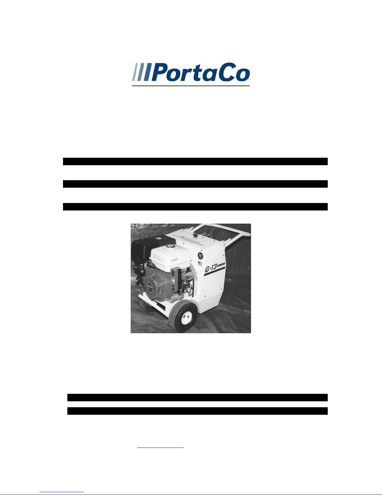
Hydraulic Power Unit
Pioneer Series
G-09, G-11, G-13
1805 2ndAVENUE NORTH * MOORHEAD, MN, USA 56560-2310
E-MAIL ADDRESS; info@portaco.com * INTERNET ADDRESS: www.portaco.com
OPERATION,
MAINTENANCE,
AND REPAIR MANUAL
PHONE (218) 236-0223 * FAX (218) 233-5281

2
TABLE OF CONTENTS
1.0 Introduction
1.1 General Information
1.2 Features
1.3 Options
1.4 Safety Summary
1.5 General Safety Precautions
1.6 Warning and Caution Statements
1.7 Training Requirements
2.0 Installation Instructions
2.1 Unpacking Instructions
2.2 Engine Preparation
2.3 Hydraulic Power Unit Preparation
2.4 Testing
2.5 Adjustments
2.6 Hose Requirements
2.7 Tool Connecting Procedures
2.8 Work Area Safety Precautions
3.0 Operating Instructions
3.1 Description of Power Unit
3.2 Controls and Graphics
3.3 Before Start Up
3.4 Positioning the Power Unit
3.5 Startup
3.6 Shutdown
3.7 Cold Weather Operation
3.8 Storage Preparation
4.0 Maintenance Instructions
4.1 Routine Servicing and Inspection
Schedule
4.2 Assembly View and Parts List
4.3 Hydraulic Fluids and engine
maintenance
4.4 Trouble Shooting
4.5 Technical Specifications

3
1.0 INTRODUCTION
1.1 General Information
CAUTION: DO NOT USE CLOSEDCENTER TOOLS WITH THIS
POWER UNIT
This manual presents installation,
operation, and maintenance information
for the Pioneer G-09, G-11, G-13 series
PortaCo Hydraulic Power Units. Model
G-09S06-52-W, G-11S07-52-W,
G-13S08-52-W.
PortaCo, Inc. reserves the right to make
changes at anytime without notice and
without incurring any obligation.
The Pioneer Power Unit is designed to
provide hydraulic flow and pressure for
operation of H.T.M.A. type I, II,
hydraulic tools.
The G-09506-52-W provides 5.9 gpm
(22.4 Liters) at 1800 psi (125 BAR) to
operate type I hydraulic tools. The
G-11507-52-W provides 7gpm
(26 Liters) at 2000 psi (148 BAR) to
operate type I hydraulic tools. The
G-13508-52-W provides 8 gpm (30.3
Liters) at 2000 psi (148 BAR) to operate
type II hydraulic tools.
For the G-11, and G-13 PortaCo power
units produce a maximum pressure of
148 BAR (2150 PSI). The G-09 power
unit produces a maximum pressure of
135 BAR (1950 PSI).
1.2 Features
The main features of the PortaCo
Pioneer G-09, G-11, and G-13 pioneer
series are as follows:
Standard unit is a wheeled style frame:
Length 67.3 cm (26.5 in.)
Width 50.8 cm (20 in.)
Height 69.8 cm (27.5 in.)
Weight 64.9 kg (143 lbs.)
Upper ambient operating
Temperature 43 C (110° F)
Lower ambient operating
Temperature -28°C (-20 F)
The Pioneer series comes with either a
Briggs & Stratton or a Honda Engine.
See the engine manual supplied with the
power unit for recommended fuel and
fuel restrictions.
The standard wheeled Pioneer series
power unit is equipped with collapsible
handle, which locks in place with a
latch, (see fig. 1.2A) and a lifting point
for a crane hook. (Fig. 1.2B)
The power units are all equipped with
air-to-oil coolers with suction fan
mounted to the power shaft on the
engine.
The fuel and hydraulic systems are selfcontained with the required reservoir,
filtration and level indicators.
(Fig. 1.2A)

4
LIFT HERE
1.3 Options
manual. Read and understand this
manual and any stickers attached to the
power unit before operating. Failure to
do so could result in personal injury or
equipment damage.
Check the rules and regulations at your
location. The rules may include
employer’s work safety program.
Regulations may identify hazards such
as working around utility supply lines or
hazardous slopes.
Read and understand any manuals for
additional or optional equipment, which
maybe shipped with the Pioneer power
unit.
Consult PortaCo. For special options that
may be available
1.4 Safety Summary
Tool operators and maintenance
personnel must always comply with the
safety precautions given in this manual
and on the stickers and tags attached to
the tool and hoses.
These safety precautions are given for
your safety. Review them carefully
before operating the power unit and
before performing maintenance or
repairs.
Supervising personnel should develop
additional precautions relating to the
specific work area and local safety
regulations.
1.5 General Safety Precautions
The PortaCo Inc. Pioneer G-09, G-11,
and G-13 Series Hydraulic Power Units
are designed to provide safe and
dependable service ifoperated according
to the instructions provided in this
1.6 Warning and Caution Precautions
Warning and Caution statements have
been strategically placed throughout the
text, prior to operating or maintenance
procedures, practices, or conditions,
considered essential to protection of
personnel or equipment and property.
WARNING: HIGHLIGHTS AN
ESSENTIAL OPERATING OR
MAINTENANCE PROCEDURE,
PRACTICE, CONDITION
STATEMENT, ETC. WHICH IF
NOT STRICTLY OBSERVED,
COULD RESULT IN INJURY TO,
OR DEATH OF, PERSONNEL OR
LONG TERM HEALTH HAZARDS.
CAUTION: HIGHLIGHTS AN
ESSENTIAL OPERATING OR
MAINTENANCE PROCEDURE,
PRACTICE, CONDITION
STATEMENT, ETC. WHICH IF
NOT STRICTLY OBSERVED,
COULD RESULT IN DAMAGE TO,
OR DESTRUCTION OF,

5
EQUIPMENT OR LOSS OF
MISSION EFFECTIVENESS.
See engine manual for recommended oil
and checking procedures.
1.7 Training Requirements
Operator training should consist of
information found in this manual for the
hydraulic power unit. In addition the
operator must receive instructions both
through demonstrations and verbally
with the tools or applications in which
the power unit is going to be used. The
new operator must start in an area
without bystanders and use all controls
until able to fully operate the power unit
under the conditions for the work area.
2.0 INSTALLATION
INSTRUCTIONS
2.1 Unpacking Instructions
Upon receiving your Pioneer hydraulic
power unit, promptly remove it from the
shipping container. Always keep top
side of container up. Inspect unit for
damage which may have incurred during
shipping and report it to carrier for
claim.
NOTE: clean up oil and fuel spills
immediately. Do not over fill fluids.
2.3 Hydraulic Power Unit Preparation
CAUTION: DO NOT OPERATE
POWER UNIT WITH BELOW
RECOMMENDED HYDRAULIC
OIL LEVEL. PUMP DAMAMAGE
MAY ACURE.
Check hydraulic fluid level by looking at
sight pipe located on top of the oil
reservoir. Proper oil level is indicated
when the center section of the sight pipe
is dark. To add hydraulic fluid remove
filter cap on top of reservoir, replace
when finished. Reservoir capacity is
18.9 LTR (5.0 gal) do not overfill fluids,
clean up oil spills immediately. Only
hydraulic fluids meeting the
specifications located below are
recommended for use with PortaCo
hydraulic power units.
(Fig. 2.3A)
2.2 Engine Preparation
CAUTION: READ AND
UNDERSTAND ENGINE MANUAL
WHICH IS PROVIDED IN
ADDITION TO THE PORTACO
MANUAL BEFORE STARTING
THE POWER UNIT.
CAUTION: ALWAYS CHECK
ENGINE OIL BEFORE STARTING
POWER UNIT.
Make sure engine oil is at the “FULL”
mark on the dipstick.
Viscosity (Fluid Thickness)
METRIC U.S.A.
10 C 95 Centistokes 50 F 450 SSU Max
38 C 27-42 C.S. 100 F 130-200 SSU
60 C 16.5 C.S, Min. 140 F 85 SSU Min.
Pour Point -10 F/23 C Minimum (for cold startup)
Viscosity Index(ASTM D 2220) 140 Minimum
Demulsibility(ASTM D-1401) 30 Minutes Maximum
Flash Point (ASTM D-92) 340 F/171 C Minimum
Rust Inhibition (ASTM D-665 A & B) Pass
Oxidation (ASTM D943) 1000 Hours Minimum
Pump Wear Test (ASTM D2882) 60 mg Maximum

6
The following fluids work well over a
Type
Hydraulic fluid
Chevron
“Clarity” AW 15032
Exxon
“Univis” J 32
Mobil
D.T.E. 13
M
Gulf
“Harmony” AW
-
HVI-150-32
Shell
“Tellus T” 32
Texaco
“Rando” HDZ 32
Union
“Unax” AW
-WR-32Amsoil
AWH 15032
Sunvis
Low Pour H/032
-
product code 19300
wide temperature range at startup, allow
moisture to settle out, and resist
biological growth likely in cool
operating hydraulic circuits. These
fluids are recommended by PortaCo, Inc.
Other fluids that meet or exceed the
specifications of these fluids may also be
used.
Fill the fuel reservoir to a level just
below the bottom of the filter tube.
Always use clean gasoline as
recommended in the engine manual. Do
not overfill fluids, clean up oil and fuel
spills immediately.
2.4 Testing
All power units are tested at the factory
and their flows and pressures are
recorded on the test report, which is
shipped with the power unit. Testing of
the power unit is not required unless it is
damaged during shipping.
of the hoses. Make sure flow
direction is correct.
c. Start the engine and allow the
hydraulic fluid to warm to about
100° F/38 C°.
d. Open the tester restrictor valve (fully
open.) This represents minimum
load.
e. Set the flow control to “ON” and set
engine throttle for maximum speed.
f. Check the flow rate and pressure on
the tester gauges. The back pressure
reading should be under 17.3 bar
(250 PSI). The flow readings should
match those listed in section 1.1
General Information of this manual.
g. With engine throttle set at maximum
speed slowly close the restrictor
valve on the tester while observing
the flow pressure gauges.
h. As the hydraulic system relief valve
begins to crack (open) and bypass
fluid through the valve, the flow rate
will begin to drop. At this time, the
pressure in the system should be
between 145-155 BAR (2100-2250
PSI).
i. If the pressure is not as specified, the
hydraulic circuit relief valve must be
adjusted or replaced. (See section
4.2 for procedure.)
- If the flow rate drops below the
specified range, the pump or
control valve may be worn.
Always perform “before startup
procedures” found in section 3.3 before
testing. PortaCo Hydraulic Tester, Part
Number T-00016-XX-0 is recommended
for all tests.
a. Set the hydraulic circuit to “OFF.”
b. Connect hydraulic hoses to the
power unit. Connect the PortaCo
Hydraulic Tester to the opposite end
- If the flow remains constant, but
pressure does not increase, the
relief valve may be defective.
2.5 Adjustments
The engine RPM’s and the hydraulic
system flow and pressure relief are set at
the factory and must not be readjusted.

7
DO NOT change governor setting or
tamper with governor components,
which may increase the governed engine
speed.
WARNING: OPERATING THE
POWER UNIT AT EXCESSIVE
SPEEDS INCREASE THE DANGER
OF PERSONAL INJURY.
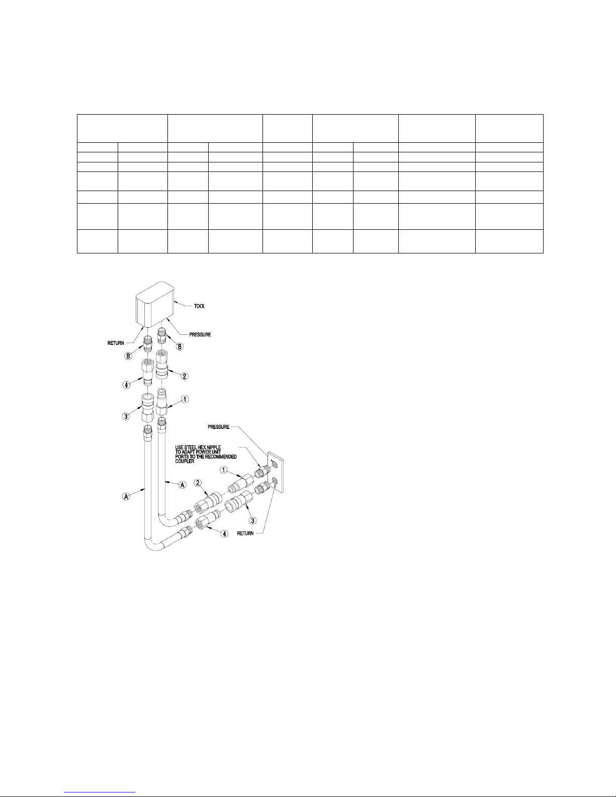
Two hoses are required to complete the
circuit, each hose should have a male
coupler on one end and a female coupler
on the opposite. See diagram on page 8
for hose routing.
*Important – Oil should always flow
from the male coupler through the
female coupler.
2.6 Hose Requirements
The Pioneer series are easily moved
close to the job site. It is not often
necessary or advisable to use long hoses.
All hoses must have an oil resistant inner
surface and an abrasion resistant outer
surface. Each hose must have male pipe
ends for most application. Longer hoses
can be used when necessary, but can
affect the operation of the tool due to
resistance in the hose.
If small diameter or long hoses are used,
or if restrictive fittings are connected to
the supply and return ports, the pressure
required, to push the fluid through the
system and back to the tank will be
higher. This will reduce tool power.
The pressure and return hose are
connected to the control block. A
½-inch male pipe hose end can be
connected, to H.T.M.A. flat-nosed
quick-disconnect couplings (available
through PortaCo, Inc).
The right port is the return port. A
female H.T.M.A. quick-disconnect
coupling should be connected to this
port.
NOTE: The pressure increase in
uncoupled hoses left in the sun may
make them difficult to connect. When
possible after use, connect the free ends
of the operating hoses together.
HOSE TYPES
Hydraulic hose types authorized for use
by PortaCo, Inc. are as follows:
1. Labeled and certified non-conductive
2. Wire braided (conductive)
3. Fabric braided (not certified or labeled non-
conductive)
Hose 1: Listed above is the only hose authorized
for use near electrical conductors.
Hoses 2 and 3: Listed above are conductive and
must never be used near electrical conductors.
HOSE PRESSURE RATING
The left port of the control block is the
pressure (oil out) fitting. A male
H.T.M.A. quick-disconnect coupling
(without lock ring) must be connected to
this port.
The rated working pressure of the
hydraulic hose must be at least 175 bar
(2500 PSI.)
8
HYDRAULIC HOSE RECOMMENDATIONS
Table 2.6A
FLOW PER CIRCUIT LENGTH EACH HOSE USE INSIDE DIAMETER SAE SPEC HOSE
GPM LPM FEET METERS INCH MM
5 to 8 19 to 30 To 50 To 15 Both 1/2 13 SAE 100R1-8 100R7-8
5 to 8 19 to 30 51-100 15 to 30 Both 5/8 16 SAE 100R2-10 SAE 100R8-10
5 to 8 19 to 30 100-300 30 to 90 Pressure
Return
9 to 12 34 to 45 To 50 To 15 Both 5/8 16 SAE 100R2-10 SAE 100R8-10
9 to 12 34 to 45 51-100 15 to 30 Pressure
Return
9 to 12 34 to 45 100-200 30 to 60 Pressure
Return
5/8
3/4
5/8
3/4
3/4
1
16
19
16
19
19
25.4
(WIRE BRAID)
SAE 100R2-10
SAE 100R1-12
SAE 100R2-10
SAE 100R3-12
SAE 100R2-12
SAE 100R1-16
SAE SPEC
HOSE (FIBER
BRAID)
SAE 100R8-10
SAE 100R7-12
SAE 100R8-10
SAE 100R7-12
SAE 100R8-12
SAE 100R7-16
FOR SINGLE CIRCUIT FLOWS UP TO
10 GPM plumb hose and tool as illustrated
in fig. 1. Numbers are represented below as
paragraph numbers.
1. H.T.M.A. 3/8-inch Male Quick Acting
Coupler with ½-inch NPT thread.
2. H.T.M.A. 3/8-inch Female Quick
Acting Coupler with ½-inch NPT
thread.
At the tool this may be H.T.M.A.
3/8-inch Female Quick Acting
Coupler with 3/8-inch NPT
thread.
3. H.T.M.A. 3/8-INCH Female
Quick Acting Coupler with ½-inch
NPT thread.
4. H.T.M.A. 3/8-inch Male Quick
Acting Coupler with ½-inch NPT
thread.
At the tool this may be 3/8-inch
Male Quick Acting Coupler with
3/8-inch NPT thread.
A. Refer to Table 2.6A for hose
recommendations
B. Use adapters with threads that
match tool port.

9
2.7 Tool Connecting Procedures.
Inspect hose for cuts, crushing, leaks, or
abrasion which maybe a safety hazard or
reduce fluid flows.
WARNING: DO NOT
ATTEMPT TO LOCATE
HYDRAULIC LEAKS BY FEELING
AROUND HOSES AND FITTING
WITH HANDS. “PIN-HOLE” LEAKS
CAN PENETRATE THE SKIN.
Stop the engine before connecting the
tool and, or hoses to the off power unit,
and when switching hoses or tools. Turn
the hydraulic on/off valve to the off
position before starting the engine.
Make sure all hoses are connected for
correct flow direction to and from the
tool being used. When routing hose in
the work area, position them where
personnel will not be at risk of tripping
over them or where vehicles can run
over the hoses. Do not lay hose over
sharp projects.
WARNING: PRESSURIZED FLUID
ESCAPING FROM A DAMAGED
HOSE CAN PENETRATE THE
SKIN AND BE INJECTED IN THE
BODY CAUSING INJURY OR
DEATH.
CAUTION: DO NOT PULL ON HOSES
TO DRAG POWER UNIT.
2.8 Work Area Safety Precautions
engine exhaust can be fatal.
- Keep clear of hot exhaust.
- Do not use PortaCo hydraulic
power units in potentially explosive
atmospheres such as near
wastewater drains or landfill sites.
- Do not operate if flammable gases
or vapors are present.
- Keep the power unit at least 1meter
(3.3 ft) away from buildings, obstructions,
and flammable objects. Do not aim engine
exhaust at materials that could catch fire.
- Allow the engine to cool before
storing the power unit in an
enclosed space.
- PortaCo hydraulic power units must
not be located below overhead
gantries, power lines, or walkways
where there might be a risk of
falling objects.
- Provide ambient light intensity of
200 Lux for working indoors or
outdoors particularly if working at
night.
- Always wear appropriate safety
equipment such as goggles, ear
protection, and foot protections.
- Operate only tools which fit into
the specifications prescribed in
section 1.1 of this manual.
- Never operate the power unit in a
closed space. Inhalation of
- Do not stand on power unit.

10
3.0 OPERATING INSTRUCTIONS
3.1 Description of Power Unit
The PortaCo Pioneer series
Hydraulic Power Unit has been designed
for the purpose of supplying hydraulic
fluid under pressure to power hydraulic
hand tools. The standard engine is a
Honda 9 hp, 11 hp, or 13 hp. depending
on the model of power unit purchased.
See section 1.2 features of this manual
for specifications. See the technical
manuals supplied by the engine
manufacture included with this power
unit for detailed technical specifications.
PortaCo Hydraulic Power Units have
been designed for use indoors and
outdoors. PortaCo power units should
not be operated under wet conditions, or
at ambient operating temperatures,
outside the recommended temperature
range of -28° C to 43° C. (-20° F to
110° F).
CAUTION: DO NOT USE CLOSEDCENTER TOOLS WITH THIS
POWER UNIT.
During operation, the engine may bog,
run at lower rpm, when under load. As
the tool being used is loaded, meets with
increase resistance, the pressure required
to operate the tool increases. The
increased pressure adds load to the pump
which loads the engine, there by
reducing the RPMS. As a result, the
flow will drop as pressure increases.
The hydraulic system has a pressure
limiter set at 148 BAR (2150 PSI) which
diverts the flow back to the tank until the
pressure drops below 148 BAR (2150
PSI.)
Tools with higher flow and, or pressure
requirements will not operate at their full
potential if used with the PortaCo
Hydraulic Power Unit. Tools with lower
flow and or pressure requirements may
be damaged if used with this power unit.
The engine throttle and the hydraulic
system relief value are preset at the
factory and must not be altered for any
reason without consulting PortaCo Inc.
Any alterations approved by PortaCo
Inc., can only be preformed by personnel
qualified to maintain hydraulic systems.
Tools which are commonly used with
PortaCo’s Pioneer series Hydraulic
power unit are as follows:
Impact Wrenches
Impact Drills
Picks
Handheld grinders
Breakers
Tampers
Hand Held Saws
Hand Held Pruners
Do not use the Pioneer series power unit
with close-center tools, tools which do
not allow the oil to return to the power
unit when not activated. Do not use in
jacking operations. Do not use to
activate cylinders without an inline
open-center control system. Do not
operate without a return oil hose.
If there are any doubts weather your tool
can be used with the Pioneer series unit
please contact the service department at
PortaCo Inc. (218-236-0223) for advice.
PortaCo Inc. accepts NO responsibility
for machines that are used for any
purpose other than the intended purpose
as specified in the operating instructions
or approved directly by PortaCo Inc.

11
3.2 Controls and Graphics
WARNING: FAILURE TO
FOLLOW THE PROCEDURES
LISTED IN THE ENGINE’S
OWNER’S MANUAL COULD
RESULT IN PERSONAL INJURY
OR EQUIPMENT DAMAGE.
Refer to the engine owner’s manual for
explanation of controls and symbols
located on the engine.
The following decals are placed on the
power unit to aid in its operation and
maintenance. The operator should locate
and understand them before using this
power unit.
(Fig. 3.2B)
A caution fan decal advises operators of
an area, which contains a potential
hazard if guards are not properly in
position. (Fig. 3.2A)
(Fig. 3.2A)
The hydraulic oil reservoir is marked
with a hydraulic oil decal (Fig. 3.2B)
and there is a hydraulic oil drain decal
indicating the tank’s drain plug (Fig.
3.2C)
(Fig 3.2C)
The hydraulic work ports are labeled
respectively as to their function with a
decal (Fig. 3.2D). The left port is
pressure and is equipped with a male
quick coupler. The right port is return
and is equipped with a female quick
coupler.
(Fig. 3.2D)
The hydraulic circuit on the pioneer
series power unit is controlled with a
rotary on-off knob. The rotation

12
directions for the on and off positions
are indicated by the decal on the knob
(Fig. 3.2E).
(Fig. 3.2 E)
A PortaCo serial number decal is
attached to the power unit on the back
side of the fuel tank. The serial number
tag displays PortaCo’s address and
phone number in addition to the units
model number, serial number, and other
technical specifications (Fig 3.2F).
(Fig. 3.2 G)
The caution do not touch hot surface
decal is located on the top of the hood
next to the engine (Fig 3.2 H).
(Fig. 3.2F)
The hydraulic fluid reservoir decal (Fig
3.2 G) is located on the hydraulic tank
next to the filter. The hydraulic fluid
reservoir decal tells when fluid should be
added by looking in the sight tube when
the engine is at idle.
(FIG. 3.2 H)
3.3 Before Start Up
Check engine oil level, and engine air
filter. Refer to the engine manual for
proper procedures when checking, filing,
cleaning, or replace any engine
components and fluids.
Check the hydraulic oil reservoir level.
Add oils as required to raise level to full
mark. Use only hydraulic fluids
recommended in section 2.3 of this
manual. Drain reservoir and change the
filter every 300 hrs. or yearly which ever
is more frequent. Hydraulic reservoir
holds 18.9 liters (5 gallons) and is

13
drained by removing a plug under the
tank. See section 4.3 for procedures.
Check that the fuel level is at an
adequate level before starting engine.
Before using the Pioneer power unit,
inspect the oil cooler grill for blocking
or contamination. The power units must
be free of leaves, dirt, oil, and other
contaminants, which may inhibit cooling
or create a fire hazard. Use compressed
air or a pressure washer to keep unit
clean.
Check that the battery terminals are
clean and free from any objects, which
could cause the battery to short out
which, could lead to fire or explosion.
Replace worn or damaged straps.
The Pioneer power unit can be pushed
around the work sight and be positioned
close to the work being done. To lock
the handle in position lift handle until
latches automatically catch on stops at
each end of handle. (Fig. 1.2A) To lower
the handle lift up on both latches at the
same time and let the handle drop down.
The Pioneer unit can also be position by
using a crane. The power unit has a
lifting point so it can be loaded easily or
positioned at the work sight with a crane.
(Fig 1.2B)
Place the PortaCo hydraulic Power Unit
on a level surface with no greater than a
20 degree slope to prevent fuel spillage
and power unit movement.
Check that fasteners and fittings are
tight, and tighten any fittings, which may
develop a leak or fasteners that may
become loose immediately. Hydraulic
hoses and couples should be inspected
for wear, cracking, or fatigue prior to
starting the engine.
WARNING: NEVER INSPECT
PRESSUREIZED HOSES,
COUPLERS, OR FITTINGS WITH
HANDS OR AT CLOSE
DISTANCES. PRESSURIZE FLUID
CAN PUNCTURE THE SKIN AND
INJECT OIL INTO THE BODY
RESULTING IN DEATH.
Do not use hoses, couples, or fittings
which are damaged, replace
immediately.
See section 2.8 of this manual for
additional safety procedures.
3.4 Positioning the Power Unit
WARNING: PLACING THE
PORTACO HYDRAULIC POWER
UNIT ON EXCESSIVE SLOPES OR
UNSTABLE GROUND COULD
CAUSE THE UNIT TO ROLL OR
TIP DAMAGING THE POWER
UNIT OR ENDANGERING
WORKERS.
Locate hydraulic power unit in well lit
area with a minimum ambient light
intensity of 200 lux weather indoors or
outdoors, particularly at night. Keep the
power unit at least 1 meter (3.3ft) away
from buildings, obstructions, and
flammable objects. Do not aim engine
exhaust at materials that could catch fire.
3.5 Start Up
(A)Observe all safety precautions found
through out this manual and the
included engine manual.
(B) Connect the hoses to the tool and
then to the power unit.

14
NOTE: Clean ends of couplers before
connecting to prevent system
contamination.
(C) For Pioneer series power units turn
the control value fully
counterclockwise (OFF). (See Fig.
3.5A)
(Fig. 3.5A)
(D)To start engine slide throttle knob
left slightly (Fig 3.5 B), then turn the
ignition key to start the engine (Fig
3.5 C). Allow the engine to run at
low speed until the engine and
hydraulic circuits are warm. Use
short starting cycles (15 secs. per
min.) to prolong starter life.
Extended cranking can damage
starter motor.
(Fig. 3.5 B)
(Fig. 3.5 C)
(E) Rotate the hydraulic control valve to
the “ON” position or on some
models select the flow required.
*Important – Make sure the control
value is in the OFF position before
connecting or disconnecting hoses to
the tool.
Tools used with the Pioneer power
unit must be designed for operation
with open-center systems.
3.6 Shutdown
A. NORMAL SHUTDOWN
1) Observe all safety precautions
2) Rotate hydraulic control valves to
the “OFF” position.
3) Slide the throttle lever to the idle
position.
4) Allow engine to idle for 2 to 3
minutes; then turn ignition “OFF”,
rotate counter clockwise.
5) Disconnect the hoses from the
power unit pressure hose first.
Then disconnect hoses from the
tool. When possible after use,
connect the free ends of the
operating hoses together. The

15
pressure increase in uncoupled
hoses left in the sun may make
them difficult to connect.
6) Allow the hydraulic power unit to
cool down before enclosing in a
small area for transportation or
storage.
B. EMERGENCY SHUTDOWN
In the event of an emergency,
immediately set the ignition switch to
“OFF”.
3.7. Cold Weather Operation
Hydraulic fluids are thicker in cold
weather; therefore, run the engine at low
idle long enough to bring the fluid
temperature up to minimum of 10°C/50°
F or until the hydraulic tank feels warm.
In cold weather, a cover over the cooler
will allow faster warm-up.
To prepare the engine for transportation
or storage refer to the engine owner's
manual. Remove the ground cable from
the battery.
To prepare the hydraulic system for
storage fill the hydraulic oil reservoir to
the full mark, and check that the fill cap
and filter are tight. When removing
from storage during a 3 month or longer
period, drain the water from the
hydraulic oil reservoir, if any
condensation has occurred, and replace
the hydraulic oil filter. (See section 4)
This will remove any water which may
have condensed in the hydraulic oil
reservoir during storage.
Store the PortaCo Pioneer hydraulic
power unit on a smooth level surface.
The power unit should be stored in a
cool, dry environment which is not
subjected to rapid temperature changes.
3.8 Storage Preparation

16
4.0 MAINTENANCE INSTRUCTIONS
Item
Action
Each use
First
Every 3
Every 6
Every year
Engine
Oil
Check
O
Change
OOAir Cleaner
Check
O
Change
O (1)
O *(1)
Replace
O**
Spark Plug
Check
O
Replace
O
Sediment
Clean
O
Spark
Clean
O
Idle speed
Adjust
O(2)
Fuel tank
Check
O (2)
Fuel
tube
Check
Every 2 years (
2)Valve
Check
O (2)
Combustion
Clean
After every
50
0 hours (
2
)
4.1 Routine Servicing and Inspections Schedule
Maintenance Schedule (Preformed at every indicated month or operating interval,
whichever comes first.)
cup
arrester
and filter
clearance
chamber
NOTE:
or 5 hrs.
month or
20 hrs.
months or
50 hrs.
months or
100 hrs.
or 300 hrs.
(1): Service more frequently when used in dusty areas
(2): These items should be serviced by your Honda servicing dealer, unless you
have the proper tools and are mechanically proficient. Refer to the Honda
shop manual for service procedures.
(3): For commercial use, log hours of operation to determine proper maintenance
intervals.
* Internal vent carburetor with dual element type only.
Cyclone type every 6 months or 150 hours
**Replace paper element type only
Cyclone type every 2 years or 600 hours
Lube Data
Engine Lube:
Capacity: 1 ¾ qts with filter Type: SAE 30……40 F & above
1 ½ qts without filter 5W-30……0 -40 F
SYNTHETIC
5W-20/5W-30……40 F & Below

17
Hydraulic System:
Capacity: 17 qts reservoir Type: viscosity grade 32
20 qts total system with filter
Service Replacements Parts
Description Part Number Source
Filter Hydraulic Oil
10 micron twist on
1083-OOP PortaCo Inc.
SPE-15-10 LHA

18
CAUTION: USE ONLY GENUINE PORTACO INC PARTS OR EQUIVALENT.
THE USE OF REPLACEMENT PARTS WHICH ARE NOT OF EQUIVALENT
QUALITY MAY DAMAGE THE HYDRAULIC POWER UNIT.
WARNING: UNAUTHORIZED MODIFICATIONS TO THE POWER UNIT
MAY IMPAIR THE FUNCTION AND/OR SAFETY AND IMPAIR MACHINE
LIFE. USE ONLY APPROVED SERVICE PARTS OR ACCESSORIES.
4.2 Assembly View and Parts List
G-09/G11/G13 SERIES
ITEM P/N DESCRIPTION QTY
1 1013-OOP FILTER 1
2 1041-OOP NUT JAM 17
3 1042-OOP BOLT 3/8 8
4 1044-OOP BOLT ¼ 21
5 1048-OOP PLUG MAGNET 1
6 1061-OOP NUT 3/8 6
7 1062-OOP NUT ¼ 11
8 1063-OOP WASHER LOCK 3/8 6
9 1064-OOP WASHER LOCK 1/4 31
10 1068-OOP FITTING 2
12 1080-OOP PIN COTTER 1/8 2
13 1085-OOP CLAMP 2
14 1093-OOP WASHER FLAT 3/8 6
15 1132-OOP FITTING 2
16 1146-OOP VALVE RELIEF 1
17 1285-OOP GAUGE HOUR METER 1
18 2057-OOP BOLT 1/4 2
19 1416-OOP CLAMP HOSE 4
20 1423-OOP STRAP 1
21 1444-OOP FITTING 3
22 1457-OOP TIE 8” 8
23 1505-OOP FITTING 1
24 1631-OOP NUT 3/8 4
25 1768-OOD GAUGE SIGHT 1
26 1871-OOP BOLT 3/8 2
27 1895-OOD LATCH HANDLE 2
28 1926-OOP CLAMP HOSE 2
29 1930-OOP CABLE POS. RED 1
30 1931-OOP CABLE NEG. BLACK 1
31 1940-OOP VALVE 1
32 1960-OOD SPACER HANDLE 2
33 2531-OOP FITTING 1
37 2187-OOP CAP 1
38 2368-OOD AXLE 1
39 2443-OOP WHEEL 2
40 2466-OOD CONTAINER 1
41 4366-OOP HOSE PRESSURE 1
42 2476-OOP FITTING 1
43 2490-OOP FITTING 1
44 2498-OOP TRIM 1
45 2651-OOP BUMPER HOOD 1

19
46 2701-OOP COUPLER HYD 1
47 2702-OOP COUPLER HYD 1
48 2780-OOP HANDLE 1
49 2781-OOD GRAPHIC SET 1
50 2782-OOD COUPLER PUMP DRIVE 1
51 2783-OOP HOSE SUCTION 1
52 2784-OOW TANK HYDRAULIC 1
53 2785-OOD SPACER AXLE 2
54 2786-OOW GRILL 1
55 2787-OOP GUARD FAN 1
56 2788-OOP COOLER HYDRAULIC 1
57 2789-OOP PUMP 9HP & 11 HP HONDA 1
2414-OOP PUMP 13 HP HONDA
58 2790-OOP HOSE HYDRAULIC RETURN 2
59 2791-OOP FAN 1
60 2792-OOD MANIFOLD HYDRAULIC 1
61 2793-OOP ENGINE HONDA 9 HP 1
2886-OOP ENGINE HONDA 11 HP
2890-OOP ENGINE HONDA 13 HP
62 2794-OOW HOOD 1
64 2796-OOP FITTING BUSHING 1
65 1929-OOP BATTERY 1
66 1083-OOP ELEMENT HYDRAULIC FILTER 1
67 KEY ENGINE/FAN 1
68 WIRE HOUR METER 1
69 2445-OOD SPACER 2
70 3496-OOP GROMMET 1
71 1733-OOP BOLT 3
72 2304-OOP BOLT 2
73 1099-OOP WASHER FLAT ¼ 2
74 2752-OOP SET SCREW 2
76 1221-OOP BOLT ¼ 3
77 3012-OOP CAP / PLUG 1
78 1544-OOP SHIM AS REQUIRED
79 1656-OOP WASHER FLAT 3/16 5
3612-OOD FAN GUARD 1
3613-OOW LIFTING EYE 1

20

21
4.3 HYDRAULIC FLUID AND
Temperature Range
Oil
5
° C (40° F) and above
S
AE 30
¯18° C
-
(0° F)
-
5° C (40° F)
5W-30
5
° C (40° F) and below
Synthetic 5W
-
20
ENGINE MAINTENANCE
replace it. Slightly lubricate the filter
seal before installation.
WARNING: SHUT OFF ENGINE
BEFORE DOING ANY
MAINTENANCE. TO PREVENT
ACCIDENTAL START-UP, TURN
THE IGNITION SWITCH OFF AND
DISCONNECT THE NEGATIVE
CABLE FROM THE BATTERY
TERMINAL.
Engine Lubrication Servicing
Check the engine oil level and change
oil and filter as required in the
maintenance table section 4.1 of this
manual.
The oil level should be between the
“full” and “add” marks of the dipstick.
Also illustrated in the engine manual.
To add oil to the engine, remove the
filler cap. Engine oil capacity is 1.8
liters (1.9 quarts) when changing oil
filter.
The following oils are recommended by
the engine manufacturer:
NOTE: See engine manual for
additional service requirements.
NOTE: Dispose of all consumable items
(filters, oils….etc.) in a manner that is
compatible with the environment.
PortaCo, Inc. suggests you take such
items in a sealed container to your local
service station for reclamation. DO
NOT throw these items in the trash or
pour them on the ground.
Hydraulic Fluid Servicing
Removing Condensation
Once a week (Less often in hot dry
weather) take a small sample from the
bottom of the hydraulic tank by
removing the ½” N.P.T. drain plug. If
clear water appears, drain the tank until
clean oil starts to show. Always drain
tank into a suitable container. If fluid is
milky, allow unit to settle for 48 hours
before draining.
When draining oil place a suitable
container under the drain plug and
remove plug. Drain engine completely
and replace plug.
Engine Fuel Servicing
Replace the fuel filter every 100 hrs. or
yearly. Remove the filter cartridge and
10W-30
5W-30
NOTE: Water in the fluid reduces
lubrication and causes premature wear.
1% water in a 140 BAR (2000 PSI)
system can cause a 25% increases in
wear rate.
Replace Filter and Fluid
CAUTION: ALWAYS FOLLOW
ANY HANDLING PRECAUTIONS
PUBLISHED BY THE
MANUFACTURES OF THE
LUBRICANTS OR HYDRAULIC
FLUIDS USED.

22
- Remove the drain plug on the
underside of the hydraulic tank and
drain oil into a suitable container.
Let reservoir completely drain and
reinstall the plug.
- Place the drain pan under the
hydraulic oil filter and remove filter.
(Fig. 4.3C)
- Apply a film of clean oil to the
gasket surface of a new hydraulic oil
filter. PortaCo Inc. number 1083OOP (LHA# SPE-15-10).
- Install new filter element and tighten
one-half turn after initial gasket
contact.
- Fill hydraulic oil reservoir with a
fluid recommended in section 3.2 of
this manual. Fill tank until oil level is
just below filler tube. Reservoir
capacity is 18.9 liters (5.0 gal.)
- Dispose of oil and filters in a
responsible manor, see previous
note.
- Shut engine off, check oil level and
add fluid if required. Do not overfill
or fluid may be forced out of
hydraulic fill cap when operating
unit. To maximize life of the
PortaCo Inc. Hydraulic Power Unit
all maintenance must be preformed
in accordance with the manual and
the engine manual provided.
CAUTION: ALWAYS CLEAN UP
ANY FLUID SPILLS
IMMEDIATELY.
CAUTION: ALWAYS FOLLOW
ANY HANDLING PRECAUTIONS
PUBLISHED BY THE
MANUFACTURES OF THE
LUBRICANTS OR HYDRAULIC
FLUIDS USED.
(Fig. 4.3C)
- Start engine and allow to run at idle
for 3 minutes

23
4.4 Trouble Shooting
Problem Cause Remedy
Engine will not start Engine Switch “OFF” Turn engine switch “ON.”
Engine oil low Add engine oil if required
Fuel valve “OFF” Turn fuel valve “ON”
Fuel level low Add fuel
Fuel not reaching
carburetor
Refer to engine manual for proper
procedure
No spark at spark plug Refer to engine manual for proper
procedure
None of the above Take the engine to an authorized
dealer that represents the
manufacturer of the engine your
power unit is equipped with.
Engine runs but
hydraulic circuit will
not drive tools.
ON-OFF valve “OFF” Turn valve “ON”
Tool not connected to
power unit
Hydraulic fluid reservoir
Turn valve “OFF,” connect tool,
turn valve “ON”
Check and fill as required
low
Damaged couplers or
hoses
Check that couplers and hoses are
in good condition, replace as
required
Tool hoses incorrectly
connected to circuit
Check that hoses connect
“pressure” from power unit to
pressure inlet of tool, and “Return”
at power unit connects to return
outlet of tool.
Relief valve stuck open.
Clear blockage (see section 4.2)
replace if required.
Engine runs but
Tool is defective Repair as necessary
hydraulic circuit will
not drive tool
Tool runs too hot Relief value set too low Adjust cracking pressure to 123.2
bar (1800 psi)
Hoses too small Size hose as require in section 2.6
Cooler blocked Clean hydraulic oil cooler
Tool Doesn’t meet
system specifications
See section 1.1 for system
specifications
Closed-center tool in use Use only open-center tools

24
Hydraulic Fluid Requirements
Type
Hydraulic fluid
Chevron
“Clarity” AW ISO 32
Exxon
“Univis” J 32
Mobil
D.T.
E. 13 M
Gulf
“Harmony” AW
-
HVI-150-32
Shell
“Tellus T” 32
Texaco
“Rando” HDZ 32
Union
“Unax” AW
-WR-32Amsoil
AWH ISO 32
Sunvis
Low Pour H/032
-
product code 193000
Viscosity (Fluid Thickness)
METRIC U.S.A.
10 C 95 Centistokes 50 F 450 SSU Max
38 C 27-42 C.S. 100 F 130-200 SSU
60 C 16.5 C.S., Min. 140 F 85 SSU Min.
Pour Point – 10 F/-23 C Minimum (for cold startup)
Viscosity Index (ASTM D 2220) 140 Minimum
Demulsibility (ASTM D-1401) 30 Minutes Maximum
Flash Point (ASTM D-92) 340 F/171 C Minimum
Rust Inhibition (ASTM D-665 A & B) Pass
Oxidation (ASTM D943) 1000 Hours Minimum
Pump West Test (ASTM D2882) 60 mg Maximum
Recommend Hydraulic Fluids
Hose Requirements; (2) 3/8-inch diameter hose 5-8 meter (15 to 25 feet) long with 175
Bar (2500 psi) minimum rated working pressure.
Coupler recommendation: ½ inch FLAT FACE HTMA couplers rated at 2500 psi
working pressure. Threads are to match fittings used of on hoses or fittings used as
adapters.
Operate PortaCo Hydraulic Power Unit in well-ventilated areas only. DO NOT operate
hydraulic power unit in combustible atmospheres. Remove flammable materials from
work area. Operate only within temperature range of –20°C to 40°C (-4°F to 104°F)
Bolt Tightening Torque
Bolt Size Torque
#10-32
¼-20
5/16-18
3/8-16
38 in. lbs.
76 in. lbs.
13 ft. lbs.
23 ft. lbs.

25
SERVICE AND REPAIR NOTES
 Loading...