

Page 1
1
MODEL
D-60S09-F7-S
POWER UNIT
1805 2ndAVENUE NORTH * MOORHEAD, MN, USA 56560-2310
E-MAIL ADDRESS; [email protected] * INTERNET ADDRESS: www.portaco.com
OPERATION,
MAINTENANCE,
AND REPAIR MANUAL
PHONE (218) 236-0223 * FAX (218) 233-5281
Page 2

2
TABLE OF CONTENTS
1.0 Introduction
1.1 General Information
1.2 Features
1.3 Options
1.4 Safety Summary
1.5 General Safety Precautions
1.6 Warning and Caution
Statements
1.7 Training Requirements
2.0 Installation Instructions
2.1 Unpacking Instructions
2.2 Engine Preparation
2.3 Hydraulic Power Unit
Preparation
2.4 Testing
2.5 Hose Requirements
2.6 Tool Connecting Procedures
2.7 Work Area Safety
Precautions
3.0 Operating Instructions
3.1 Description of Power Unit
3.2 Controls and Graphics
3.3 Before Start Up
3.4 Positioning the Power Unit
3.5 Startup
3.6 Shutdown
3.7 Cold Weather Operation
3.8 Storage Preparation
4.0 Maintenance Instructions
4.1 Routine Servicing and
Inspection Schedule
4.2 Assembly View and Parts
List
4.3 Hydraulic Fluids and engine
maintenance
4.4 Trouble Shooting
4.5 Technical Specifications
Page 3

3
1.0 INTRODUCTION
1.1 General Information
This manual presents installation,
operation, and maintenance information
for the D-60S09-F7-S PortaCo, Inc.
Hydraulic Power Unit. Its main purpose
is to provide auxiliary hydraulic power
for steering, electrical power for lights
and break modulation for towing a
disabled Off-Highway Truck.
Other uses are to provide hydraulic
power for unloading a disabled loaded
truck, to make towing easier and can be
used as a portable 35 Amp-24 Volt DC
battery charger.
The D-60S09-F7 Power Unit must be
used with additional Attachment Groups.
The Attachment Groups contain all the
necessary hydraulic fittings, hoses, and
electrical cables to connect to OffHighway Trucks The power unit can
provide up to 3600psi at 9gpm (248 bar
at 34 lpm).
the electrical pump controls. A Group 24
Battery is used on the power unit.
The power unit features a Caterpillar
diesel engine and is shipped with a
Caterpillar operator’s manual. See the
engine manual for operating and
maintenance information concerning the
engine.
The engine is equipped with its own 12
Volt DC charging system and will
maintain the charge on the 12 Volt
battery in the power unit.
The power unit comes with a lockable
fuel cap to prevent unauthorized access
and lifting eye bolts so the power unit
can be lifted with a crane hook (Fig
1.2A).
NOTE: The hydraulic power unit must
be connected to the truck’s hydraulic
system before engaging the pump
engage switch.
1.2 Features
The main features of the D-60 PortaCo
series power unit are as follows:
Length 191.77 cm 75.5 in
Width 68.58 cm 27 in
Height 106.68 cm 42 in
The power unit is shipped without a
battery. A 12 Volt Battery is required for
starting the diesel engine and operating
Fig 1.2A
1.3 Options
There are no options at this time.
Consult PortaCo, Inc. at 218-236-0223
for any special requirements.
1.4 Safety Summary
Power unit operators and maintenance
personnel must always comply with the
safety precautions given in this manual
Page 4

4
and on the stickers and tags attached to
the unit.
These safety precautions are given for
your safety. Review them carefully
before operating the power unit and
before performing maintenance or
repairs.
Supervising personnel should develop
additional precautions relating to the
specific work area and local safety
regulations.
1.5 General Safety Precautions
The PortaCo Inc. D-60 Series Hydraulic
Power Units are designed to provide safe
and dependable service if operated
according to the instructions provided in
this manual. Read and understand this
manual and any stickers attached to the
power unit before operating. Failure to
do so could result in personal injury or
equipment damage. Check the rules and
regulations at your location. The rules
may include employer’s work safety
program. Regulations may identify
hazards such as working around utility
supply lines or hazardous slopes.
Read and understand any manuals for
additional or optional equipment, which
maybe shipped with the power unit.
1.6 Warning and Caution Precautions
Warning and Caution statements have
been strategically placed throughout the
text, prior to operating or maintenance
procedures, practices, or conditions,
considered essential to protection of
personnel or equipment and property.
WARNING: HIGHLIGHTS AN
ESSENTIAL OPERATING OR
MAINTENANCE PROCEDURE,
PRACTICE, CONDITION
STATEMENT, ETC. WHICH IF
NOT STRICTLY OBSERVED,
COULD RESULT IN INJURY TO,
OR DEATH OF, PERSONNEL OR
LONG TERM HEALTH HAZARDS.
CAUTION: HIGHLIGHTS AN
ESSENTIAL OPERATING OR
MAINTENANCE PROCEDURE,
PRACTICE, CONDITION
STATEMENT, ETC. WHICH IF
NOT STRICTLY OBSERVED,
COULD RESULT IN DAMAGE TO,
OR DESTRUCTION OF,
EQUIPMENT OR LOSS OF
MISSION EFFECTIVENESS.
1.7 Training Requirements
Operator training should consist of
information found in this manual for the
hydraulic power unit. In addition the
operator must receive instructions both
through demonstrations and verbally
with the tools or applications in which
the power unit is going to be used. The
new operator must start in an area
without bystanders and use all controls
until able to fully operate the power unit
under the conditions for the work area.
2.0 INSTALLATION
INSTRUCTIONS
2.1 Unpacking Instructions
Upon receiving your hydraulic power
unit, promptly remove it from shipping
container. Always keep top side of
container up. Inspect unit for damage
which may have incurred during
shipping and report it to carrier for
claim.
Page 5

5
2.2 Engine Preparation
CAUTION: READ AND
UNDERSTAND ENGINE MANUAL
WHICH IS PROVIDED IN
ADDITION TO THE PORTACO
MANUAL BEFORE STARTING
THE POWER UNIT.
CAUTION: ALWAYS CHECK
ENGINE OIL BEFORE STARTING
POWER UNIT.
Make sure engine oil is at the “FULL”
mark on the dipstick.
CAUTION: DO NOT START THE
POWER UNIT WITHOUT IT
BEING COMPLETELY
CONNECTED TO THE TRUCK.
DAMAGE TO THE HYDRAULIC
SYSTEM COULD ACCURE IF NOT
PROPERLY CONNECTED.
Check the hydraulic fluid level of the
truck being serviced and add fluid to the
full mark as specified in the vehicles
operators manual. Always use oils
recommended by the vehicle being
serviced manufacturer.
See engine manual for recommended oil
and checking procedures.
NOTE: clean up oil and fuel spills
immediately. Do not over fill fluids
Inspect the belts for wear and replace as
required.
Check the water level and add fluid as
instructed in the engine operators
manual.
2.3 Hydraulic Power Unit Preparation
Check the fuel reservoir gauge and add
fuel as required. Inspect the hoses and
fitting for leaks or damage. Replace
leaking or damaged components before
operating.
WARNING: DO NOT ATTEMPT TO
LOCATE HYDRAULIC LEAKS BY
FEELING AROUND HOSES OR
FITTINGS WITH HANDS. “PIN
HOLE” LEAKS CAN PENETRATE
THE SKIN CAUSING INJURY OR
DEATH.
2.4 Testing
All power units are tested at the factory
and their flows and pressures are
recorded on the test report, which is
shipped with the power unit. Testing of
the power unit is not required unless it is
damaged during shipping.
Special test procedures are required
when testing the power unit. If the
power unit requires pressure and flow
tests consult PortaCo, Inc. for proper
procedures.
2.5 Connecting Procedures.
Inspect hose for cuts, crushing, leaks, or
abrasion which maybe a safety hazard or
reduce fluid flows.
WARNING: DO NOT ATTEMPT TO
LOCATE HYDRAULIC LEAKS BY
FEELING AROUND HOSES AND FITTING
WITH HANDS. “PIN-HOLE” LEAKS
CAN PENETRATE THE SKIN.
CAUTION: DO NOT START THE
POWER UNIT WITHOUT IT
BEING COMPLETELY
Page 6

6
CONNECTED TO THE TRUCK
BEING SERVICED. DAMAGE TO
THE HYDRAULIC SYSTEM
COULD ACCURE IF NOT
PROPERLY CONNECTED
BEFORE ACTIVATING THE
HYDRAULIC SYSTEM.
Make sure the clutch engagement lever
is in the “out” position
Make sure all hoses are connected for
correct flow direction to and from the
truck being serviced. When routing hose
in the work area, position them where
personnel will not be at risk of tripping
over them or where vehicles can run
over the hoses. Do not lay hose over
sharp projects.
WARNING: PRESSURIZED FLUID
ESCAPING FROM A DAMAGED
HOSE CAN PENETRATE THE
SKIN AND BE INJECTED IN THE
BODY CAUSING INJURY OR
DEATH.
2.6 Work Area Safety Precautions
- Never operate the power unit in a
closed space. Inhalation of
engine exhaust can be fatal.
- Keep clear of hot exhaust.
- Do not use PortaCo hydraulic
power units in potentially explosive
atmospheres such as near
wastewater drains or landfill sites.
- Do not operate if flammable gases
or vapors are present.
- Keep the power unit at least 1meter
(3.3 ft) away from buildings, obstructions,
and flammable objects. Do not aim engine
exhaust at materials that could catch fire.
- Allow the engine to cool before
storing the power unit in an
enclosed space.
- PortaCo hydraulic power units must
not be located below overhead
gantries, power lines, or walkways
where there might be a risk of
falling objects.
- Provide ambient light intensity of
200 Lux for working indoors or
outdoors particularly if working at
night.
- Always wear appropriate safety
equipment such as goggles, ear
protection, and foot protections.
- Operate only tools which fit into
the specifications prescribed in
section 1.1 of this manual.
- Do not stand on power unit.
3.0 Operating Instructions
3.1 Description of Power Unit
The PortaCo D-60 series
Hydraulic Power Unit has been designed
for the purpose of supplying a portable
battery charger for 24 Volt batteries or
as an alternative power source for a
disabled vehicle equipped with a 24 Volt
system. The power unit can also be used
as the hydraulic power source to unload
the body of the Off-Highway Trucks and
it can provide auxiliary hydraulic power
for steering and 24 Volt DC for
electrical power for the brake release
pump and lights on an Off-Highway
Truck that has been disabled due to
engine failure.
This power unit produces 9 gpm/ 34 lpm
at 3600 psi/ 248 bar. The standard
engine is a Caterpillar 60 hp. See
section 1.2 features of this manual for
specifications. See the technical manuals
supplied by the engine manufacture
included with this power unit for
detailed technical specifications.
Page 7

7
PortaCo Hydraulic Power Units have
been designed for use indoors and
outdoors. PortaCo power units should
not be operated under wet conditions, or
at ambient operating temperatures,
outside the recommended temperature
range of -28° C to 43° C. (-20° F to
110° F).
3.2 Controls and Graphics
WARNING: FAILURE TO
FOLLOW THE PROCEDURES
LISTED IN THIS MANUAL AND
THE ENGINE’S OWNER’S
MANUAL COULD RESULT IN
PERSONAL INJURY OR
EQUIPMENT DAMAGE.
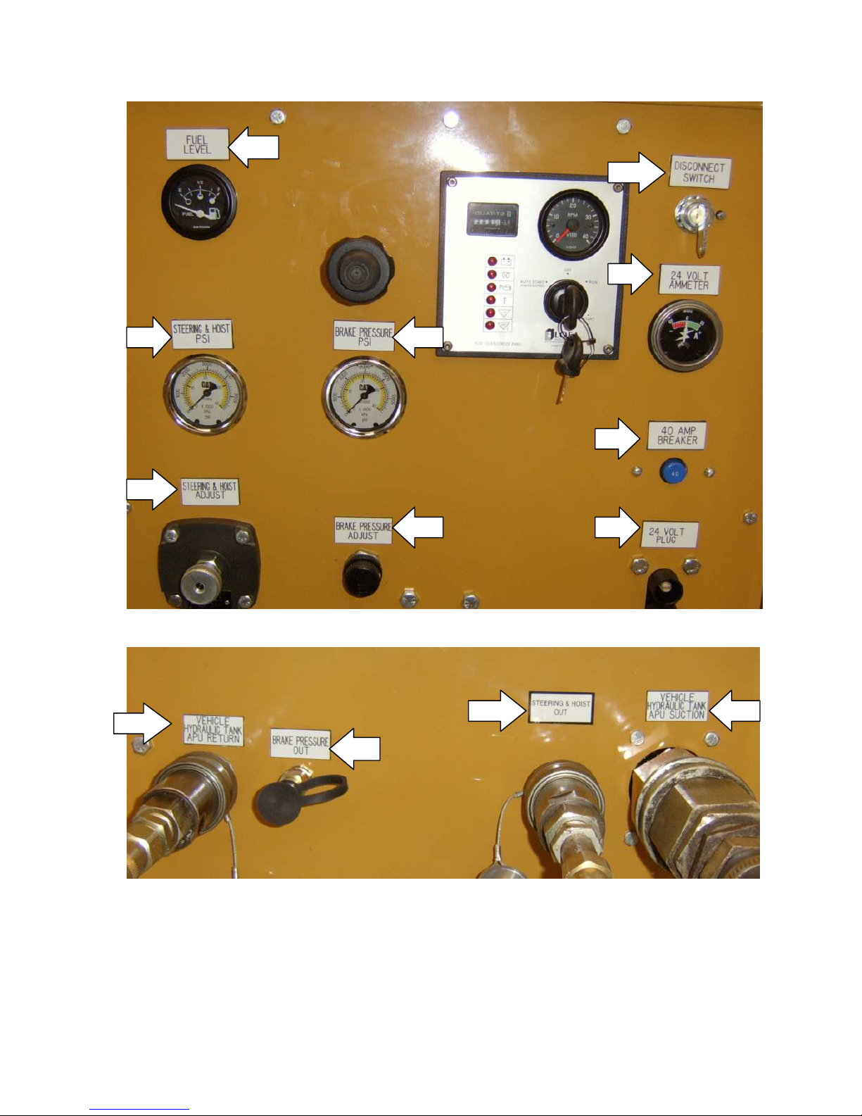
Brake Pressure PSI
(Fig 3.2B arrow A)
Steering & Hoist PSI
(Fig 3.2B arrow B)
Disconnect Switch
(Fig 3.2B arrow C)
Brake Pressure Adjust
(Fig 3.2B arrow D)
Steering & Hoist Adjust
(Fig 3.2B arrow E)
24 Volt Ammeter
(Fig 3.2B arrow F)
Refer to the engine owner’s manual for
explanation of controls and symbols
located on the engine.
The following decals are placed on the
power unit to aid in its operation and
maintenance. The operator should locate
and understand them before using this
power unit.
Clutch engagement
(Fig 3.2A)
Fig 3.2A
24 Volt Plug
(Fig 3.2B arrow G)
Fuel Level
(Fig 3.2B arrow H)
40 Amp Breaker
(Fig 3.2B arrow I)
Vehicle Hydraulic Tank APU Return
(Fig 3.2C arrow A)
Brake Pressure Out
(Fig 3.2C arrow B)
Steering & Hoist Out
(Fig 3.2C arrow C)
Vehicle Reservoir APU Suction
(Fig 3.2C arrow D)
Page 8
8
Fig 3.2B
ABEHIBC
D
Fig 3.2C
Page 9

9
3.3 Before Start Up
Check engine oil level, and engine air
filter. Refer to the engine manual for
proper procedures when checking, filing,
cleaning, or replace any engine
components and fluids.
Check the hydraulic oil reservoir level of
the disabled trucks. Follow the truck
manufactures recommendation for fluid
type.
Check that the fuel level is at an
adequate level before starting engine.
Check that fasteners and fittings are
tight, and tighten any fittings, which may
develop a leak or fasteners that may
become loose immediately. Hydraulic
hoses and couples should be inspected
for wear, cracking, or fatigue prior to
starting the engine.
The power unit is shipped without a
battery. A 12 Volt Battery is required for
starting the engine and operating the
electrical pump controls. A Group 24
Battery is used on the power unit.
The power unit features a Caterpillar
diesel engine and is shipped with a
Caterpillar operator’s manual. See the
engine manual for operating and
maintenance information concerning the
engine.
The engine is equipped with its own 12
Volt DC charging system and will
maintain the charge on the 12 Volt
battery in the power unit.
WARNING: NEVER INSPECT
PRESSUREIZED HOSES,
COUPLERS, OR FITTINGS WITH
HANDS OR AT CLOSE
DISTANCES. PRESSURIZE FLUID
CAN PUNCTURE THE SKIN AND
INJECT OIL INTO THE BODY
RESULTING IN DEATH.
Do not use hoses, couples, or fittings
which are damaged, replace
immediately.
See section 2.8 of this manual for
additional safety procedures.
3.4 Positioning the Power Unit
The power unit can be positioned by
using a crane. The power unit has lifting
eyes so it can be loaded easily or
positioned at the work sight with a crane.
(Fig 1.2A)
Place the PortaCo hydraulic Power Unit
on a level surface with no greater than a
20 degree slope to prevent fuel spillage
and power unit movement
WARNING: PLACING THE
PORTACO HYDRAULIC POWER
UNIT ON EXCESSIVE SLOPES OR
UNSTABLE PLATFORMS COULD
CAUSE THE UNIT TO ROLL OR
TIP DAMAGING THE POWER
UNIT OR ENDANGERING
WORKERS.
Locate hydraulic power unit in well lit
area with a minimum ambient light
intensity of 200 lux weather indoors or
outdoors, particularly at night. Keep the
power unit at least 1 meter (3.3ft) away
from buildings, obstructions, and
flammable objects. Do not aim engine
exhaust at materials that could catch fire.
3.5 Power Unit Operation
Page 10

10
Observe all safety precautions found
through out this manual and the included
engine manual.
1) Connect the hose and/or electrical
groups to the disabled truck following
the instructions provided with the group
being used. Connect all groups to the
truck before connecting to the PortaCo
power unit.
NOTE: Clean ends of couplers before
connecting to prevent system
contamination.
2) Make sure the pump engage lever is
in the “out” position and the disconnect
switch, located on the instrument panel,
is in the “off” position.
WARNING: Exhaust fumes can cause
personal injury or death. In an
enclosed are, vent the exhaust to the
outside. Start and operate the engine
in a well ventilated area only.
3) Start the engine.
4) When the engine is ready to use, pull
the throttle out all the way to run the
engine at maximum speed of 2600 rpm.
NOTICE: To prevent damage to the
hydraulic pump; do not adjust the
engine speed above 2600 rpm.
5) To activate the 24 volt circuit, turn the
disconnect switch to the “ON” position..
CAUTION: DO NOT ATTEMPT TO
CONNECT OR DISCONNECT THE
CORD WITH THE DISCONNECT
SWITCH ON. DOING SO COULD
TRIP THE BREAKER OR
DAMAGE THE ELECTRICAL
SYSTEM OF THE POWER UNIT
OR TRUCK.
6) To engage the hydraulic pump, move
the clutch engagement lever to the “in”
position. The pressure for the steering
and hoist circuit and breaking circuit can
be manually adjusted to meet the
operators requirements. The controls are
below the pressure gauge for each
system.
7) To shut down the power unit turn the
disconnect switch off and move the
clutch engagement lever to the “out”
position.
8) To stop the engine, return the throttle
to the idle position. Allow the engine to
run at idle for 3 to 4 minutes before
turning the ignition switch off.
3.7 Cold Weather Operation
Hydraulic fluids are thicker in cold
weather; therefore, run the engine at low
idle long enough to bring the fluid
temperature up to minimum of 10°C/50°
F or until the hydraulic tank feels warm.
Refer to the engine manual for cold
weather operating recommendations.
3.8 Storage Preparation
To prepare the engine for transportation
or storage refer to the engine owner's
manual. Remove the ground cable from
the battery.
Store the PortaCo hydraulic power unit
on a smooth level surface. The power
unit should be stored in a cool, dry
environment which is not subjected to
rapid temperature changes.
Page 11
11
4.0 Maintenance Instructions
Lube Data
Engine Lube: See the engine manual provided for service requirements and
procedures.
Hydraulic System:
- Once a month check the hydraulic hoses and fittings for damage. Replace
components as required.
- Once a month check the pump coupling for damage. Replace as required.
- Once a month check the voltage of the battery service as required
following the battery manufactures recommendations.
- Annually clean the hydraulic system strainer located inline behind the
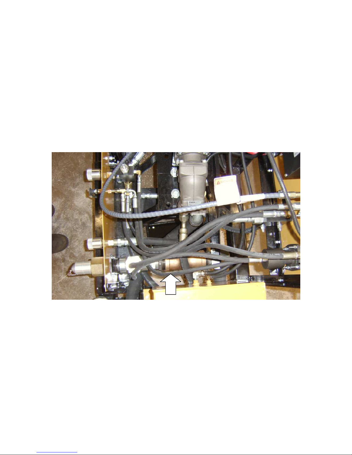
“APU Suction” coupler. (See Figure #88 in parts view)(Fig 4.0A arrow A)
A
Fig. 4.0A
Page 12

12
CAUTION: USE ONLY GENUINE PORTACO INC PARTS OR EQUIVALENT.
THE USE OF REPLACEMENT PARTS WHICH ARE NOT OF EQUIVALENT
QUALITY MAY DAMAGE THE HYDRAULIC POWER UNIT.
WARNING: UNAUTHORIZED MODIFICATIONS TO THE POWER UNIT
MAY IMPAIR THE FUNCTION AND/OR SAFETY AND IMPAIR MACHINE
LIFE. USE ONLY APPROVED SERVICE PARTS OR ACCESSORIES.
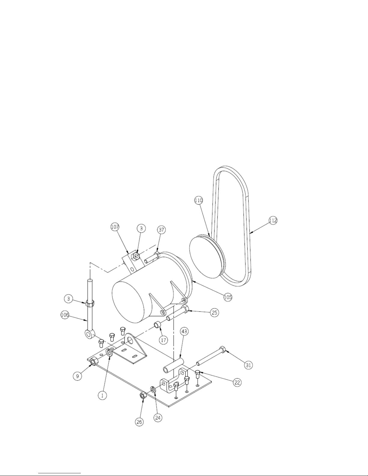
4.1 Assembly View and Parts List
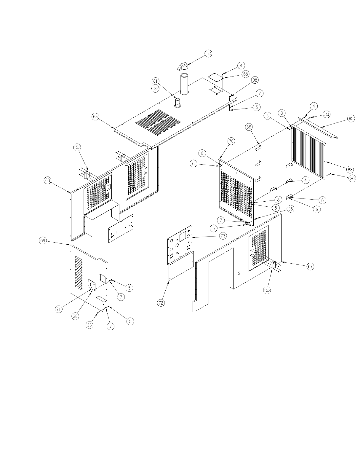
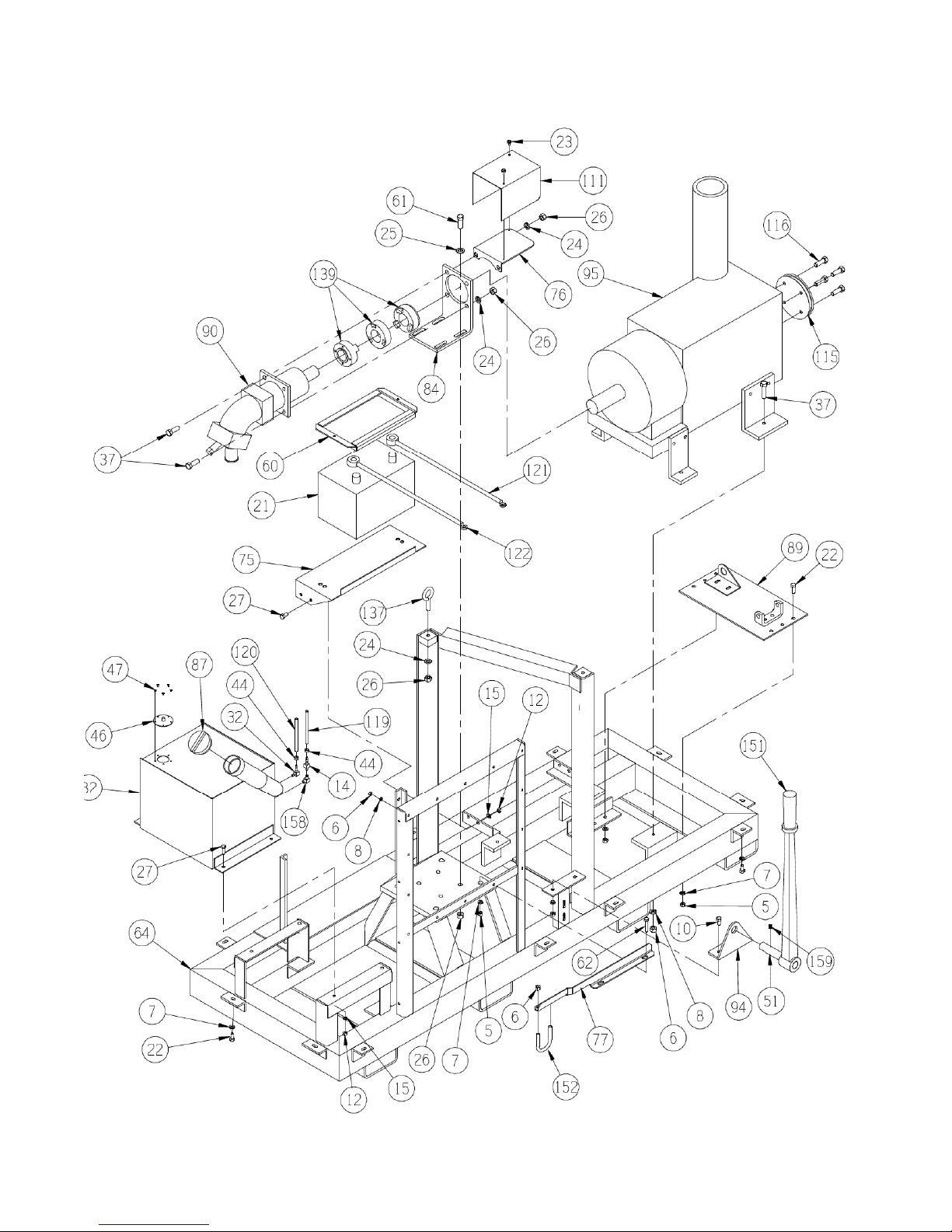
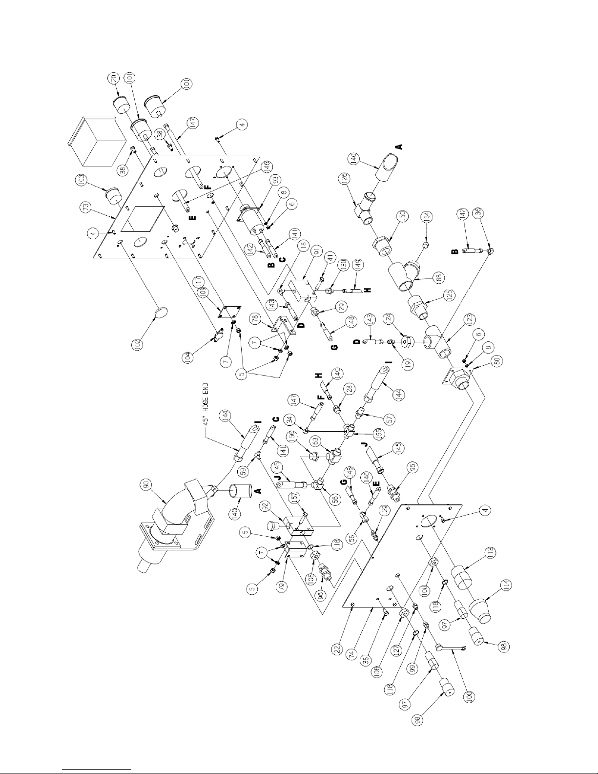
ITEM NO. PART NO. DESCRIPTION QTY
1 4286-OOP WASHER LOCK 5/8 1
2 1040-OOP BOLT #10 – 32 2
3 3017-OOP NUT 5/8NC 2
4 1044-OOP BOLT ¼ nc x ¾ HH PL #5 35
5 1061-OOP NUT 3/8 nc 36
6 1062-OOP NUT ¼ nc 49
7 1063-OOP LOCK WASHER 3/8 45
8 1064-OOP LOCK WASHER ¼ 43
9 3125-OOP NUT NYLOCK 5/8 NC 1
10 1078-OOP BOLT 3/8 nc x 1 ½ 2
11 1093-OOP FLAT WASHER 3/8 2
12 1094-OOP NUT 5/16 10
14 4987-OOP FITTING BRASS STEM 1
15 1175-OOP LOCK WASHER 5/16 10
16 1176-OOP FLAT WASHER 5/16 12
17 5185-OOD SPACER .75 OD X .625 ID X .50 LONG 1
18 1237-OOP FITTING 6-6 1
19 1238-OOP FITTING 6-6 1
20 1281-OOP FUEL GAUGE 1
21 1301-OOP BATTERY 1
22 1324-OOP BOLT, 3/8 nc x 1 HH PL #5 19
23 1621-OOP SCREW 2
24 1349-OOP LOCK WASHER ½ 19
25 4618-OOP BOLT 5/8 NC X 3.00 1
26 1351-OOP NUT ½ NC HH PL 13
27 1366-OOP BOLT 5/16 x 1 8
28 1401-OOP FITTING 8-12 T 1
29 1404-OOP FITTING 8-12 1
Page 13

13
30 1414-OOP BOLT ¼ nc x 1 ¼ 10
31 1553-OOP BOLT ½ nc x 6 1
32 1662-OOP FITTING -4 90° 1
33 1625-OOP LOCK WASHER 10 – 32 2
34 1788-OOP FITTING 4-4 1
36 1250-OOP CLAMP 1
37 1872-OOP BOLT ½ nc x 2 9
38 1932-OOP BOLT 3/8 nc x ¾ HH PL #5 24
39 5072-OOP CLAMP 2
40 2301-OOP WIRE TIE 3
41 1989-OOP BOLT 3/8 nc x 2 ½ HH PL #5 2
42 1350-OOP WASHER ½ FLAT 6
43 1997-OOD SPACER BRACKET ALT. 1
44 2036-OOP HOSE CLAMP 3
45 1042-OOP BOLT 3/8 NC X 1.75 2
46 2076-OOP FUEL SENDER 1
47 2077-OOP SCREW SELF TAP #10 x 5/8 SLT- HX 5
50 5197-OOP O-RING 4000-12 1
51 5190-OOW SHAFT SPLINED 1
54 5189-OOP HOSE CLAMP T-BOLT 2
55 1099-OOP WASHER FLAT 1/4 2
56 3458-OOP FITTING 12-12 45° 1
57 3459-OOP FITTING 12-12 1
58 3578-OOP FITTING 6-6-6 1
59 3741-OOP FITTING 1
60 1302-OOW BATTERY HOLD DOWN 1
61 4433-OOP BOLT ½ NC X 2.75 4
62 3603-OOP BOLT 3/8 X 2.75 2
63 4603-OOP FITTING 12-12-12 1
64 5113-OOW FRAME 1
65 5114-OOW TOP PANEL 1
66 5115-OOD RADIATOR ACCESS COVER 1
67 5116-OOW FRONT PANEL 1
68 5117-OOW BACK PANEL 1
69 5118-OOW LEFT END 1
70 5119-OOW RIGHT END 1
71 5120-OOD COVER FILL TUBE 1
Page 14

14
72 5121-OOD PANEL F2 1
73 5122-OOD GAUGE PANEL 1
74 5123-OOD PANEL – QD CONNECTION 1
75 5124-OOD BASE PLATE 1
76 5125-OOD PUMP GUARD 1
77 5126-OOD MANIFOLD SUPPORT 1
78 5127-OOD MANIFOLD MTG. BRACKET 1
79 5128-OOD MANIFOLD MTG. BRACKET 1
80 5129-OOW PLATE 1
81 5130-OOD TUBE AIR INTAKE 1
82 5131-OOW FUEL TANK 1
83 5132-OOW GRILL 1
84 5133-OOD PUMP MOUNT 1
85 5134-OOD SHROUD COVER 1
86 5135-OOD STAND-OFF 7
87 5137-OOP FUEL CAP 1
88 5138-OOP MUELLER STRAINER 1
89 5136-OOW ALTERNATOR PLATE 1
90 5139-OOP PUMP 1
91 5140-OOP VALVE 1
92 5141-OOP VALVE 1
93 5142-OOP VALVE 1
94 5143-OOP BALL BEARING 1” SHAFT 1
95 5144-OOP ENGINE 1
96 5145-OOP UNION 2
97 1591-OOP NIPPLE 2
98 1592-OOP CAP 2
99 1799-OOP NIPPLE 1
100 1800-OOP CAP 1
101 1574-OOP GAGE 2
102 1584-OOP SWITCH 1
103 1579-OOP AMMETER 1
104 1583-OOP BREAKER 1
105 1550-OOP ALTERNATOR 1
106 5146-OOP ROD 1
107 5147-OOP BLOCK 1
108 5148-OOP NUT 3
Page 15

15
109 1580-OOP RECEPTACLE 1
110 1551-OOP PULLEY 1
111 5223-OOD GUARD COUPLER 1
112 5151-OOP BELT 1
113 5152-OOP PLUG 1
114 5153-OOP DUST CAP 1
115 5154-OOP PULLEY-PTO 1
116 5155-OOP 12mm – 1.75 x 35 8.8 HCS 4
117 1581-OOP CAP ELECTICAL PLUG 1
118 5156-OOP O-RINGS 4
119 5157-OOP 3/16” FUEL LINE 65” 1
120 5158-OOP 1/4” FUEL LINE 72” 1
121 1204-OOP POSITIVE CABLE 1
122 1205-OOP NEGATIVE CABLE 1
123 5160-OOP FITTING 24-24-24 T 1
124 5161-OOP FITTING 24-PLUG 1
125 5162-OOP FITTING 24-32 BUSHING 2
126 2597-OOP FITTING 24-24 BEADED 1
127 5163-OOP FITTING 4-6 1
128 5164-OOP BULKHEAD NUT 1
129 4324-OOP BULKHEAD FITTING 1
130 5165-OOP FITTING 12-8 1
132 5166-OOP 1 ¾” EXHAUST CLAMP 5/16 1
133 5167-OOP 3 ¾” EXHAUST CLAMP 5/16 1
134 3247-OOP EXHAUST RAIN CAP 1
136 2479-OOP FITTING 90° 1
137 5169-OOP LIFT EYE BOLTS 2
139 5170-OOP PUMP COUPLER 1
140 5171-OOP 1 ½ SUCTION HOSE 53” 1
141 5172-OOP A x 4-HOSE 4-4MP-4-4FJ 29.5” 1
142 5173-OOP A x 4-HOSE 4-4MP-4-4FJ 22” 1
143 5174-OOP A x 6-HOSE 6-6FJ 22.5” 1
144 5175-OOP B x 12-HOSE 12-12FJ 36” (4000 PSI) 1
145 5176-OOP B x 12-HOSE 12-12FJ 40” (4000 PSI) 1
146 5177-OOP A x 4-HOSE 4-6FJ-4-4FF 32” 1
147 5178-OOP A x 4-HOSE 4-4FF-4-4JF 33” 1
148 5179-OOP A x 6 -HOSE 6-6FJ-6-8MP 27” 1
Page 16
16
149 5159-OOP AM08-HOSE 8-8FJ-8-8FF 27.5” 1
150 5186-OOP BUSHING 32-24 1
151 5181-OOP PTO – LEVER EXT. 1
152 5182-OOP U-BOLT 1
153 5183-OOP LATCH 3
WEATHER STRIP 220” 1
154 5187-OOP PIPE PLUG 1”NPT 1
155 1382-OOP FITTING TEE 1
156 5192-OOP FITTING 6401-12-12 1
157 5188-OOP BOLT 3/8 NC X 2.25 2
158 1851-OOP FITTING -2-2 STR 1
159 2352-OOP SET SCREW 3/8 NC X 5/8 ALLEN HEAD 1
Page 17
17
Page 18
1
8
Page 19
19
Page 20

20
4.2 Hydraulic Fluid and Engine
Maintenance
WARNING: SHUT OFF ENGINE
BEFORE DOING ANY
MAINTENANCE. TO PREVENT
ACCIDENTAL START-UP, TURN
THE IGNITION SWITCH OFF AND
DISCONNECT THE NEGATIVE
CABLE FROM THE BATTERY
TERMINAL.
Engine Lubrication Servicing
Check the engine oil level. The oil level
should be between the “full” and “add”
marks of the dipstick.
When draining oil place a suitable
container under the drain plug and
remove plug. Drain engine completely
and replace plug.
When replacing engine oil filter, place a
suitable container under the filter and
remove filter. Apply a film of clean oil
to the gasket surface of the new filter.
Install new filter element and tighten
one-half turn after initial gasket contact.
NOTE: Dispose of all consumable items
(filters, oils….etc.) in a manner that is
compatible with the environment.
PortaCo, Inc. suggests you take such
items in a sealed container to your local
service station for reclamation. DO
NOT throw these items in the trash or
pour them on the ground.
Hydraulic Fluid Servicing
See engine manual for detailed
instructions and service intervals.
Page 21

21
4.3 Trouble Shooting
PROBLEM CAUSE REMEDY
Starter will not crank engine
Engine working against the
hydraulic pump pressure.
Battery discharged or not
properly connected.
Be sure Circuit Switches are
OFF.
Check condition of battery,
cable connections, etc.
Replace as necessary.
Starter defective. Inspect starter. Replace as
necessary.
Ignition switch or solenoid
Replace as necessary.
switche(es) defective.
Engine cranks but will not
start
Air in injectors and/or
injector pump.
Bleed injectors. Refer to
engine manual.
Water in fuel. Empty water sediment trap.
Bleed injectors per engine
manual.
Cold start not functioning. Check current to glow plugs
on cold start units. Repair
circuit or replace glow plug
as required.
Inadequate compression. Check for clogged air
cleaner, valves seated,
cylinder compression loss.
Repair as required.
Engine runs but hydraulic
circuit will not operate truck
functions
Circuit switches off or
defective.
Hydraulic fluid reservoir
Set switches to on. Replace
if defective.
Check and fill as required.
low
Hoses incorrectly connected
to power unit or truck.
Check that the hose group
installation is correct.
Page 22

22
SERVICE AND REPAIR NOTES
 Loading...