

Page 1
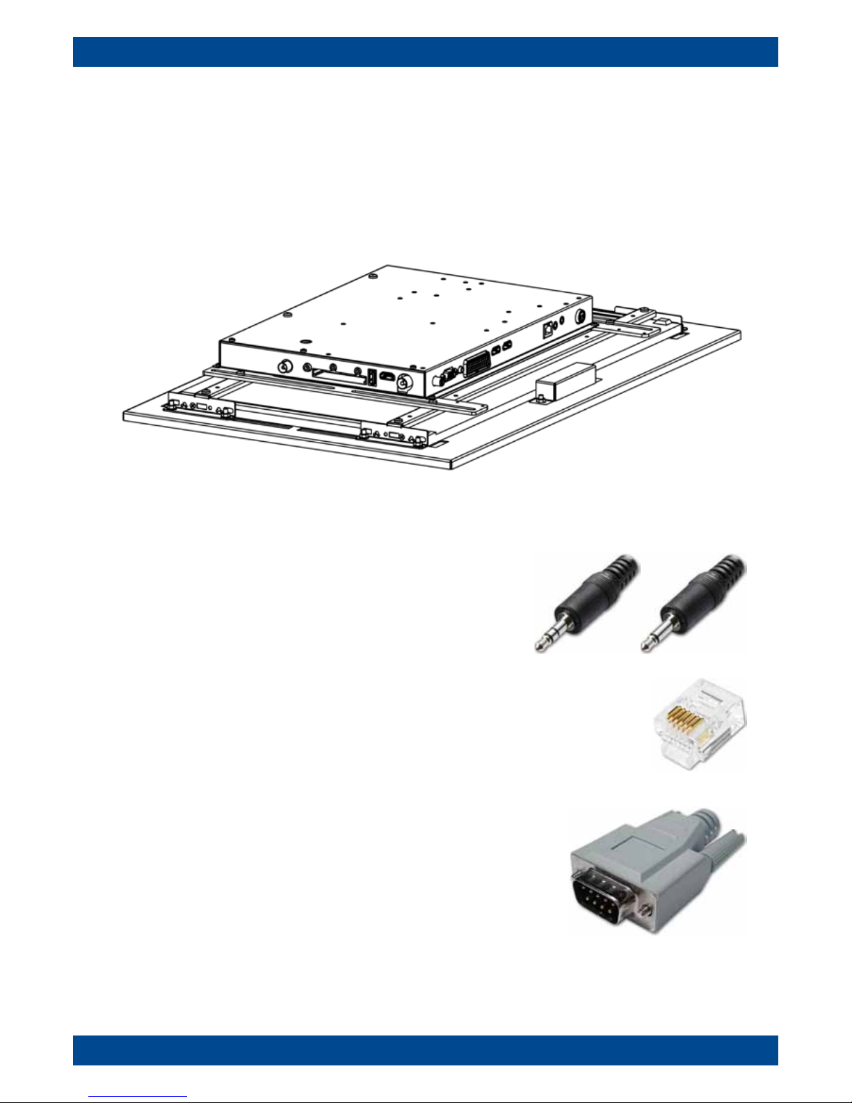
TileVision® Interface Connections
and Control Codes
TV/22/FR2
IR Link Out & In
These enable control of external equipment via the IR sensor on
the TileVision® and control of the TileVision® from a remote location.
RJ12 Connector
This connector allows the TileVision® to be integrated with Interactive Hotel TV Systems.
RS-232 Port
This DB9 connector allows the TileVision® to receive command codes from
Home Automation Systems.
Page 2
1
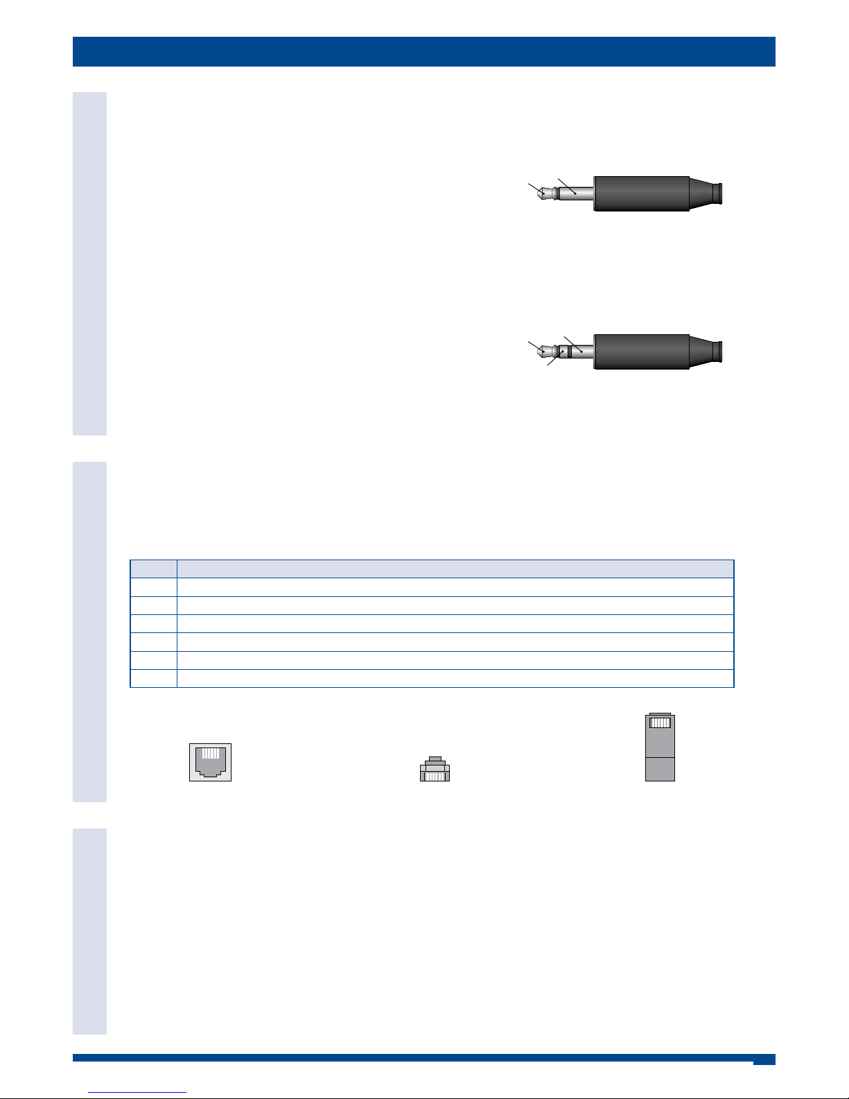
IR Link Out
The IR Link Out is a 3.5mm mono jack socket. The IR signal sensed by the TileVision® is outputted from this socket to an
IR emitter. This will enable the remote control of external equipment, such as a DVD player, from the TileVision®.
IR Link Out Connections – IR Emitter
IR emitter LED positive terminal to the Tip.
IR emitter LED negative terminal to the Sleeve.
IR Link In
The IR Link In is a 3.5mm stereo jack socket. This socket allows an auxiliary IR sensor to be connected to the TileVision®
to enable remote control of the TileVision® from a different point other than the front of the TileVision®.
IR Link In Connections – IR Receiver
The TileVision® interface will supply +5v DC to power the IR sensor.
IR sensor +5v DC terminal to the Tip.
IR sensor signal output terminal to the Ring.
IR sensor negative terminal to the Sleeve.
3.5 mm mono jack plug
Tip
Sleeve
Ring
3.5 mm stereo jack plug
Tip
Sleeve
RJ12 Connector
This connector is for Hotel TV System Integration. The RJ12 allows command codes to pass to and from the TileVision®.
The RJ12 pin assignment is internally configurable, to allow the connection of various Hotel TV Systems.
RJ12 Connector – Standard Configuration
Pin No Function
1 Not Connected
2 Command code from the external equipment to the TileVision® (0V/5V nominal)
3 Not Connected
4 TileVision® On signal from the TileVision® to the external equipment (On = 5V, Standby = 0V nominal)
5 0V – DC ground
6 Demodulated IR signal from the TileVision® IR sensor to the external equipment (0v/5v nominal)
Connector on the Interface PCB
1 6
Male RJ12 connector – front view
1 6
Male RJ12 connector – top view
1 6
IR Links RJ12 Connections
IR Remote Control
The IR remote control uses the NEC protocol.
For a full listing of the IR remote control codes refer to page 4.
IR Remote Control
TileVision® Interface Connections
IR Links and RJ12 Connections
Page 3
2
Command Codes via the RJ12 Connector
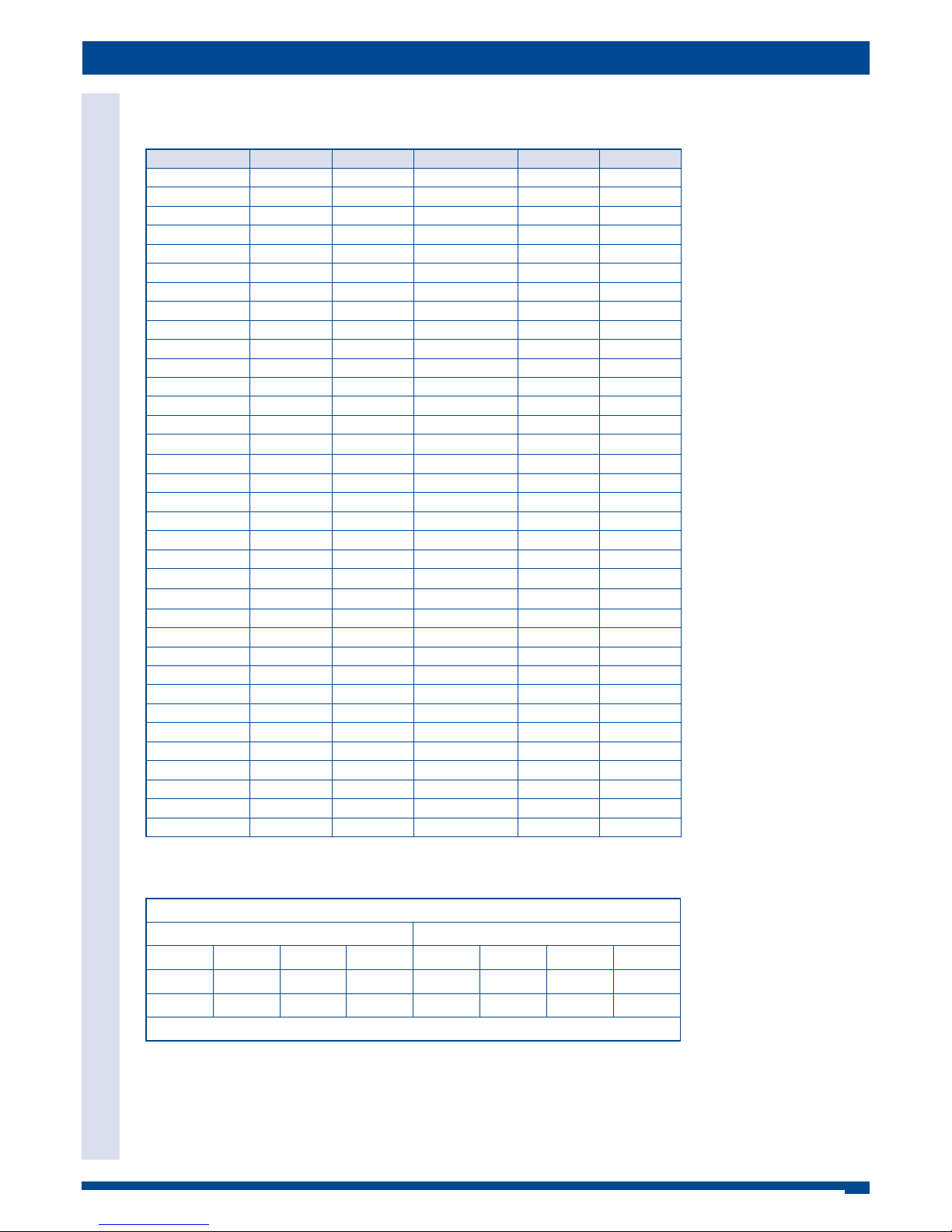
The codes in the table below are the codes that will be sent to the TileVision via the RJ12 connector.
The voltage levels that are accepted as an input on pin 2 of the RJ12 connector (command code from external
equipment to the TileVision®) are:
HIGH + 5 volts DC LOW 0 volts DC
Important: When the input on pin 2 of the RJ12 connector is inactive/idle it must be held HIGH. If pin 2 of the RJ12
connector is held low, all subsequent command codes via the RJ12 connector and via the TileVision® IR receiver (sent
from the TileVision® IR remote control) will fail and the TileVision® will be non responsive.
Pin 5 of the RJ12 connector is DC ground.
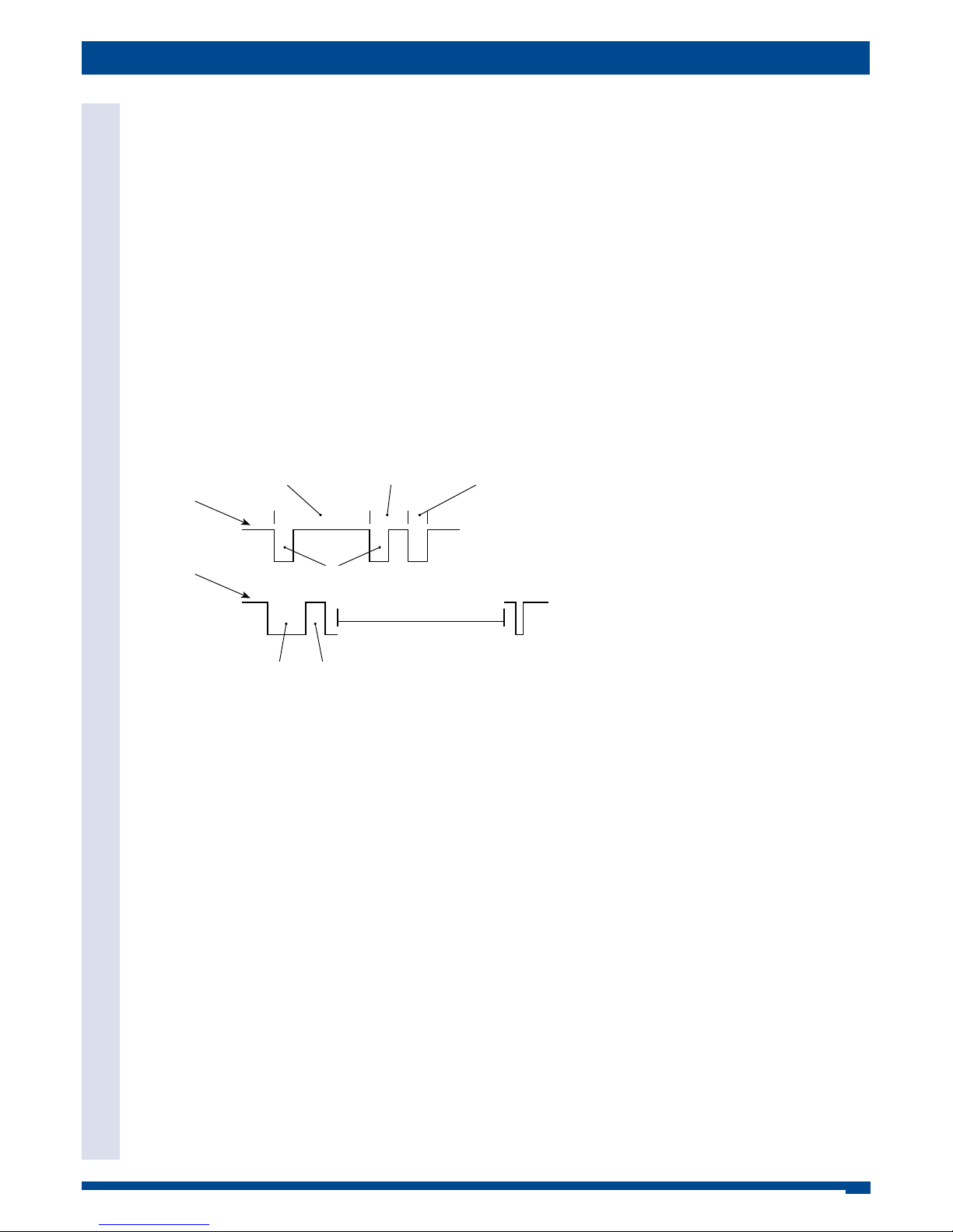
The code sequence sent to the RJ12 connector is a DEMODULATED NEC protocol format.
First Start Pulse LOW 9.0 ms. Second Start Pulse HIGH 4.5 ms.
Logic 1 = LOW 560 µs HIGH 1.69 ms. Logic 0 = LOW 560 µs HIGH 560 µs.
Stop Pulse LOW 560 µs.
TileVision® Interface Connections
RJ12 Command Code Format
RJ12 Command Code Format
Logic 1 – 2.25 ms
Inactive/idle
HIGH
Inactive/idle
HIGH
Logic 0 – 1.12 ms
Address
0 2 F D
Code
E A 1 5
Stop 560 µs
9 ms 4.5 ms
560 µs
Page 4
3
TileVision® Interface Connections
RJ12 Command Codes – Address 02
FD
RJ12 Command Codes – Address 02FD
RJ 12 Connector Code Listing (Hex) Address 02FD
Function Code Check Sum Function Code Check Sum
Power ON EA 15 INFO 05 FA
Power OFF FA 05 Zoom 15 EA
Power TOGGLE B0 4F Mute 41 BE
Source 10 EF P. Mode B4 4B
DTV 9E 61 S. Mode B5 4A
ATV 8E 71 Sleep 35 CA
AV DE 21 FAV 01 FE
SCART EB 14 PVR List 75 8A
Component 7E 81
9
74 8B
PC-RGB AE 51
31 CE
HDMI 1 CE 31
g
21 DE
HDMI 2 1B E4 Rec / Home 84 7B
HDMI 3 0B F4
7
F4 0B
Media Player 8C 73
8
D4 2B
0 65 9A
4/;
61 9E
1 24 DB Exit B1 4E
2 34 CB Timeshift E0 1F
3 F0 0F Menu E4 1B
4 E1 1E Back 90 6F
5 D1 2E EPG 51 AE
6 C1 3E SUB. T 44 BB
7 81 7E Audio 11 EE
8 54 AB TTX / Mix 95 6A
9 C4 3B Index 80 7F
Volume Up A0 5F Reveal 94 6B
Volume Down 04 FB Cancel 70 8F
Channel Up 55 AA Hold A1 5E
Channel Down A5 5A Size F5 0A
Page Up 60 9F List 40 BF
Page Down 85 7A RED 64 9B
Left C0 3F GREEN A4 5B
Right 50 AF YELLOW 25 DA
OK 20 DF BLUE E5 1A
Up 71 8E
Down D0 2F
The above codes are sent LEAST significant bit first.
Least Significant Bit first - 0 2 F D 0 4 F B
Address Code & Check Sum
0 2 F D 0 4 F B
0000 0100 1111 1011 0000 0010 1111 1101
1248 1248 1248 1248 1248 1248 1248 1248
LSB Weighting MSB
Page 5
4
TileVision® Interface Connections
IR Remote Control Codes – NEC Protocol – Address 20
DF
IR Remote Control Codes – NEC Protocol – Address 20DF
To program an IR remote control to transmit an IR signal to operate the TileVision, the codes in the table below must be
entered.
IR Code Listing (Hex) Address 20DF
Function Code Check Sum Function Code Check Sum
Power ON AE 51 INFO 50 AF
Power OFF AF 50 Zoom 51 AE
Power TOGGLE 0B F4 Mute 14 EB
Source 01 FE P. Mode 4B B4
DTV E9 16 S. Mode 5B A4
ATV E8 17 Sleep 53 AC
AV ED 12 FAV 10 EF
SCART EB 14 PVR List 57 A8
Component E7 18
9
47 B8
PC-RGB EA 15
13 EC
HDMI 1 EC 13
g
12 ED
HDMI 2 B1 4E Rec / Home 48 B7
HDMI 3 B0 4F
7
4F B0
Media Player C8 37
8
4D B2
0 56 A9
4/;
16 E9
1 42 BD Exit 1B E4
2 43 BC Timeshift 0E F1
3 0F F0 Menu 4E B1
4 1E E1 Back 09 F6
5 1D E2 EPG 15 EA
6 1C E3 SUB. T 44 BB
7 18 E7 Audio 11 EE
8 45 BA TTX / Mix 59 A6
9 4C B3 Index 08 F7
Volume Up 0A F5 Reveal 49 B6
Volume Down 40 BF Cancel 07 F8
Channel Up 55 AA Hold 1A E5
Channel Down 5A A5 Size 5F A0
Page Up 06 F9 List 04 FB
Page Down 58 A7 RED 46 B9
Left 0C F3 GREEN 4A B5
Right 05 FA YELLOW 52 AD
OK 02 FD BLUE 5E A1
Up 17 E8
Down 0D F2
Page 6
5
TileVision® Interface Connections
The RS-232 Port
The RS-232 Port
RS-232 Port
The RS-232 port is a DB9 male connector. This connector allows Home Automation Systems to send command codes
directly to the TileVision®.
The TileVision® will only receive RS-232 codes, it does not transmit codes.
To connect to the RS-232 port a DB9 MALE connector must be used.
RS-232 Protocol
Baud Rate: 38400
Bits: 8
Parity: None
Stop Bit: 1
Command Code Sequence
A0 F0 55 FF <IR Code> <Check Sum>
The time of the command sequence must be <500 ms.
The interval time of two continuous command sequences must be >500 ms.
RS 232 Code Listing (Hex)
Function Code Check Sum Function Code Check Sum
Power ON AE 51 INFO 50 AF
Power OFF AF 50 Zoom 51 AE
Power TOGGLE 0B F4 Mute 14 EB
Source 01 FE P. Mode 4B B4
DTV E9 16 S. Mode 5B A4
ATV E8 17 Sleep 53 AC
AV ED 12 FAV 10 EF
SCART EB 14 PVR List 57 A8
Component E7 18
9
47 B8
PC-RGB EA 15
13 EC
HDMI 1 EC 13
g
12 ED
HDMI 2 B1 4E Rec / Home 48 B7
HDMI 3 B0 4F
7
4F B0
Media Player C8 37
8
4D B2
0 56 A9
4/;
16 E9
1 42 BD Exit 1B E4
2 43 BC Timeshift 0E F1
3 0F F0 Menu 4E B1
4 1E E1 Back 09 F6
5 1D E2 EPG 15 EA
6 1C E3 SUB. T 44 BB
7 18 E7 Audio 11 EE
8 45 BA TTX / Mix 59 A6
9 4C B3 Index 08 F7
Volume Up 0A F5 Reveal 49 B6
Volume Down 40 BF Cancel 07 F8
Channel Up 55 AA Hold 1A E5
Channel Down 5A A5 Size 5F A0
Page Up 06 F9 List 04 FB
Page Down 58 A7 RED 46 B9
Left 0C F3 GREEN 4A B5
Right 05 FA YELLOW 52 AD
OK 02 FD BLUE 5E A1
Up 17 E8
Down 0D F2
Page 7

Porter Lancastrian Limited
Lower Healey Business Park · Froom Street · Chorley · Lancashire · UK · PR6 9AR
Tel: 0870 871 0111 · Fax: 0870 871 0112
Sales: [email protected] · Web: www.tilevision.tv
Control Codes 04/14
 Loading...