

Page 1
Technical Manual
-.8e;~~
Technical Information
Contents:
Group 9
Electrics
WKD 483 521
Page 2
Boxster
Foreword
Foreword
The workshop documentation for the Boxster model has the designation "Boxster" Technical Manual
and contains Technical Information as well as instructions on Repairs.
The integration of the technical information published in the "Boxster" Technical Manual with the
descriptive matter on repairs provides the user with a complex reference work that combines into one
book associated or cross-referenced material of relevance to workshops and originating from various
information media.
The "Boxster" Technical Manual consists of 15 folders, subdivided into the following Groups
0 Entire vehicle -General
0 Diagnosis, part 1 (up to Repair Group 45) *1
0 Diagnosis, part 2 (as of Repair Group 69) *2
1 Engine, part 1 (up to Repair Group 13) *3
1 Engine, part 2 (as of Repair Group 15) *4
2 Fuel, exhaust, engine electronics
3 Transmission, manual transmission
3 Transmission, automatic transmission
4 Running gear
5 Body
6 Body equipment, exterior
7 Body equipment, interior
8 / 9 Air conditioning / Electrics
9 Circuit diagrams, part 1 (up to and including the '99 model) *5
9 Circuit diagrams, part 2 (as of the '00 model) *6
.1
The two folders with Group 0 are to be regarded as one folder; i.e. file the "Technical Information"
notices only in front of the repair descriptions in the folder "Group 0 -Diagnosis, part I"
(up to Repair Group 45).
*2
The second folder "Group 0 -Diagnosis, part 2" (as of Repair Group 69) includes the further
Repair Groups belonging to Group O.
.3
The two folders with Group 1 are to be regarded as one folder; i.e. file the "Technical Information"
notices only in front of the repair descriptions in the folder "Group 1 -Engine, part 1" (up to
Repair Group 13).
*4
The second folder "Group 1 -Engine, part 2" (as of Repair Group 15) includes the further Repair
Groups belonging to Group 1.
Foreword
Printed in Germany -34, October 1999
VORW.CHP
Page 3
Foreword
.!i
The two folders with Group 9 are to be regarded as one folder; i.e. file the "Technical Information"
Boxster
notices only in front of the repair descriptions in the folder "Group 9 -Circuit diagrams, part 1" (up to
the '99 model).
*Ei
The second folder "Group 9 -Circuit diagrams, part 2" (as of the '00 model) includes the further
circuit diagrams belonging to Group 9.
The "Boxster" Technical Manual has the same structure in each folder, with the following breakdown for
all Groups:
Title page, "Boxster" Technical Manual
> Foreword
Title page: "Technical Information"
> Table of Contents, Technical information
> Technical information
Title page: "Repair"
> Repair Groups: overview
> Table of Contents, repairs
> General/technical data
> Instructions on repairs
As can be seen from the breakdown, the published Technical Information is in the front part of each
folder -numbered according to the Groups. The Table of Contents assigned to each Group will be
periodically updated.
Following the Technical Information, separated by a title page, the instructions on repairs -assigned
according to the Groups or broken down into Repair Groups -are included in the folder.
The instructions on repairs will be extended and updated by means of supplements.
Note
Sheets that already exist in the "Boxster" Technical Manual and are updated or revised and thereby
exchanged by a supplement are designated "Replacement sheet". Revisions or technical modifications on
pages of these replacement sheets are identified for the user with a vertical bar at the margin.
VORW.CHP
Foreword
Printed in Germany -34, October 1999
Page 4
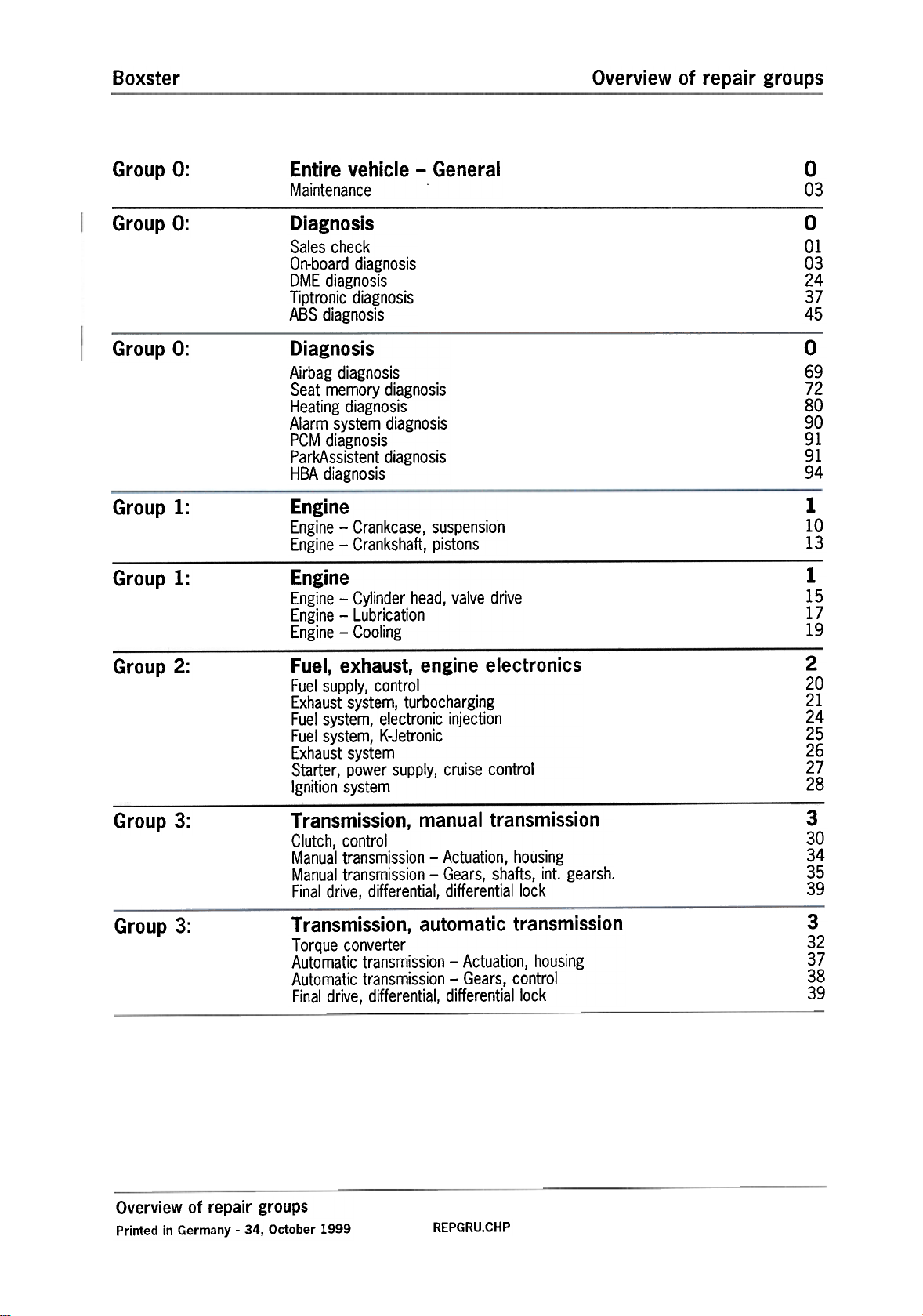
Overview of repair groupsBoxster
Group 0: Entire vehicle -General
Maintenance
Group 0:
Group 0:
Group 1:
Group 1:
Diagnosis
Sales check
On-board diagnosis
DME diagnosis
Tiptronic diagnosis
ABS diagnosis
Diagnosis
Airbag diagnosis
Seat memory diagnosis
Heating diagnosis
Alarm system diagnosis
PCM diagnosis
ParkAssistent diagnosis
HBA diagnosis
Engine
Engine -Crankcase, suspension
Engine -Crankshaft, pistons
Engine
Engine -Cylinder head, valve drive
Engine -Lubrication
Engine -Cooling
0
03
0
01
03
24
37
45
0
69
72
80
90
91
91
94
1
10
13
1
15
17
19
Group 2:
Group 3:
Group 3:
Fuel, exhaust, engine electronics
Fuel supply, control
Exhaust system, turbocharging
Fuel system, electronic injection
Fuel system, K-Jetronic
Exhaust system
Starter, power supply, cruise control
Ignition system
Transmission, manual transmission
Clutch, control
Manual transmission -Actuation, housing
Manual transmission -Gears, shafts, into gearsh.
Final drive, differential, differential lock
Transmission, automatic transmission
Torque converter
Automatic transmission -Actuation, housing
Automatic transmission -Gears, control
Final drive, differential, differential lock
2
20
21
24
25
26
27
28
3
30
34
35
39
3
32
37
38
39
Overview of repair groups
Printed in Germany -34, October 1999
REPGRU.CHP
Page 5
Overview of repair groups
Boxster
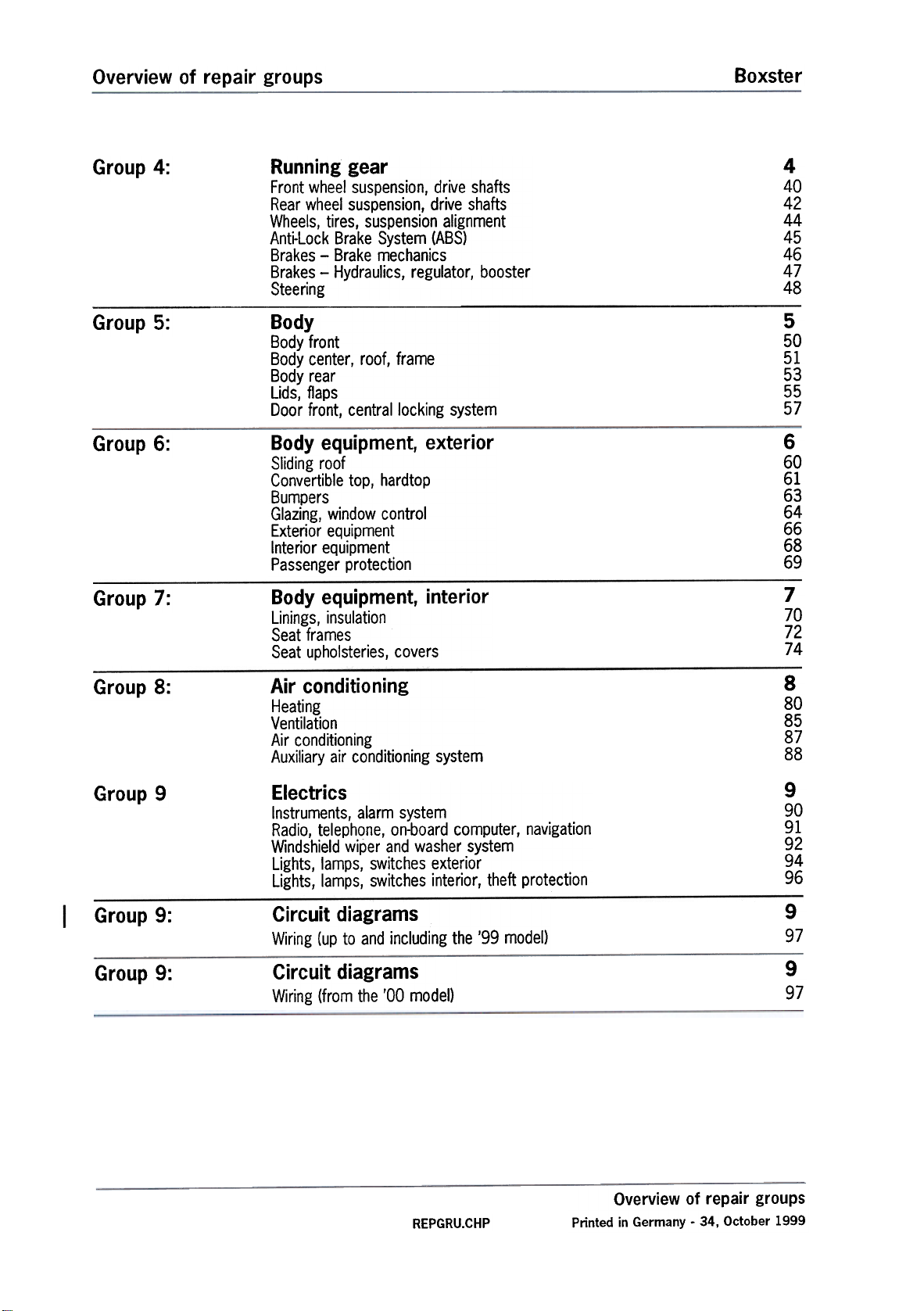
Group 4:
Group 5:
Group 6:
Group 7:
Running gear
Front whee! suspension, drive shafts
Rear wheel suspension, drive shafts
Wheels, tires, suspension alignment
Anti-Lock Brake System (ABS)
Brakes -Brake mechanics
Brakes -Hydraulics, regulator, booster
Steering
Body
Body front
Body center, roof, frame
Body rear
Lids, flaps
Door front, central locking system
Body equipment, exterior
Sliding roof
Convertible top, hardtop
Bumpers
Glazing, window control
Exterior equipment
Interior equipment
Passenger protection
Body equipment, interior
Linings, insulation
Seat frames
Seat upholsteries, covers
4
40
42
44
45
46
47
48
5
50
51
53
55
57
6
60
61
63
64
66
68
69
7
70
72
74
Group 8:
Group 9
Group 9:
Group 9:
Air conditioning
Heating
Ventilation
Air conditioning
Auxiliary air conditioning system
Electrics
Instruments, alarm system
Radio, telephone, on-board computer, navigation
Windshield wiper and washer system
Lights, lamps, switches exterior
Lights, lamps, switches interior, theft protection
Circuit diagrams
Wiring (up to and including the '99 model)
Circuit diagrams
Wiring (from the '00 model)
8
80
85
87
88
9
90
91
92
94
96
9
97
9
97
REPGRU.CHP
Overview of repair groups
Printed in Germany -34, October 1999
Page 6
Boxster
Table of Contents
8
8
8
80
8023 19
85
85
10
19
15
85
85
85
85
85
87
11
30
78
10
19
06
19
19
19
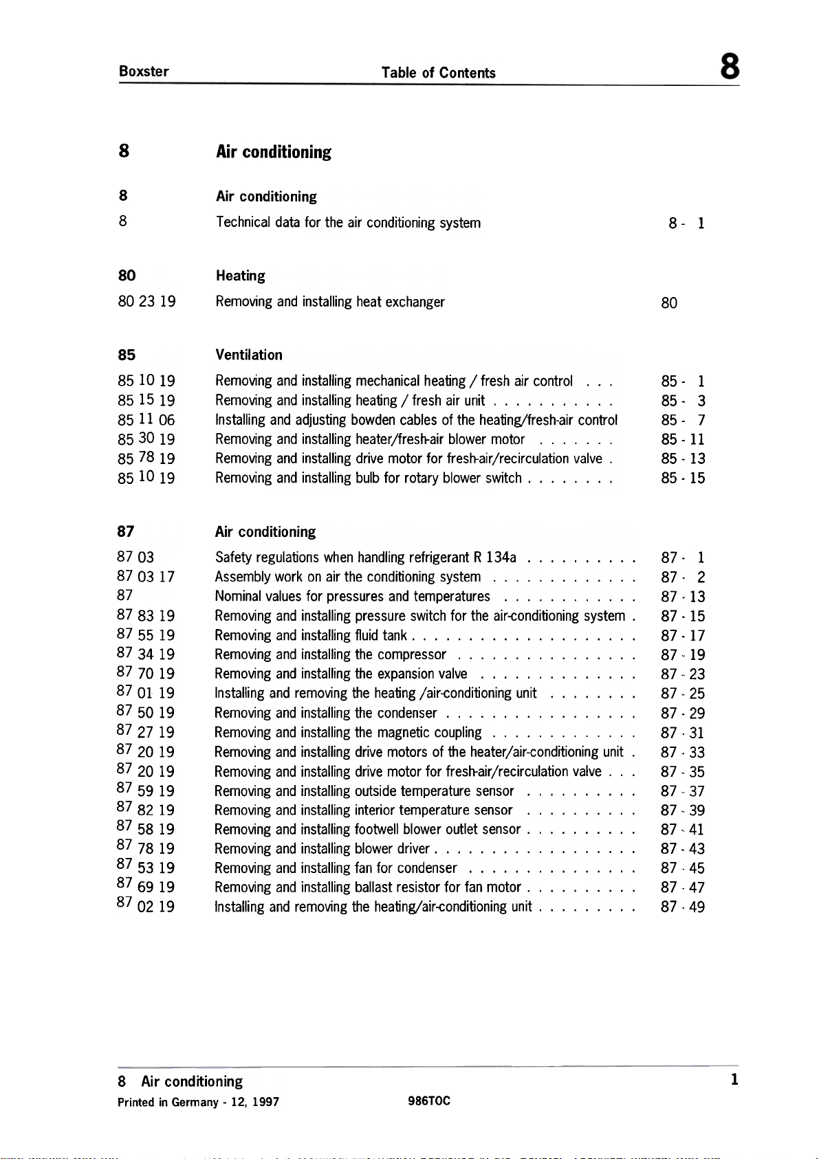
Air conditioning
Air conditioning
Technical data for the air conditioning system
Heating
Removing and installing heat exchanger
Ventilation
Removing and installing mechanical heating / fresh air control. ..
Removing and installing heating / fresh air unit. Installing and adjusting bowden cables of the heating/fresh-air control
Removing and installing heater/fresh-air blower motor. Removing and installing drive motor for fresh-air/recirculation valve.
Removing and installing bulb for rotary blower switch.
Air conditioning
8 -1
80
85- 1
85- 3
85- 7
85-11
85-13
85-15
87
87
87
87
87
87
87
87
87
87
87
87
87
87
87
87
87
87
87
03
0317
8319
5519
3419
7019
0119
5019
2719
2019
2019
5919
8219
5819
7819
5319
6919
0219
Safety regulations when handling refrigerant R 134a Assembly work on air the conditioning system. Nominal values for pressures and temperatures. Removing and installing pressure switch for the air-conditioning system.
Removing and installing fluid tank. Removing and installing the compressor. Removing and installing the expansion valve. Installing and removing the heating /air-conditioning unit. Removing and installing the condenser. Removing and installing the magnetic coupling. Removing and installing drive motors of the heater/air-conditioning unit.
Removing and installing drive motor for fresh-air/recirculation valve. ..
Removing ~nd installing outside temperature sensor. Removing and installing interior temperature sensor. Removing and installing footwell blower outlet sensor. Removing and installing blower driver. Removing and installing fan for condenser. Removing and installing ballast resistor for fan motor. Installing and removing the heatingjair-conditioning unit.
87.
87.
87.
87
87.
87.
87.
87.
87.
87.
87.
87.
87-
87-
87.
87.
87.
87.
87.
-2
-13-15
.17
.19
.23
-25.29
-31.33
-35
37
.39
.41
.43
.45
-47
-49
8 Air conditioning
Printed in Germany -12, 1997
-1
986TOC
1
Page 7
Boxster
Air conditioning
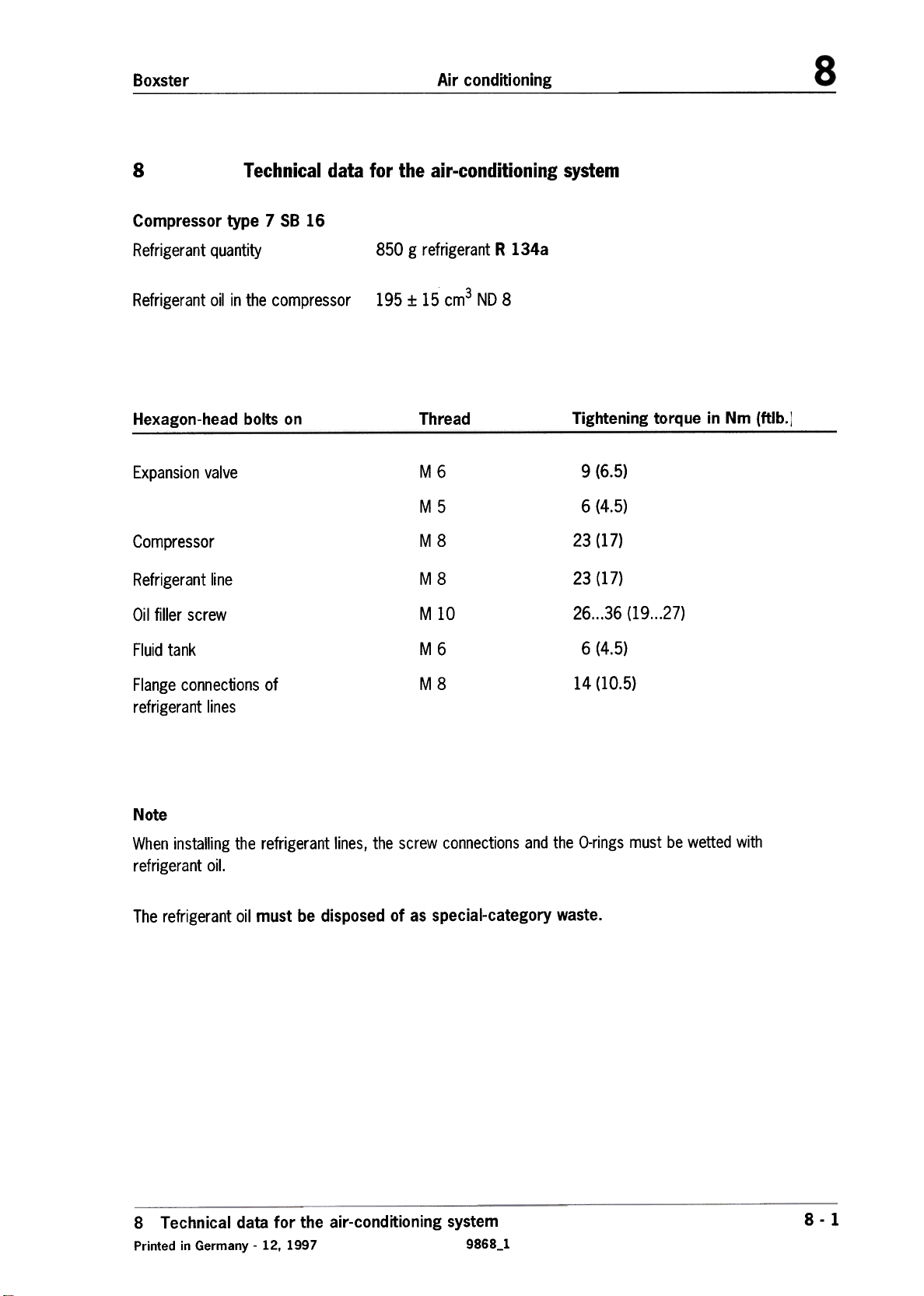
8
Compressor type 7 S8 16
Refrigerant quantity
Refrigerant oil in the compressor
Hexagon-head bolts on
Expansion valve
Technical data for the air-conditioning system
Compressor
Refrigerant line
Oil filler screw
850 g refrigerant R 134a
195 :f: 15 cm3 NO 8
Thread
M6
M5
M8 23 (17)
M8
M 10
Tightening torque in Nm (ftlb.]
9 (6.5)
6 (4.5)
23 (17)
26...36 (19...27)
Fluid tank
Flange connections of
refrigerant lines
Note
When installing the refrigerant lines, the screw connections and the a-rings must be wetted with
refrigerant oil.
The refrigerant oil must be disposed of as special-category waste.
M6
M8
6 (4.5)
14 (10.5)
8 Technical data for the air-conditioning system
Printed in Germany -12, 1997 9868_1
8 -1
Page 8
Boxster
Heating
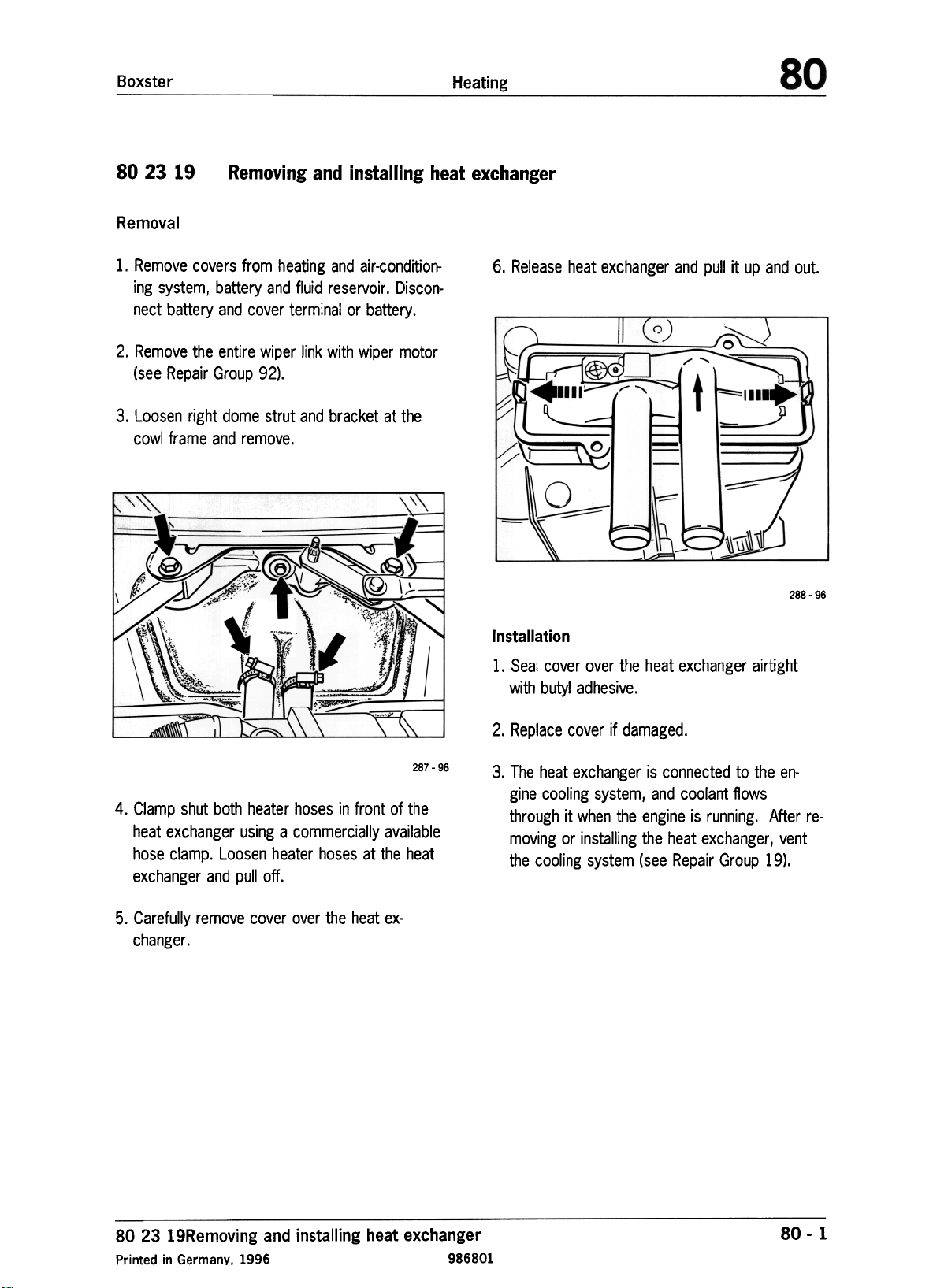
80 23 19
Removal
1. Remove covers from heating and air-conditioning system, battery and fluid reservoir. Disconnect battery and cover terminal or battery.
2. Remove the entire wiper link with wiper motor
(see Repair Group 92).
3. Loosen right dome strut and bracket at the
cowl frame and remove.
\ " '" '"
'/
Removing and installing heat exchanger
\\\
~,~
.~
\ \ -
,.--
~
""
\
6. Release heat exchanger and pull it up and out.
c
~ ~---='
~)
'""-'
,: "'"
t
)
::::::;;;;~!)
u
--=
a:\~
288 -96
Installation
1. Seal cover over the heat exchanger airtight
with butyl adhesive.
I~
4. Clamp shut both heater hoses in front of the
heat exchanger using a commercially available
hose clamp. Loosen heater hoses at the heat
exchanger and pull off.
5. Carefully remove cover over the heat exchanger.
\.
287 -96
2. Replace cover if damaged.
3. The heat exchanger is connected to the engine cooling system, and coolant flows
through it when the engine is running. After removing or installing the heat exchanger I vent
the cooling system (see Repair Group 19).
80 23 19Removing and installing heat exchanger
Printed in Germany. 1996 986801
80 -1
Page 9
Boxster
Ventilation
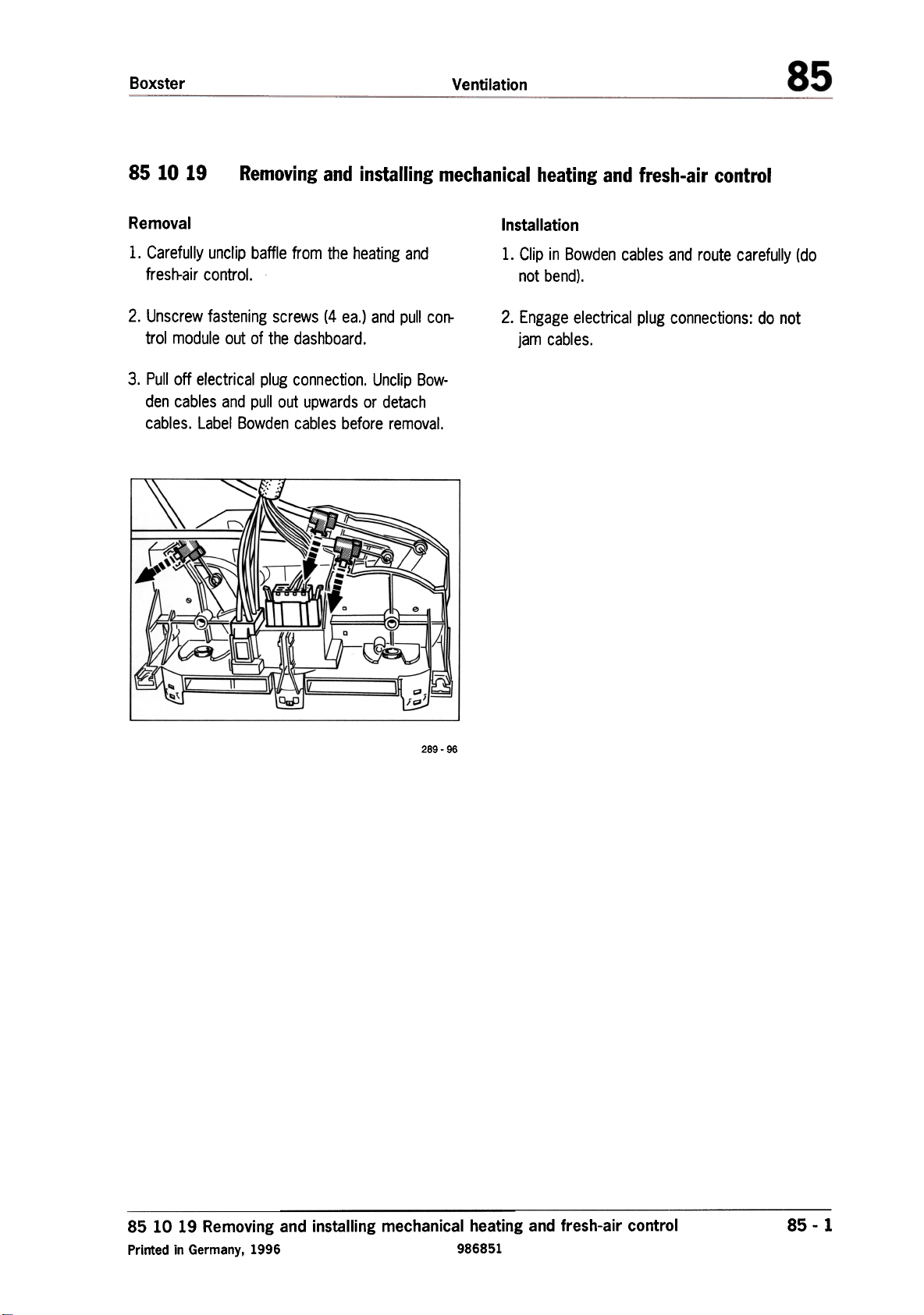
85 10 19
Removal
1. Carefully unclip baffle from the heating and
fresh-air control.
2. Unscrew fastening screws (4 ea.) and pull corr
trol module out of the dashboard.
3. Pull off electrical plug connection. Unclip Bowden cables and pull out upwards or detach
cables. Label Bowden cables before removal.
Removing and installing mechanical heating and fresh-air control
.,..
Installation
1. Clip in Bowden cables and route carefully (do
not bend),
2. Engage electrical plug connections: do not
jam cables.
..U.;
M
~=\ ~-
j~'
289 -96
~
I!!-
85 10 19 Removing and installing mechanical heating and fresh-air control
Printed in Germany, 1996 986851
85 -1
Page 10
Boxster
Ventilation
85 15 19 Removing and installing heating and fresh-air control
Removal
1. Remove covers over heating and fresh-air control, battery and fluid reservoir. Disconnect bat-
tery and remove.
2. Remove steering wheel and loosen steeringcolumn panel. Comply with safety regulations
when handling airbag units (see Repair Group
169).
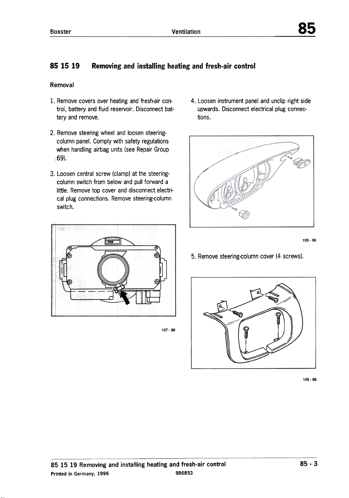
3. Loosen central screw (clamp) at the steeringcolumn switch from below and pull forward a
little. Remove top cover and disconnect electri-
cal plug connections. Remove steering-column
switch.
4. Loosen instrument panel and unclip right side
upwards. Disconnect electrical plug connections.
108- 96
5. Remove steering-column cover (4 screws).
107-96
85 15 19 Removing and installing heating and fresh-air control
Printed in Germany, 1996 986853
109 -96
85 -3
Page 11
Ventilation Boxster
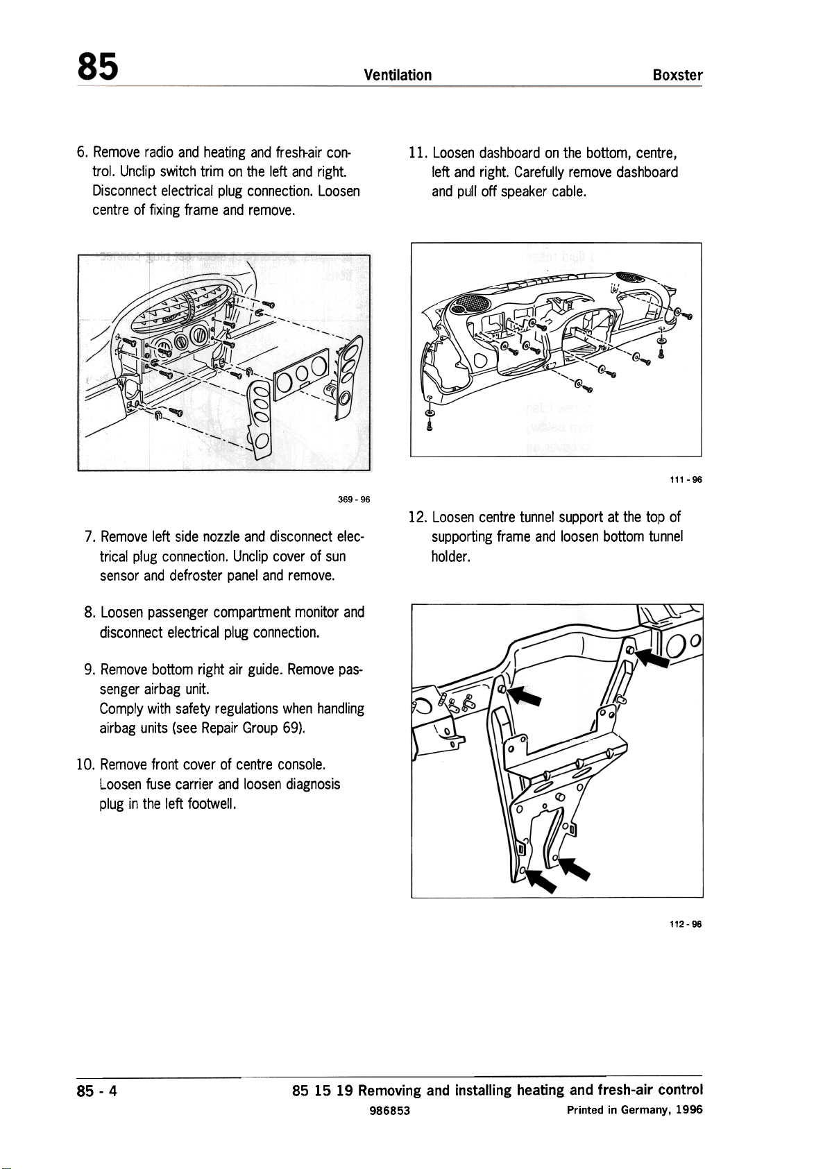
6. Remove radio and heating and fresh-air control. Unclip switch trim on the left and right.
Disconnect electrical plug connection. Loosen
centre of fixing frame and remove.
369-96
7. Remove left side nozzle and disconnect electrical plug connection. Unclip cover of sun
sensor and defroster panel and remove.
11. Loosen dashboard on the bottom, centre,
left and right. Carefully remove dashboard
and pull off speaker cable.
111 -96
12. Loosen centre tunnel support at the top of
supporting frame and loosen bottom tunnel
holder.
8. Loosen passenger compartment monitor and
disconnect electrical plug connection.
9. Remove bottom right air guide. Remove pas-
senger airbag unit.
Comply with safety regulations when handling
airbag units (see Repair Group 69).
10. Remove front cover of centre console.
Loosen fuse carrier and loosen diagnosis
plug in the left footwell.
"'""
l \ \)
--
A1co""'""'-"-"' c
-..co
112 -96
~
85 -4
85 15 19 Removing and installing heating and fresh-air control
986853 Printed in Germany, 1996
Page 12
Boxster
Ventilation
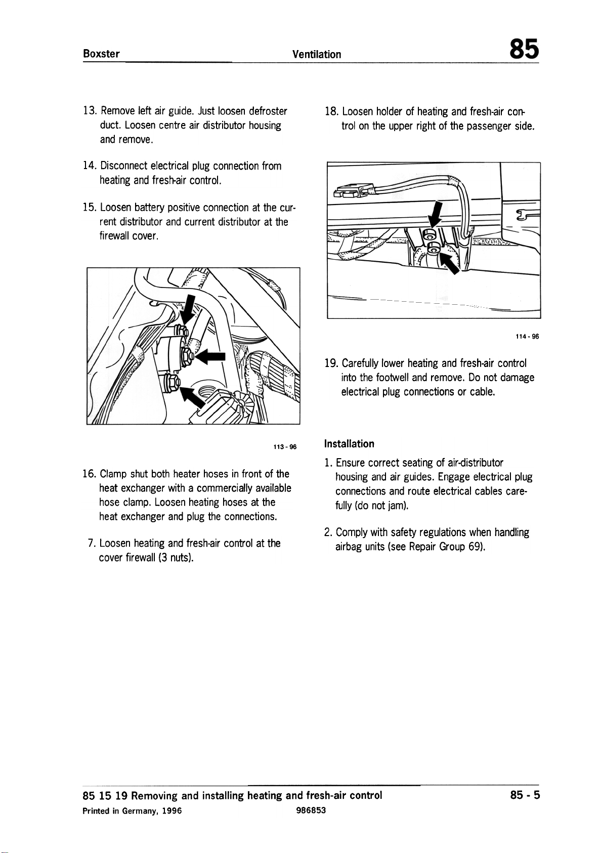
13. Remove left air guide. Just loosen defroster
duct. Loosen centre air distributor housing
and remove.
14. Disconnect electrical plug connection from
heating and fresh-air control.
15. Loosen battery positive connection at the current distributor and current distributor at the
firewall cover.
~
/
~
(
/
\"f;'
18. Loosen holder of heating and fresh-air control on the upper right of the passenger side.
~
--
---
:~"'~;~;;;/
114- 96
19. Carefully lower heating and fresh-air control
into the footwell and remove. Do not damage
electrical plug connections or cable.
/C/
113-96
16. Clamp shut both heater hoses in front of the
heat exchanger with a commercially available
hose clamp. Loosen heating hoses at the
heat exchanger and plug the connections.
7, Loosen heating and fresh-air control at the
cover firewall (3 nuts),
Installation
1. Ensure correct seating of air-distributor
housing and air guides. Engage electrical plug
connections and route electrical cables carefully (do not jam).
2. Comply with safety regulations when handling
airbag units (see Repair Group 69).
85 15 19 Removing and installing heating and fresh-air control
Printed in Germany, 1996 986853
85 -5
Page 13
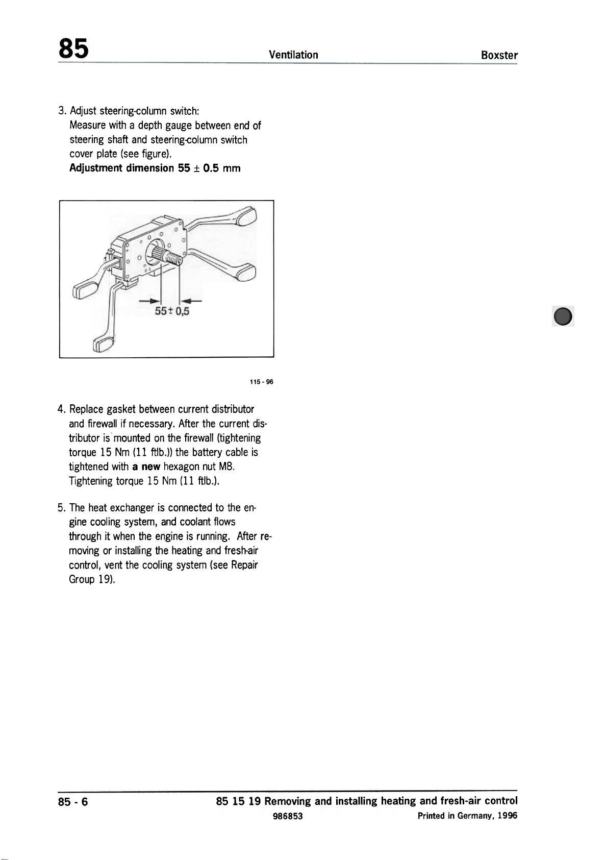
3. Adjust steering-column switch:
Measure with a depth gauge between end of
steering shaft and steering-column switch
cover plate (see figure).
Adjustment dimension 55 :t 0.5 mm
Ventilation
Boxster
4. Replace gasket between current distributor
and firewall if necessary. After the current dis-
tributor is mounted on the firewall (tightening
torque 15 Nm (11 ftlb.)) the battery cable is
tightened with a new hexagon nut M8.
Tightening torque 15 Nm (11 ftlb.).
5. The heat exchanger is connected to the engine cooling system, and coolant flows
through it when the engine is running. After removing or installing the heating and fresh-air
control, vent the cooling system (see Repair
Group 19).
115 -96
85-6
85 15 19 Removing and installing heating and fresh-air control
986853 Printed in Germany, 1996
Page 14
Boxster
Ventilation
85 11 06
Note
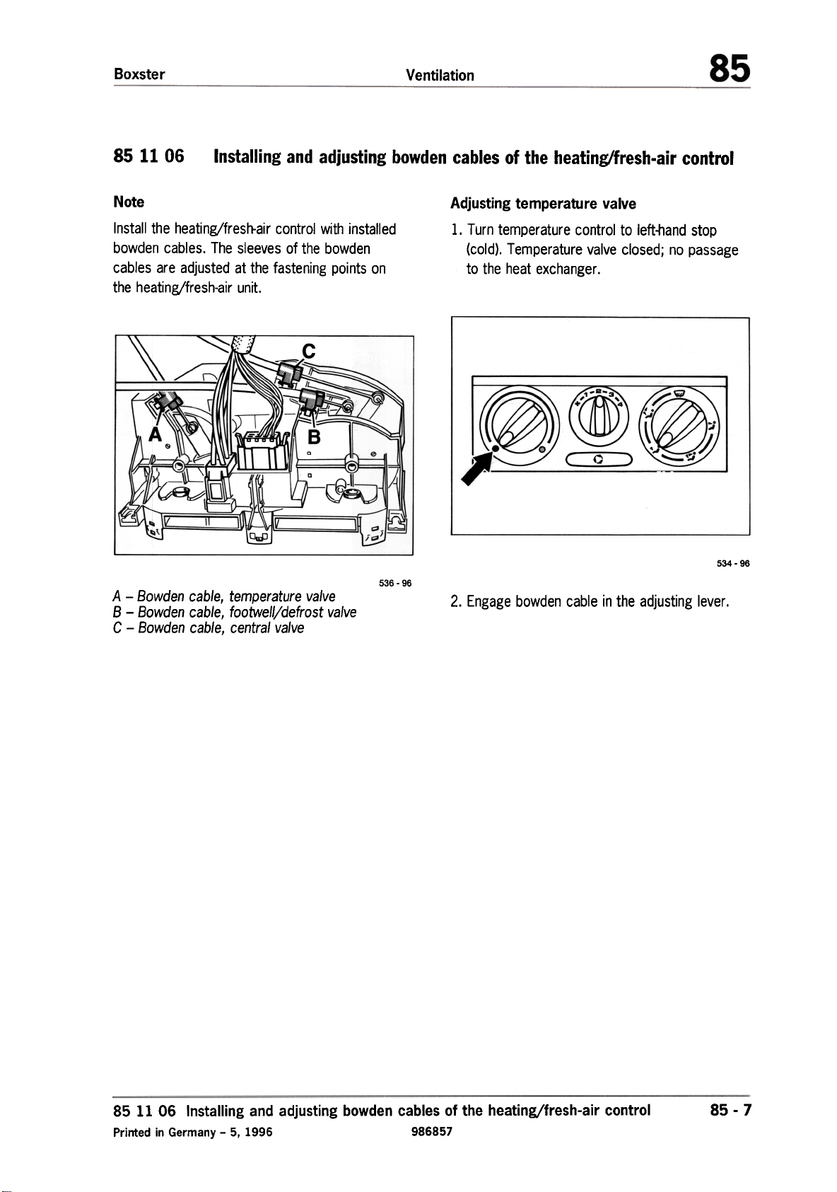
Install the heating/fresh-air control with installed
bowden cables. The sleeves of the bowden
cables are adjusted at the fastening points on
the heating/fresh-air unit.
Installing and adjusting bowden cables of the heating/fresh-air control
c
A
...
/"
B
0
\\
h
~I
00
A -Bowden cable, temperature valve
B -Bowden cable, footwelVdefrost valve
C -Bowden cable, central valve
"';~
536 -96
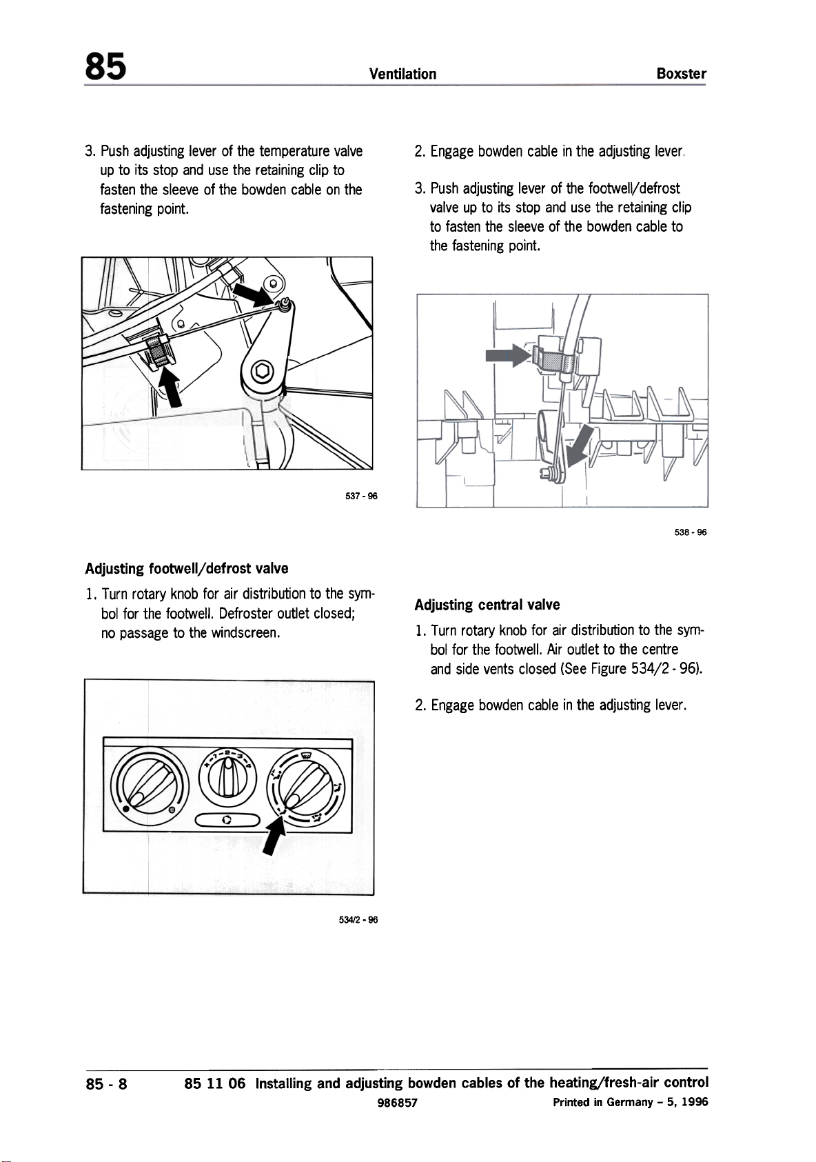
Adjusting temperature valve
1. Turn temperature control to left-hand stop
(cold). Temperature valve closed; no passage
to the heat exchanger.
534 -96
2. Engage bowden cable in the adjusting lever.
~
,"-~
85 11 06 Installing and adjusting bowden cables of the heating/fresh-air control
Printed in Germany -5, 1996 986857
85 -7
Page 15
Ventilation
Boxster
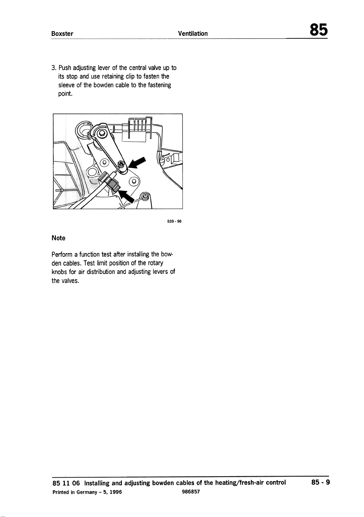
3. Push adjusting lever of the temperature valve
up to its stop and use the retaining clip to
fasten the sleeve of the bowden cable on the
fastening point.
\)
~(o))
IU-
y
://:
')
/"
-/
537 -96
2. Engage bowden cable in the adjusting lever.
3. Push adjusting lever of the footwelljdefrost
valve up to its stop and use the retaining clip
to fasten the sleeve of the bowden cable to
the fastening point.
538 -96
Adjusting footwelljdefrost valve
1. Turn rotary knob for air distribution to the symbol for the footwell. Defroster outlet closed;
no passage to the windscreen.
53412 -96
Adjusting central valve
1. Turn rotary knob for air distribution to the symbol for the footwell. Air outlet to the centre
and side vents closed (See Figure 534/2 -96).
2. Engage bowden cable in the adjusting lever.
~
85-8
85 11 06 Installing and adjusting bowden cables of the heating/fresh-air control
986857 Printed in Germany -5, 1996
Page 16
3. Push adjusting lever of the central valve up to
its stop and use retaining clip to fasten the
sleeve of the bowden cable to the fastening
point.
~
VentilationBoxster
539 -96
Note
Perform a function test after installing the bowden cables. Test limit position of the rotary
knobs for air distribution and adjusting levers of
the valves.
85 11 06 Installing and adjusting bowden cables of the heating/fresh-air control
Printed in Germany -5, 1996 986857
85 -9
Page 17
VentilationBoxster
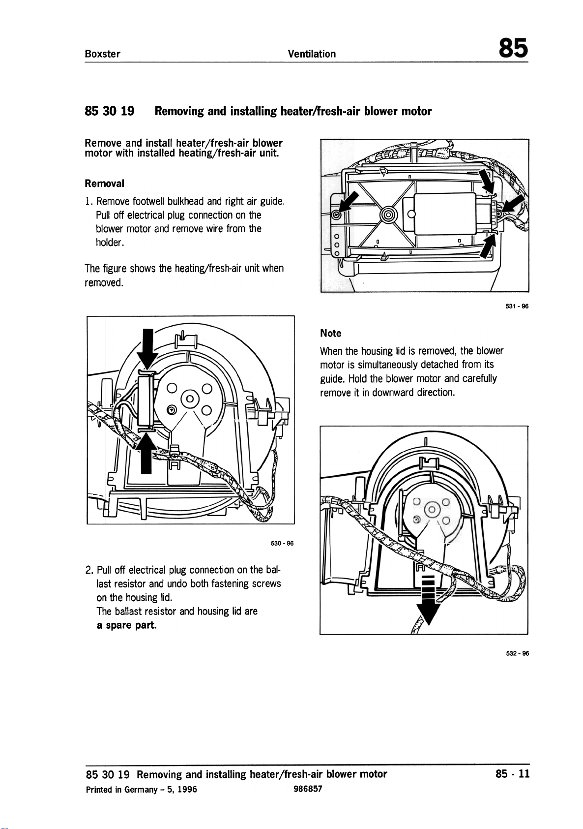
85 30 19 Removing and installing heater/fresh-air blower motor
Remove and install heater/fresh-air blower
motor with installed heating/fresh-air unit.
Removal
1. Remove footwell bulkhead and right air guide.
Pull off electrical plug connection on the
blower motor and remove wire from the
holder.
The figure shows the heating/fresh-air unit when
removed.
Note
531 -96
""""
J'
cb
j
530-96
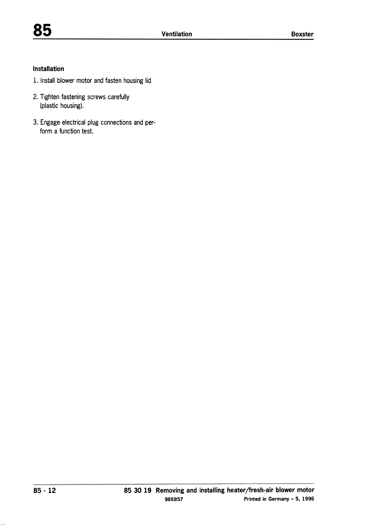
2. Pull off electrical plug connection on the bal-
last resistor and undo both fastening screws
on the housing lid.
The ballast resistor and housing lid are
a spare part.
When the housing lid is removed, the blower
motor is simultaneously detached from its
guide. Hold the blower motor and carefully
remove it in downward direction.
~
-
-
I~
a
{/
,hr~
;-
85 30 19 Removing and installing heater/fresh-air blower motor
Printed in Germany -5, 1996 986857
532-96
85 -11
Page 18
In!;tallation
1. Install blower motor and fasten housing lid,
2. Tighten fastening screws carefully
(plastic housing).
3. Engage electrical plug connections and perform a function test.
Ventilation
Boxster
8~) -12
85 30 19 Removing and installing heater/fresh-air blower motor
986857 Printed in Germany -5, 1996
Page 19
Boxster
Ventilation
85 78 19 Removing and installing drive motor for fresh-air/recirculation valve
I~emove and install drive motor on installed
heating/fresh-air unit
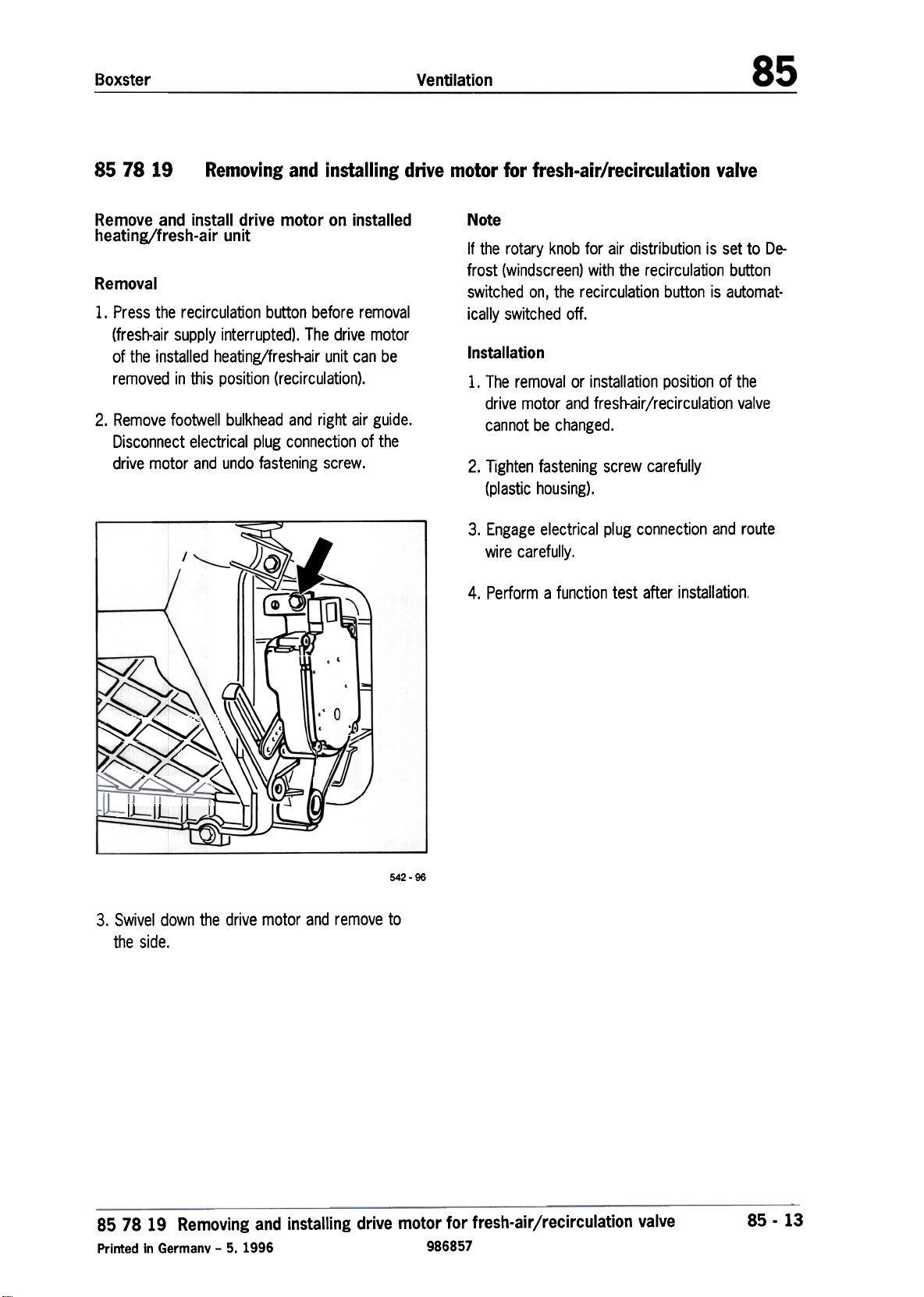
Removal
1. Press the recirculation button before removal
(fresh-air supply interrupted), The drive motor
of the installed heating/fresh-air unit can be
removed in this position (recirculation).
2. Remove footwell bulkhead and right air guide.
Disconnect electrical plug connection of the
drive motor and undo fastening screw.
/ '-
I
~~~'-
Note
If the rotary knob for air distribution is set to Defrost (windscreen) with the recirculation button
switched on, the recirculation button is automat-
ically switched off.
Installation
1. The removal or installation position of the
drive motor and fresh-air/recirculation valve
cannot be changed.
2. Tighten fastening screw carefully
(plastic housing),
3. Engage electrical plug connection and route
wire carefully.
4. Perform a function test after installation.
~
-<
~
542 -96
3. Swivel down the drive motor and remove to
the side.
85 78 19 Removing and installing drive motor for fresh-air/recirculation valve
Printed in Germany -5. 1996 986857
85 -13
Page 20
Boxster
Ventilation
85 10 19
Removal
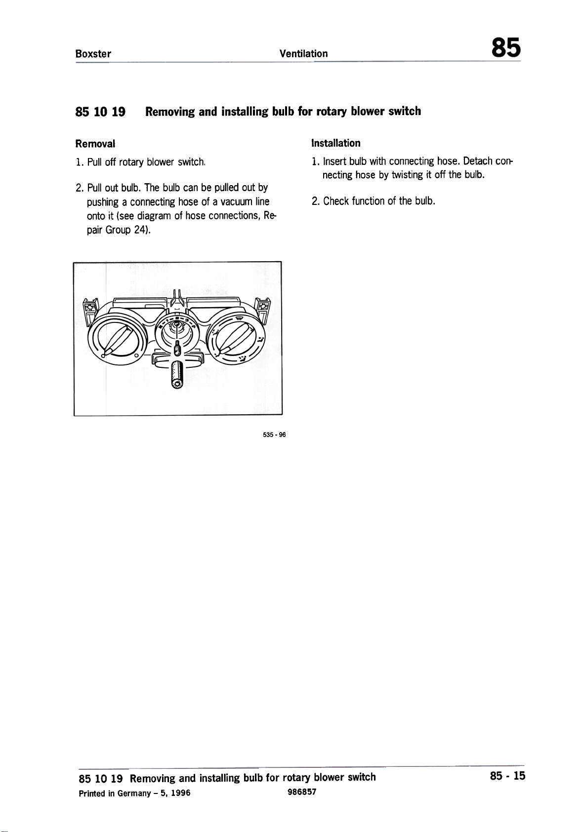
Removing and installing bulb for rotary blower switch
1. Pull off rotary blower switch.
2. Pull out bulb. The bulb can be pulled out by
pushing a connecting hose of a vacuum line
onto it (see diagram of hose connections, Re-
pair Group 24).
Installation
1. Insert bulb with connecting hose. Detach connecting hose by twisting it off the bulb.
2. Check function of the bulb.
535 -96
85 10 19 Removing and installing bulb for rotary blower switch
Printed in Germany -5, 1996 986857
85 -15
Page 21
Boxster
Air conditioning
8703
The refrigerant R 134a which is used is known
as a safety refrigerant. This means that this refrigerant is non-flammable, non-explosive, nontoxic, non-irritating, odorless and tasteless. Des-
pite this, you should still follow the points below.
1. Avoid all contact with liquid or gaseous refrigerants. Treat affected skin in the same way as
in the case of freezing. Rinse immediately with
cold water and then consult a physician. Wear
safety goggles to protect your eyes. If refrige-
rant still gets in your eyes, consult a physician
immediately. Wear rubber gloves to protect
your hands.
2. When carrying out repairs on the air-conditioning system, the system must be emptied by
suction and the refrigerant must be purified.
Chlorine-free refrigerants must also not be
allowed to escape into the atmosphere and
must be disposed of correctly.
Due to their chemical composition, different refrigerants must not be mixed with each other
(not even in small quantities),
Safety regulations when handling refrigerant R 134a
4. Refrigerant bottles must not be thrown and
must not be subjected to direct sunlight or
other heat sources for an extended period
when full. The maximum permissible temperature of a filled refrigerant bottle must not ex-
ceed 45 °C.
3. Never perform welding work on parts of the
closed air-conditioning system or in its immediate vicinity. Whether or not the system is filled
with refrigerant, the heating causes a very
strong overpressure which can cause damage
to the system or even lead to an explosion.
R 134a is completely non-toxic at normal tem-
peratures, but it decomposes upon contact
with a flame or at high temperatures.
87 03 Safety regulations when handling refrigerant R 134a
Printed in Germany -1996 986871
87. 1
Page 22
Air conditioning
Boxster
87 03 17
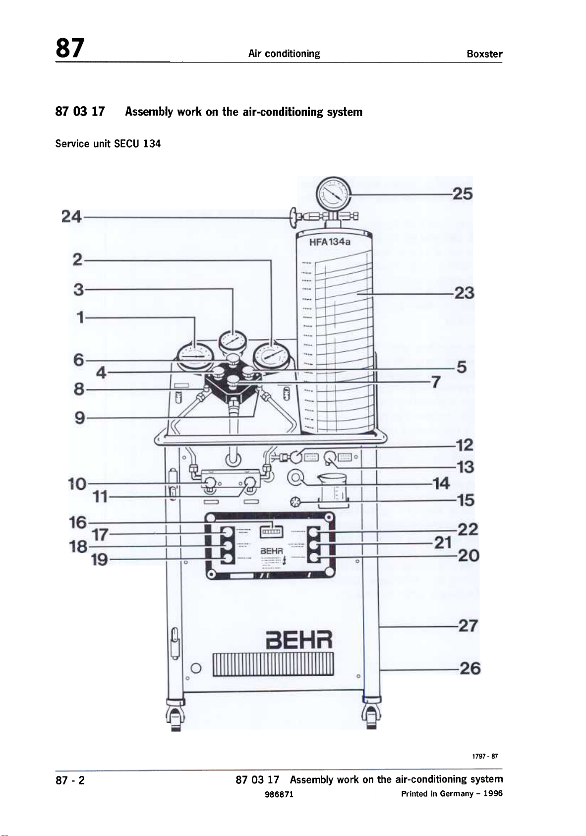
Service unit SECU 134
Assembly work on the air-conditioning system
87-2
1797 -87
87 03 17 Assembly work on the air-conditioning system
986871 Printed in Germany -1996
Page 23
Boxster
Air conditioning
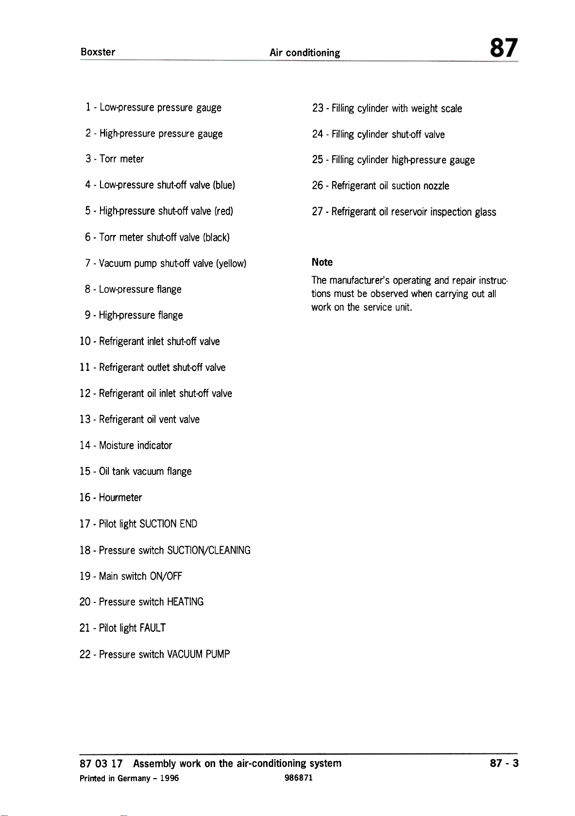
1 -Low-pressure pressure gauge
2 -High-pressure pressure gauge
3 -Torr meter
4 -Low-pressure shut-off valve (blue)
5 -High-pressure shut-off valve (red)
6 -Torr meter shut-off valve (black)
7 -Vacuum pump shut-off valve (yellow)
8 -Low-pressure flange
9 -High-pressure flange
10 -Refrigerant inlet shut-off valve
11 -Refrigerant outlet shut-off valve
23 -Filling cylinder with weight scale
24 -Filling cylinder shut-off valve
25 -Filling cylinder high-pressure gauge
26 -Refrigerant oil suction nozzle
27 -Refrigerant oil reservoir inspection glass
Note
The manufacturer's operating and repair instruc.
tions must be observed when carrying out all
work on the service unit.
12 -Refrigerant oil inlet shut-off valve
13 -Refrigerant oil vent valve
14 -Moisture indicator
15 -Oil tank vacuum flange
16 -Hourmeter
17 -Pilot light SUCTION END
18 -Pressure switch SUCTION/CLEANING
19 -Main switch ON/OFF
20 -Pressure switch HEATING
21 -Pilot light FAULT
22 -Pressure switch VACUUM PUMP
87 03 17 Assembly work on the air-conditioning system
Printed in Germany -1996 986871
87-3
Page 24
Air conditioning
Boxster
Assembly work involving the refrigerant
system
During all work on the air-conditioning system
which necessitates opening the refrigerant sys-
tem, the system contents must first be dis-
posed of correctly. When doing so, follow the
safety regulations.
Dirt and moisture must be kept out of the air-conditioning system's pipe system. Thorough cleanliness must therefore be ensured during all work.
System components must never be cleaned on
the inside with hot steam. Use only nitrogen for
cleaning purposes.
When replacing a component, all openings must
be closed off with suitable plugs.
General assembly sequence
1. Remove refrigerant by suction.
2. Remove faulty part.
3. Evacuate.
4. Check the system for leaks.
5. Rinse with refrigerant.
6. Empty the system by suction again.
7. Evacuate.
Fill.
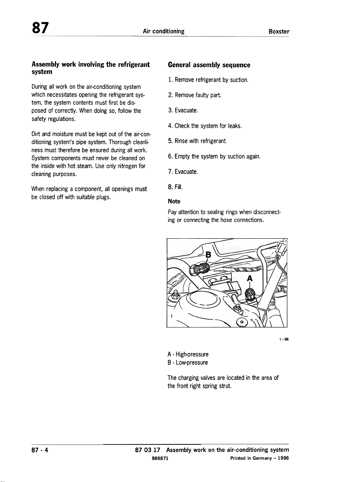
Note
Pay attention to sealing rings when disconnect-
ing or connecting the hose connections.
~
A
I;
,
:
/
\.
A -High-pressure
B -Low-pressure
The charging valves are located in the area of
the front right spring strut.
1 -96
87-4
8.
~::.~:::::::::=::::=:::.;.,,-'
~~~
87 03 17 Assembly work on the air-conditioning system
986871 Printed in Germany -1996
Page 25
Boxster
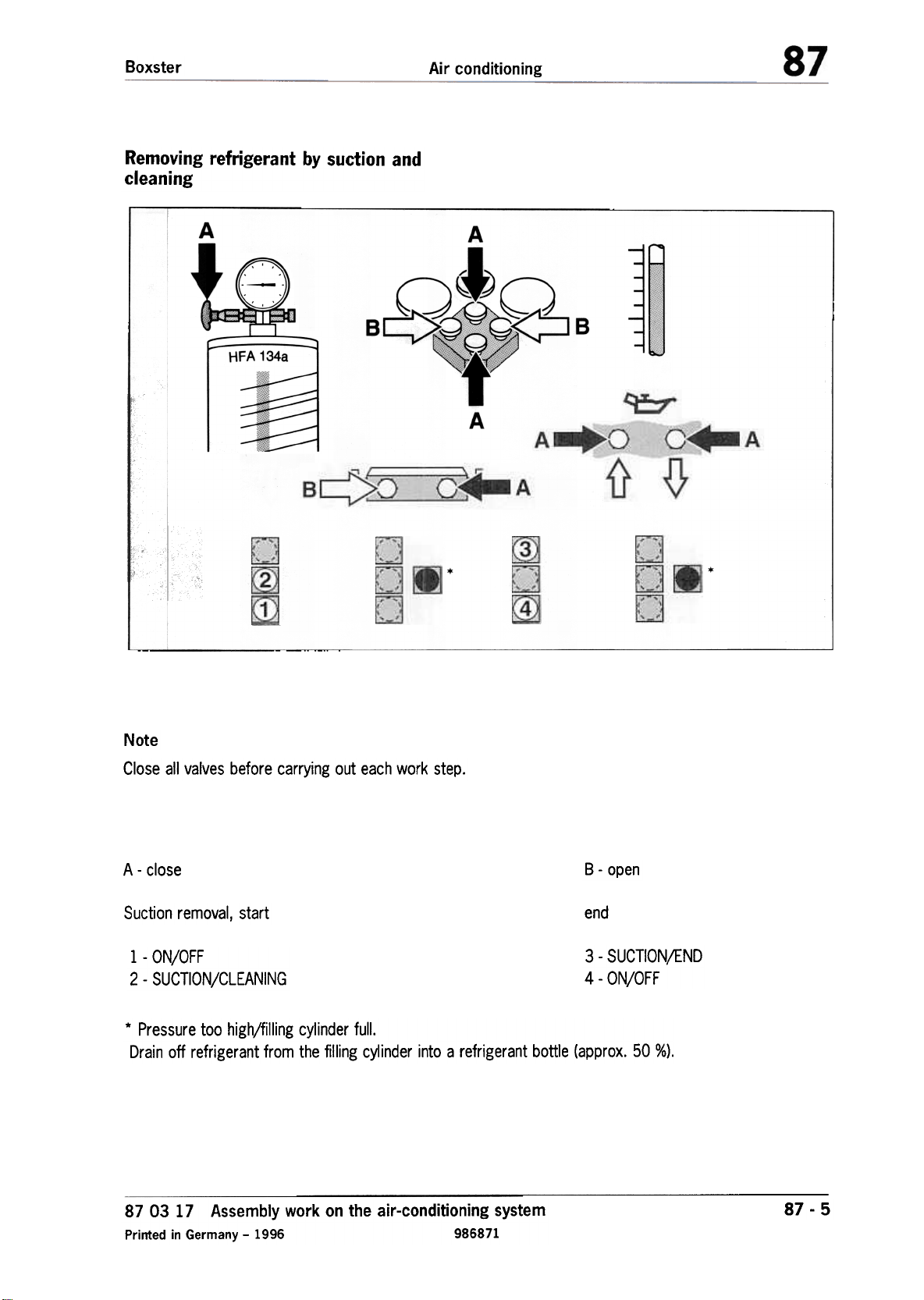
Removing refrigerant by suction and
cleaning
Air conditioning
A
A
B
A
Note
Close all valves before carrying out each work step.
A-close
Suction removal, start
1 -ON/OFF
2 -SUCTION/CLEANING
* Pressure too high/filling cylinder full.
Drain off refrigerant from the filling cylinder into a refrigerant bottle (approx. 50 %).
B -open
end
3 -SUCTIONjEND
4 -ON/OFF
87 03 17 Assembly work on the air-conditioning system
Printed in Germany -1996 986871
87-5
Page 26
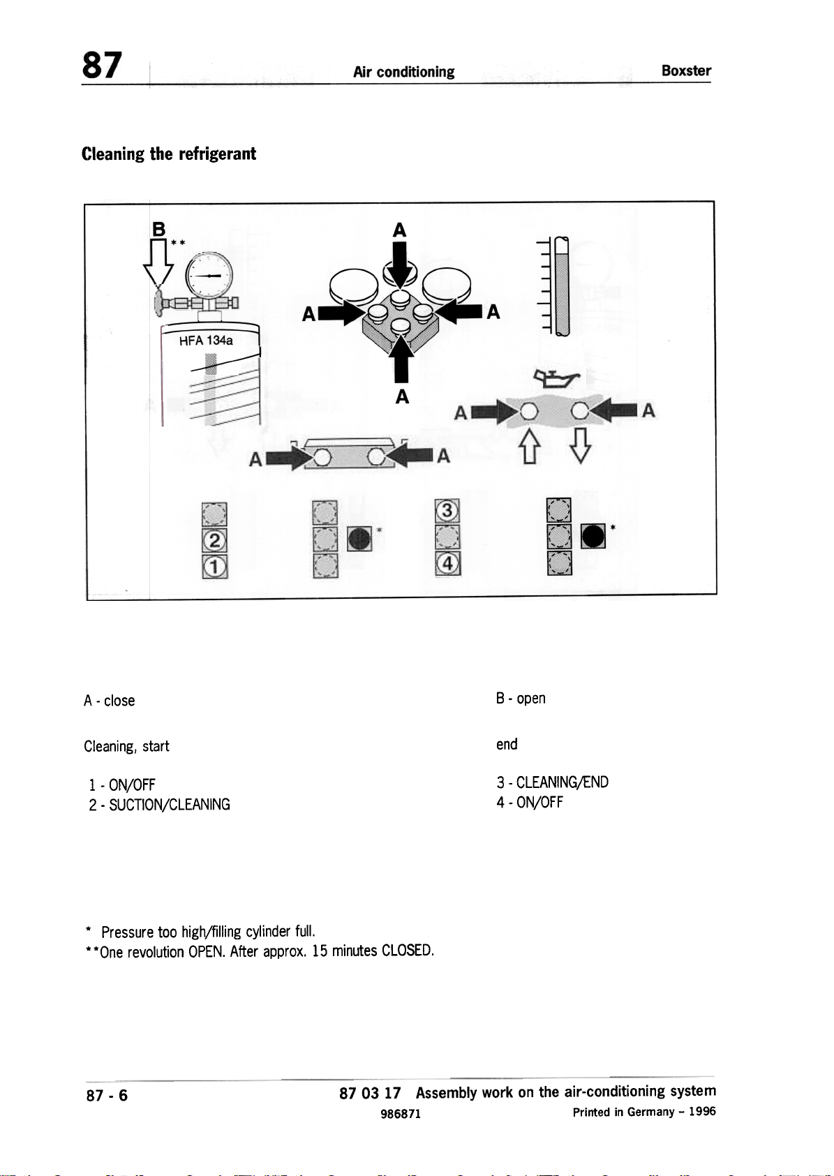
(:Ieaning the refrigerant
BJJ'(-..
.:::::~~~~~=~
A
A
A
A-close
Cleaning, start
1 -ON/OFF
2 -SUCTION/CLEANING
* Pressure too high/filling cylinder full.
**One revolution OPEN. After approx. 15 minutes CLOSED.
87 -6
87 03 17 Assembly work on the air-conditioning system
986871 Printed in Germany -1996
B -open
end
3 -CLEANING/END
4 -ON/OFF
Page 27
Boxster
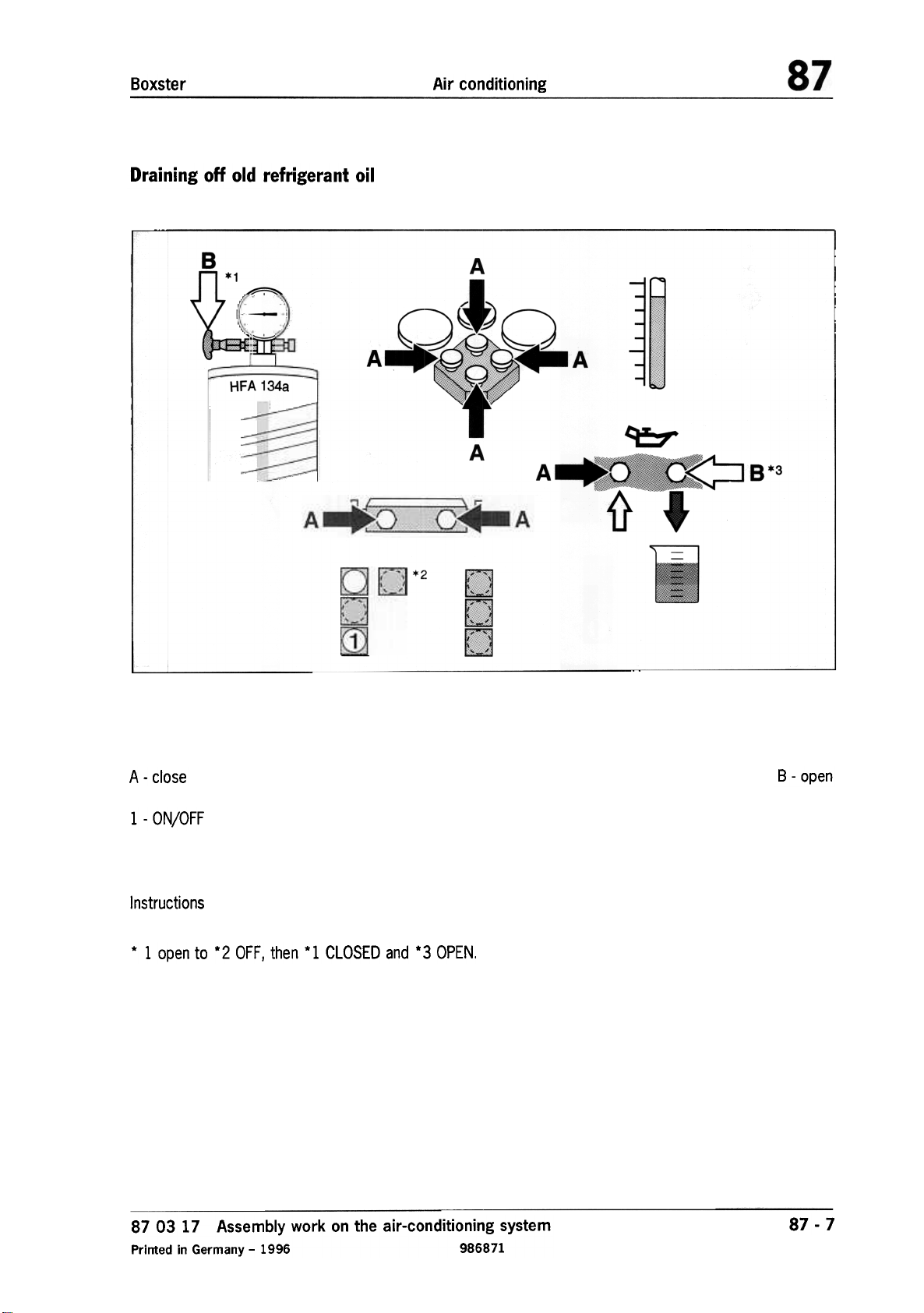
Draining off old refrigerant oil
Air conditioning
B
A
~
-
~
m
HFA 134a
~.
A
A 8*3
"1} """'f
*2
A -close
1 -ON/OFF
Instructions
* 1 open to *2 OFF, then *1 CLOSED and *3 OPEN.
87 03 17 Assembly work on the air-conditioning system
Printed in Germany -1996 986871
B -open
87-7
Page 28
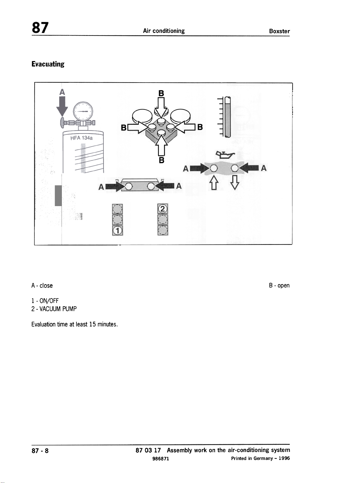
E'vacuating
Air conditioning
B
Boxster
B
A -close B -open
1 -ON/OFF
2 -VACUUM PUMP
Evaluation time at least 15 minutes.
87 -8
87 03 17 Assembly work on the air-conditioning system
986871 Printed in Germany -1996
Page 29
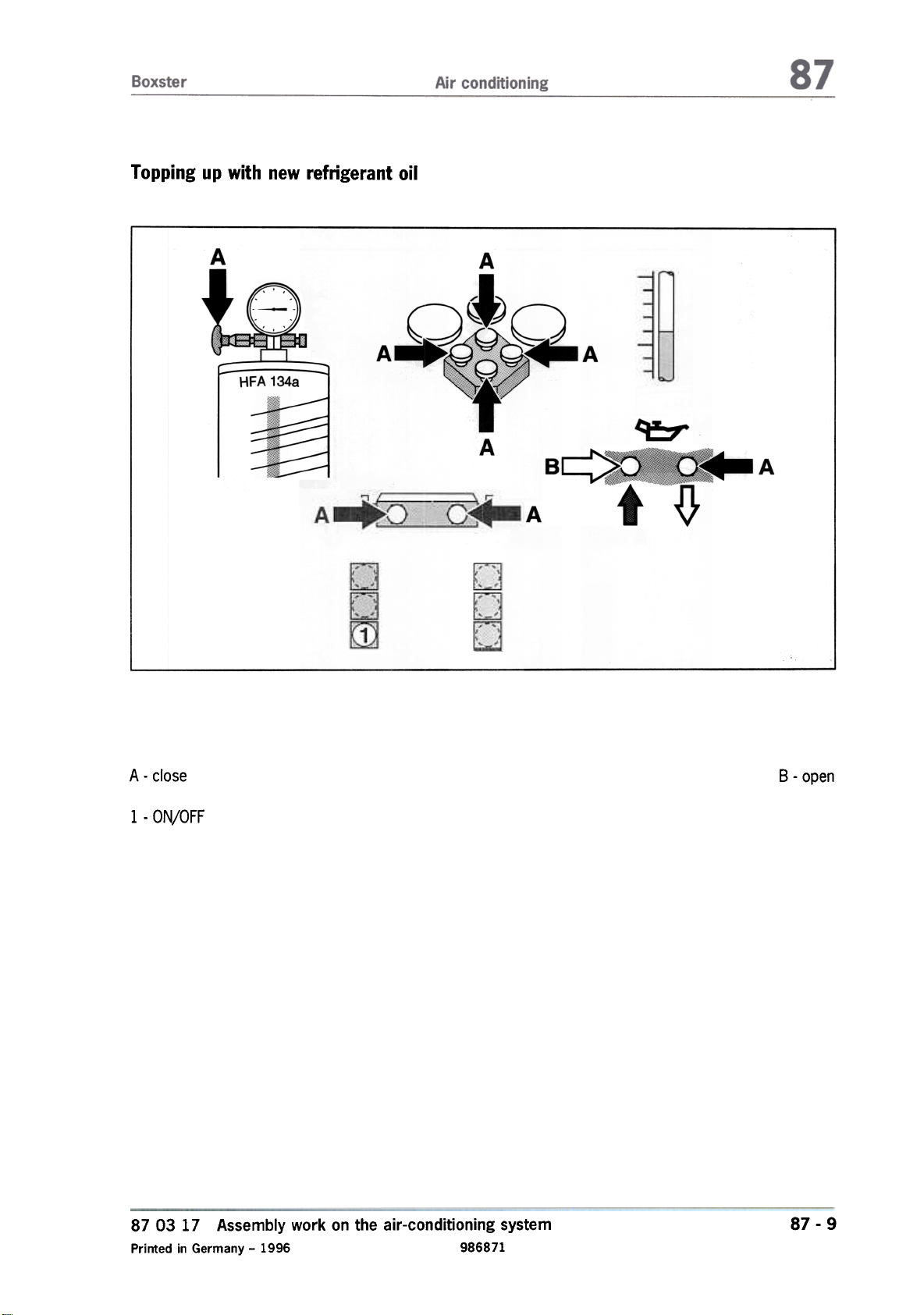
Topping up with new refrigerant oil
A
A
A -close
1 -ON/OFF
87 03 17 Assembly work on the air-conditioning system
Printed in Germany -1996 986871
B -open
87 -9
Page 30
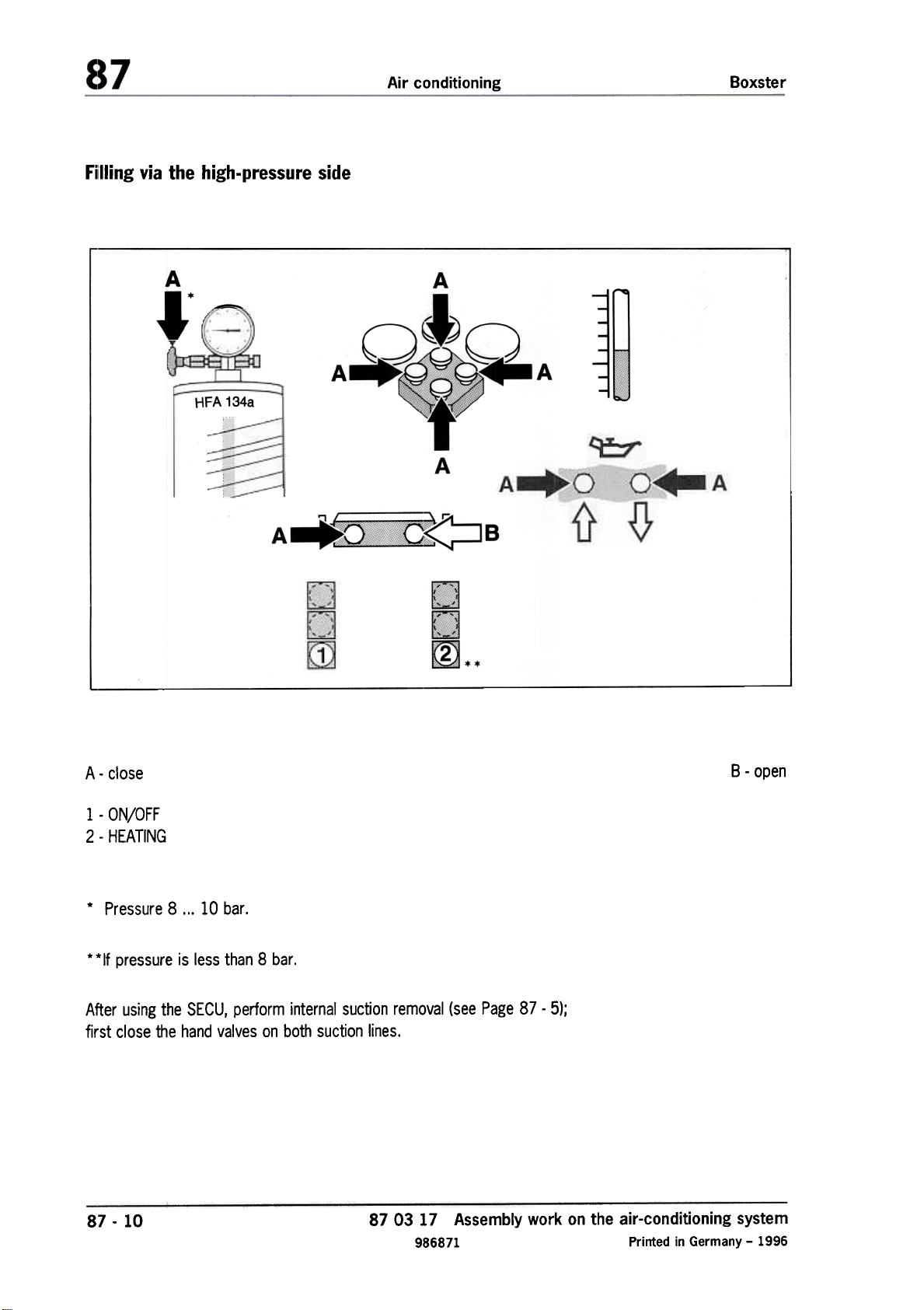
Filling via the high-pressure side
Air conditioning
Boxster
AI'
A
.-.
-
HFA 134a
A
A -close
1 -ON/OFF
2 -HEATING
* Pressure 8 ...10 bar.
* * If pressure is less than 8 bar.
After using the SECU, perform internal suction removal (see Page 87 -5);
first close the hand valves on both suction lines.
87 -10
87 03 17 Assembly work on the air-conditioning system
986871 Printed in Germany -1996
B -open
m
Page 31

Boxster Air conditioning
Refilling the air-conditioning system
Note
In the event of insufficient refrigeration
performance, remove the refrigerant by suction,
top up with the stipulated quantity and check the
system for leaks.
1. Remove the refrigerant by suction using the
service unit.
2. Determine the refrigerant oil quantity after the
refrigerant has been removed by suction.
3. Fill up with new refrigerant oil.
4. Evacuate.
5. Fill with the stipulated amount of refrigerant.
6. Check the system for leaks,
87 03 17 Assembly work on the air-conditioning system
Printed in Germany -16, 1997 986871
87 -11
Page 32

Distribution of the oil quantity in the refrigerant circuit
Total oil quantity
195:t 15 cm3
After suction removal from the system, the
following quantities remain in the
condenser 2 x 20 cm3
evaporator
approx. 40 cm3
approx. 30 cm3
fluid tank
with lines
compressor
approx. 30 cm3
approx. 50 cm3
circulating oil quantity
in the refrigerant circuit
approx. 60 cm3
Note
In new vehicles, the amount of oil removed by
suction is approx. 15 ...40 cm3.
Oil removed by suction must be returned to the
system.
Refrigerant oil removed from a previously run
air-conditioning system may no longer be used
(special-category waste).
After the refrigerant has been removed by
suction and a component has been replaced,
the oil quantity must be determined and topped
up by the quantity remaining in the removed
component.
87 -12
87 03 17 Assembly work on the air-conditioning system
986871 Printed in Gennany -16, 1997
Page 33

87
Nominal values for pressures and temperatures
Note
The temperature of the air from the "centre" dashboard vents must lie within the prescribed tolerance
range within 5 minutes, depending on the ambient temperature (see diagram).
General test prerequisites
Close doors, windows and sliding roof
Insert temperature probe into centre vent
Measure ambienttemprature
Open all dashboard vents
Switch ignition on
Press recirculating-air button
Set temperature control to maximum cooling
Switch fresh-air blower to stage 4
Start engine
Operate air condition while idling
Set engine speed to 2000 rpm (start of time measurement)
If the prescribed nominal values are not reached, the cooling system must be checked for leaks and re-
paired.
10
u
0
8
oS
Q)
'-
~
"'ro
'-
6
Q)
Co
E
Q)
4
c:
~
Q)
~
2
Q)
u
Centre vent temperature as a function of ambient temperature
15
20
25
Ambient temperature in °C
30 35 40
87 Nominal values for pressures and temperatures
Printed in Germany, 1996 9868713
87 -13
~
Page 34

Air conditioning
f\lominal values for pressures and temperatures
30
25
Boxster
20
15
10
L~ """""""
5
15
High pressure in cold circuit as a function of ambient temperature
1,8
1,7
20
Ambient temperature in °C
25 30
~
35 40
1,6
,-
(0
~:)
1,5
.!:
(I)
,-
::J
(II
(II
1,4
(I)
1-
1:1-
:~
1,3
(:)
_.J
Low pressure in cold circuit as a function of ambient temperature
8:7 -14
15 20 25
Ambient temperature in DC
30
87 Nominal values for pressures and temperatures
9868713 Printed in Germany, 1996
35 40
.
~~::;;:~~..~
k~~::::::::~
[~::::::::::;;;;;;;~c:::::::~..
.-
Page 35

Boxster Air conditioning
87 83 19
Removing and installing pressure switch for the air-conditioning system
Removal
1. Remove the cover above the heatingjair-conditioning system.
2. Remove refrigerant by suction using the service unit.
3. Pull off the cable plug on the pressure switch.
4. Undo and unscrew the pressure switch.
Installation
1. Replace the O-ring on the pressure switch and
wet it with refrigerant oil.
Tightening torque: 3 Nm (2.2 ftlb)
2. Refrigerant oil removed from a previously run
air-conditioning system may no longer be used
(special-category waste).
2-96
87 83 19 Removing and installing pressure switch for the air-conditioning system
Printed in Germany -1996 986871
87 -15
Page 36

Boxster
Air conditioning
87 55 19
Removing and installing the fluid tank
Removal
1. Remove the cover above the heating/air-conditioning system and fluid tank.
2. Remove refrigerant by suction using the service unit.
3. Undo the hose clamp on the fluid tank. Undo
both hexagon-head bolts on the fluid tank and
remove the fluid tank upwards. Immediately
close lines with plugs so that they are air-tight.
Note
The fluid tank must be replaced if the system
suffers from operational faults (e.g. accident
damage or air-conditioning system depress-
urized),
Refrigerant oil removed from a previously run airconditioning system may no longer be used
(special-category waste).
Installation
1. Do not remove the plug until shortly before installation. Replace the a-ring on the branch
piece and on the refrigerant line, and wet the
new O-rings with refrigerant oil.
2. Tighten both hexagon-head bolts on fluid tank
with 6 Nm (4.4 ftlb).
3. Determine the quantity of the refrigerant oil
and fill up again with refrigerant oil (volume
removed by suction + 30 cm3).
3-96
87 55 19 Removing and installing the fluid tank
Printed in Germany -1996 986871
87 -17
Page 37

Boxster
Air conditioning
87 34 19
Removal
Removing and installing the compressor
1. Remove the cover above the heating/airconditioning system.
2. Remove refrigerant by suction using the
service unit.
3. Remove the left seat.
Disconnect the battery and cover the terminal
or battery. Remove the lid for the engine
compartment and rear wall flap behind the
seats.
4. Relieve the drive belt on the tensioning pulley
and remove the belt.
5. Detach the battery positive connector at the
B+ connection on the engine. Undo the B+
connection (2 screws M6) on the engine and
put it aside.
6. Remove the fluid of the power steering in
the supply tank until below the connection.
Remove the servo-tank (bayonet lock).
Observe the marking (arrow) during
installation. Seal off the connection
against dirt.
7. Undo the compressor fastening screw
between the intake pipes, cylinders 4 and 5.
," "'" L
26-96
8. Undo the refrigerant lines at the compressor.
Immediately close the connections and lines
with plugs so that they are air-tight.
"
I
/
...:--/
~
87 34 19 Removing and installing the compressor
Printed in Germany -12, 1997 986871
,
25-96
«0
j (-
,,-?--=
..?.-=
~I
,p
.I
r
? -",,:jJ
99-96
87 -19
~:
Page 38

Air conditioning
Boxster
9. Undo the front compressor fastening screws
(2 ea.) and disconnect the electrical plug
connection.
\
27-96
10. Carefully remove the compressor to the
front.
Installation
Note
New compressors are under pressure and are filled with the required amount of oil for the refrigerant circuit. The remaining oil quantity in the in-
dividual components must therefore be taken
into account.
1. First, open the cap on the high-pressure side
and relieve the pressure from the compressor
(A).
2. Open the oil filler screw (8) on the compressor.
Ii"
~
III
3. Empty approx. 80 cm3 of refrigerant oil out
of the compressor and into a measuring
glass. The remaining quantity of oil (approx.
120 cm3) remains in the compressor.
Note
Refrigerant oil from the compressor or
refrigerant oil removed by suction from a
previously run air-{;onditioning system may no
longer be used (special-category waste),
4. Tightening torque for the compressor
fastening screws on the engine
(screws M8): 23 Nm (17 ftlb.)
5. Tightening torque for refrigerant line
(screws M8 x 32): 23 Nm (17 ftlb.)
Use fastening screws from the new
compressor. Replace O-rings and wet
with refrigerant oil.
6. Do not remove the plugs for the lines and
compressor connection until shortly before
installation.
7. Tightening torque for oil filler screw
(MID xI): 26...36 Nm (19...27 ftlb.:
Always replace the sealing ring.
fr:
78-96
~B
~~~d
87 -20
87 34 19 Removing and installing the compressor
986871 Printed in Germany -12, 1997
Page 39

Boxster
Running-in regulations for new compressor
Note
Fill the air-conditioning system (fluid) via the high-
pressure side from the refrigerant circuit with
the engine "OFF"
Air conditioning
If possible, all air outlet nozzles "OPEN",
circulating air "CLOSED"
2. Start the engine and allow idle speed to stabilize (approx. 5 seconds).
3. Set the fan to max. output.
4. Switch on the air-conditioning system (AC
switch) and allow it to run uninterrupted for at
least 2 minutes at 1500 rpm.
5. After 2 minutes uninterrupted compressor
operation time, the oil distribution in the airconditioning system is completed and the
compressor can be run up to the max. engine
speed.
87 34 19 Removing and installing the compressor
Printed in Germany -1996 986871
87 -21
Page 40

Boxster
Air conditioning
8770 19
Removal
1. Remove the cover above the heatingjair-conditioning system.
2. Remove refrigerant by suction with the service
unit.
3. Undo the air-conditioning lines at the expan-
sion valve. Close connections and lines immedi-
ately with plugs so that they are air-tight.
4. Undo the expansion valve and remove it. Im-
mediately close the lines to the evaporator
with plugs so that they are air-tight.
Removing and installing the expansion valve
~
3. Tightening torques:
Screw M5
Screw M6
6 Nm (4.5 ftlb)
9 Nm (6.5 ftlb)
\
/'-
~
81-96
Installation
1. Do not remove plugs until shortly before installation. Replace O-rings and wet the new rings
with refrigerant oil.
2. Refrigerant oil removed by suction from a pre-
viously run air-conditioning sytem may no
longer be used (special-category waste).
'=P_~l~1)
/-
Page 41

87 01 19
Removal
Installing and removing the heating/air-conditioning unit
1. Remove the covers over the heating/air-conditioning system, battery and fluid tank. Discon-
nect and remove the battery.
2. Remove refrigerant by suction using the service unit.
3. Detach the air-conditioning lines at the expan-
sion valve. Close the connections and lines
with plugs immediately so that they are air-
tight.
4. Remove the steering wheel and loosen the
steering column panel. Observe the safety
regulations for handling airbag units (see Re-
pair Group 69).
5. Undo the central screw (clamp) on the steering column switch from below and pull it for-
wards slightly. Remove the cover at the top
and disconnect the electrical plug connec-
tions. Remove the steering column switch.
6. Detach the instrument panel and unclip the
right side upwards. Disconnect the electrical
plug connections.
108 -96
7. Remove the steering column cover (4 screws).
107-96
87 01 19 Installing and removing the heating/air-conditioning unit
Printed in Germany, 1996 9868725
109 -96
87 -25
Page 42

Air conditioning
8. Remove the radio and heatingjair-conditioning
controller. Unclip the switch panel on the left
and on the right. Disconnect the electrical
plug connections. Undo the retaining frame in
the center and remove it.
Boxster
111 -96
14. Undo the center tunnel support on the support frame at the top and on the tunnel
holder at the bottom.
110 -96
9. Remove the left side nozzle and disconnect
the electrical plug connection. Unclip and
remove the sun sensor cover and defrost
panel.
10. Undo the interior monitoring system and disconnect the electrical plug connection.
11. Remove the air guide at the bottom right.
Remove the passenger's airbag unit. Ob.
serve the safety regulations for handling air.
bag units (see Repair Group 69).
12. Remove the front cover of the center con-
sole. Undo the fuse holder and diagnosis
plug in the left footwell.
13. Undo the control panel at the bottom, center, left and right. Carefully remove the con-
trol panel and detach the loudspeaker cable.
~
~
1--\0
~
10
II'
112 -96
15. Remove the left air guide. Only loosen the defrost channel. Undo and remove the center
air distributor casing.
16. Disconnect the central plug connections
(2 ea.) from the heaterjair-conditioning unit.
~
87 -26
87 01 19 Installing and removing the heating/air-conditioning unit
9868725 Printed in Germany, 1996
Page 43

Boxster
17. Disconnect the battery positive terminal on
the current distributor and the current distributor on the cover front wall.
~--_':_'-""'--::-";':;"'~\'
~
, (
Air conditioning
--
~-
/
d
18. Disconnect both heating hoses upstream of
the heat exchanger with the standard hose
clamp. Disconnect the heating hoses on the
heat exchanger and plug the connections.
19. Undo the heater/air-conditioning unit on the
lid firewall (3 nuts). Pull off the water drainage hose from the heater/air-conditioning
unit.
20. Undo the holder of the heater/air-conditioning unit from the passenger's side at the top
right.
":I;;
114-96
21. Carefully lower and remove the heater/airconditioning unit downwards into the footwell.
Do not damage the electrical plug connections or cables.113-96
Installation
1. Ensure that the air distributor casing and air
guides are correctly positioned. Engage the
electrical plug connections and carefully lay
the electrical cables (do not pinch).
2. Observe the safety regulations for handling airbag units
(see Repair Group 69).
.
~
87 01 19 Installing and removing the heating/air-conditioning unit
Printed in Germany, 1996 9868725
87 -27
Page 44

Air conditioning
Boxster
3. Set the steering column switch:
Use a depth gauge to measure between the
end of the steering axle and the metal cover
of the steering column switch (see figure).
Adjustment dimension 55 :t 0.5 mm
4. Replace the seal between the current distribu-
tor and firewall if necessary. After fitting the
current distributor on the firewall (tightening
torque 15 Nm), tighten the battery cable with
a new M8 hexagon nut. Tightening torque:
15 Nm (11 ftlb).
~
6. The heat exchanger is connected to the engine-cooling system, and coolant flows
through it when the engine is running. The cool-
ing system must be bled after removal or installation of the the heaterjair-conditioning unit
(see Repair Group 19).
55 t 0,5
115-~
5. Replace the a-rings for the refrigerant lines at
the expansion valve and wet the new O-rings
with refrigerant oil.
Note
If the heatingjair-conditioning unit is replaced,
the refrigerant oil in the evaporator must be
topped up. Determine the quantity of the refrige-
rant oil and top up again with refrigerant oil (vol-
ume removed by suction + 20 cm3).
Refrigerant oil removed by suction from a pre-
viously run air-conditioning system may no
longer be used (special-category waste).
87 -28
87 01 19 Installing and removing the heating/air-conditioning unit
9868725 Printed in Germany, 1996
Page 45

Boxster
Air conditioning
87 50 19
Removal
Removing and installing the condenser
1. Remove the cover above the heatingjair-conditioning system.
2. Remove the refrigerant by suction using the
service unit.
3. Completely remove the front spoiler. Remove
the air guide to the condenser and pull off the
electrical plug connection on the temperature
sensor.
4. Undo the refrigerant line on the condenser. Immediately close connections and lines with
plugs so that they are air-tight.
5. Undo the fastening screws (2 screws) from
the condenser and pull the condenser to the
side out of the holder.
Installation
1. Do not remove the plugs for the lines and condenser connection until shortly before installa-
tion.
2. Replace a-rings and wet the new a-rings with
refrigerant oil.
3. Tightening torques:
Refrigerant lines M610 Nm (7.4 ftlb)
Condenser 4.0 :to.5 Nm
(3.0 :t 0.4) Nm
When loosening or tightening the M8 refrigerant
lines on the condenser, always counter with a
21-mm open-ended wrench.
4. Determine the quantity of the refrigerant oil
and top up again with refrigerant oil (volume
removed by suction + 20 cm3).
146-96
Note
Refrigerant oil removed by suction from a previously run air-conditioning system may no
longer be used (special-category waste),
87 50 19 Removing and installing the condenser
Printed in Germany, 1996 9868725
87 -29
Page 46

Boxster
Air conditioning
87 27 19
Removal
1. Use a standard strap wrench to securely hold
the pressure plate, and undo the fastening
Removing and installing the magnetic coupling
screw.
~~~
~
"
209 -96 210 -96
Installation
1. Place the magnetic coil on the compressor
housing. The locking pin must engage in the
locking hole.
~;;:;;;; ~~I
~
'
2. Screw a screw M8 into the thread of the
pressure plate until the pressure plate can be
removed manually. Remove the spacer
washers.
3. Use standard Seeger circlip ring pliers to
remove the Seeger circlip ring. Manually
remove the belt pulley.
4. Unscrew the cable of the magnetic coil from
the compressor housing. Remove the Seeger
circlip ring. Remove the magnetic coil from
the compressor housing.
2. Install the Seeger circlip ring. The slanted surface (arrow) of the Seeger circlip ring faces upwards (to the fastening screw).
1930 -87
~I
~
87 27 19 Removing and installing the magnetic coupling
Printed in Germany, 1996 9868725
87 -31
Page 47

Air conditioning
3. Tighten the pressure plate fastening screw.
Tightening torque: 14 Nm (10 ftlb)
Check the air gap of the magnet coupling
1. Check the air gap between the pressure plate
and belt pulley with a depth gauge.
Boxster
211 -96
2. Place a rule on the outer edge of the belt pulley. Use a depth gauge to measure up to the
pressure plate. Apply battery voltage to the
magnetic coupling and measure the distance
(air gap) to the attracted pressure plate. Al-
ways measure at at least three points on the
pressure plate in order to obtain a mean value.
Distance: 0.5 mm :t 0.15 mm
3. If the air gap is not in the tolerance range, it
must be adjusted with the aid of the spacer
washers.
Page 48

Boxster
Air conditioning
87 20 19
Removing and installing drive motors of the heating/air-conditioning
unit
Note
Removal and installation of drive motor for tem-
perature valve, central valve and footwell/de-
frost valve. Removal or installation is performed
with the heating/air-conditioning unit installed.
Drive motor for temperature valve
-"
~-./\
vr
@
",
\
nL
!/
Removal
1. Remove footwell bulkhead and air guides. Unclip centre console cover at the front and
remove the footwell vent (3 screws).
2. Press pivot pin on the adjusting lever together
and disengage the deflection lever.
3. Unscrew drive motor of the heating/air-condi-
tioning unit and disconnect the electrical plug
connection.
Drive motor for footwelljdefrost
Drive motor for central valve
\V
./
~~
-
549 -96
/
\
; I';;!~\':
552 -96
1. Unscrew drive motor with bracket from the
heating/air-conditioning unit (2 screws).
2. Swivel drive motor to the side and disengage
the deflection lever.
3. Disconnect electrical plug connection and detach bracket from the drive motor.550 -96
-,
,
87 20 19 Removing and installing drive motors of the heating/air-conditioning unit
Printed in Germany -5, 1996 9868733
87 -33
Page 49

Installation
1. Ensure that the deflection levers are seated
correctly.
2. Tighten fastening screws carefully
(plastic housing).
3. Engage electrical plug connections and route
wire carefully.
4. Perform function test after installation of the
drive motors.
Air conditioning Boxster
87 -34 87 20 19
Removing and installing drive motors of the heating/air-conditioning unit
9868733 Printed in Germany -5, 1996
Page 50

Boxster Air conditioning
87 20 19 Removing and installing drive motor for fresh-air/recirculation valve
Removing and installing drive motor on the
installed heating/air-conditioning unit
Removal
1. The recirculation button must be pressed before removal (fresh-air supply blocked). The
drive motor can be removed from the installed
heatingjair-conditioning unit in this position (re-
circulation).
2. Remove footwell and right air guide. Disconnect electrical plug connection of the drive
motor and undo fastening screw.
3. Disengage pivot pin on the adjusting lever with
a screwdriver.
/'
-=======~ \ \ \
\.
0
A~o
_"\
Installation
1. The removal or installation position of the
drive motor and fresh-air/recirculation valve
cannot be changed.
2. Ensure that the deflection lever of the outsideair valve is seated correctly.
3. Tighten fastening screw carefully
(plastic housing).
4. Engage electrical plug connection and route
wire carefully.
5. Perform a function test after installation.
1--,
7.
551/1 -96
4. Swivel down the drive motor and remove it to
the side.
87 20 19 Removing and installing drive motor for fresh-air/recirculation valve
Printed in Germany -5, 1996 9868733
87 -35
Page 51

Boxster
Air conditioning
87 59 19 Removing and installing outside temperature sensor
Removing and installing outside temperature sensor on the installed heating/air-conditioning unit
Removal
1. Remove footwell bulkhead and right-hand air
guide. Remove drive motor for fresh-air/recir-
culation valve.
2. Pull off electrical plug connection on the outside temperature sensor. Turn temperature
sensor by 900 and pull it out.
..
I~
,- -
1= 0-
I-
i\
---
---
Installation
1. Place temperature sensor on the intake duct
and turn by 900 (tighten),
2. Engage electrical plug connection and route
the wire carefully.
3. Install drive motor for fresh-air/recirculation
valve and perform a function test.
607/1 -96
87 59 19 Removing and installing outside temperature sensor
Printed in Germany -5, 1996 9868737
87 -37
Page 52

Boxster
Air conditioning
87 82 19
Removal
1. Pull off cover for temperature sensor ..Undo
three T orx screws of the right side vent and
carefully pull the side vent out of the dashboard. One Torx screw is located behind the
cover.
Removing and installing interior temperature sensor
2. Press locking tabs together slightly and
remove temperature sensor from the dashboard.
Installation
1. Engage electrical plug connection, ensuring
that the temperature sensor is seated
properly in the dashboard.
2. The cover simultaneously serves as the intake
grille for the fan and must not be closed off.
608 -96
3. Pull off electrical plug connection.
87 82 19 Removing and installing interior temperature sensor
Printed in Germany -5, 1996 9868737
87 -39
Page 53

Boxster
Air conditioning
87 58 19
Removing and installing footwell blower outlet sensor
Removal
1. Remove footwell bulkhead. Unclip centre console cover at the front and remove the foot-
well vent (3 screws).
2. Turn blower outlet sensor by 900 and pull it
out.
Installation
1. Position temperature sensor on the heating/airconditioning unit housing and turn by 900
(tighten),
2. Engage the electrical plug connection and
route the wire carefully.
609 -96
3. Pull electrical plug connection off blower outlet
sensor.
87 58 19 Removing and installing footwell blower outlet sensor
Printed in Germany -5. 1996 9868737
87 -41
Page 54

Boxster
Air conditioning
87 78 19 Removing and installing blower driver
Removal
1. Remove footwell bulkhead and right ai( guide.
Unscrew fastening screw and detach the
blower driver from the heatingjair-conditioning
unit housing from below.
I
~,IV>"~~-~ =
~
I~
n~E;!:;::::1
610 -96
Installation
1. Engage the electrical plug connection and
slide the blower driver into the upper bracket.
2. Tighten the fastening screw carefully (plastic
housing). Install the air guide and footwell bulkhead.
3. Perform function test on heater/fresh-air
blower motor.
2. Pull blower driver out of the upper bracket
and remove in downward direction.
3. Pull off the electrical plug connection,
87 78 19 Removing and installing blower driver
Printed in Germany -5, 1996 9868737
~~
87 -43
Page 55

Page 56

Air conditioning Boxster
Ilrlstallation
1.. After installation, check whether the fan can rotate freely.
2. Tighten front wheel to the specified torque
(130 Nm (96 ftlb.)}.
~~7 -46
87 53 19
9868737
Removing and installing fan for condenser
Printed in Germany -5, 1996
Page 57

Boxster
Air conditioning
87 69 19
Removing and installing ballast resistor for fan motor
Note
The ballast resistor is available as a spare part
and can be replaced by crimping it onto the old
wires.
1. Disconnect the battery and cover the terminal
or battery.
6. Using a commercially available crimping tool,
join the wires with crimp connectors.
7. After crimping, solder the crimp connectors.
Slide heat-shrink tubing over the crimp connec-
tors and then shrink the tubing with a hot-air
gun.
2. Unclip ballast resistor from the holder from
below. 8. Carefully route the wires and, if necessary, fix
in place with plastic tape.
/i
'
645 -96
3. Cut off wires approx. 30 mm behind the old
ballast resistor.
4. Slide heat-shrink tubing over the wires to
the plug connection (2 x) and to the fan motor
(1 x).
5. Shorten wires of the new ballast resistor to approx. 30 mm and strip approx. 5 mm of insulation off all wire ends.
87 69 19 Removing and installing ballast resistor for fan motor
Printed in Germany -5, 1996 9868737
~~
87 -47
Page 58

Boxster
Air conditioning
87 02 19
2. Unscrew fastening screws (2 ea.) and pull the
heating/air conditioning control out of the
Installing and removing the heating/air conditioning control
dashboard.
437.97
Performing system test1. Unclip cover.
1. Connect and switch on the Porsche System
Tester 2.
2. Select air conditioning and menu item "System
test".
The following conditions must be
observed for the system test:
Vehicle speed < 10 km/h
Engine start detected and 10 seconds
elapsed since engine start
Terminal 15 supply voltage OK
3. Disconnect the plug connections
Note
Basic adaptation to the system must be
performed with a new heating/air conditioning
control. This is indicated by flashing of the
displays for approx. 5 to 10 seconds each time
the ignition is switched on.
Basic adaptation is performed during the system
test.
5 Volt supply voltage OK
Engine temperature < 110°C
Outside temperature> 3 °C
The following tests are performed:
Display of all segments in the control module
The drive motors are traversed across the
entire range once
The measured positioning travel is subjected
to a plausibility test and stored as a fault if
necessary
87 02 19 Installing and removing the heating/air conditioning control
Printed in Germany -12, 1997 9868749
87 -49
Page 59

Two different voltage values are set on the
fresh-air fan and tested
The A/C circuit is tested via the DME
All fault paths are tested, and any faults are
stored
Basic adaptation has been completed after the
system test. The display must no longer flash.
Air conditioning
Boxster
87 -50
87 02 19
Installing and removing the heating/air conditioning control
9868749 Printed in Germany -12, 1997
Page 60

Technical Manual
T echnicallnformation
Group 9
Electrics
-~~TL"".-
Page 61

Boxster
Foreword
Foreword
The workshop documentation for the Boxster model has the designation "Boxster" Technical Manual
and contains Technical Information as well as instructions on Repairs.
The integration of the technical information published in the "Boxster' Technical Manual with the
descriptive matter on repairs provides the user with a complex reference work that combines into one
book associated or cross-referenced material of relevance to workshops and originating from various
information media.
The "Boxster" Technical Manual consists of 15 folders, subdivided into the following Groups
0 Entire vehicle -General
0 Diagnosis, part 1 (up to Repair Group 45) *1
0 Diagnosis, part 2 (as of Repair Group 69) *2
1 Engine, part 1 (up to Repair Group 13) *3
1 Engine, part 2 (as of Repair Group 15) *4
2 Fuel, exhaust, engine electronics
3 Transmission, manual transmission
3 Transmission, automatic transmission
4 Running gear
5 Body
6 Body equipment, exterior
7 Body equipment, interior
8 / 9 Air conditioning / Electrics
9 Circuit diagrams, part 1 (up to and including the '99 model) *5
9 Circuit diagrams, part 2 (as of the '00 model) *6
*1
The two folders with Group 0 are to be regarded as one folder; i.e. file the "Technical Information"
notices only in front of the repair descriptions in the folder "Group 0 -Diagnosis, part 1"
(up to Repair Group 45).
*2
The second folder "Group 0 -Diagnosis, part 2" (as of Repair Group 69) includes the further
Repair Groups belonging to Group O.
.3
The two folders with Group 1 are to be regarded as one folder; i.e. file the "Technical Information"
notices only in front of the repair descriptions in the folder "Group 1 -Engine, part 1" (up to
Repair Group 13).
*4
The second folder "Group 1 -Engine, part 2" (as of Repair Group 15) includes the further Repair
Groups belonging to Group 1.
Foreword
Printed in Germany -34, October 1999
VORW.CHP
Page 62

Foreword
*!j
The two folders with Group 9 are to be regarded as one folder; i.e. file the "Technical Information"
Boxster
notices only in front of the repair descriptions in the folder "Group 9 -Circuit diagrams, part 1" (up to
the '99 model).
.Ei
The second folder "Group 9 -Circuit diagrams, part 2" (as of the '00 model) includes the further
circuit diagrams belonging to Group 9.
The "Boxster" Technical Manual has the same structure in each folder, with the following breakdown for
all Groups:
Title page, "Boxster" Technical Manual
> Foreword
Title page: "Technical Information"
> Table of Contents, Technical information
> Technical information
Title page: "Repair"
> Repair Groups: overview
> Table of Contents, repairs
> General/technical data
> Instructions on repairs
As can be seen from the breakdown, the published Technical Information is in the front part of each
folder -numbered according to the Groups. The Table of Contents assigned to each Group will be
periodically updated.
Following the Technical Information, separated by a title page, the instructions on repairs -assigned
according to the Groups or broken down into Repair Groups -are included in the folder.
The instructions on repairs will be extended and updated by means of supplements.
Note
Sheets that already exist in the "Boxster" Technical Manual and are updated or revised and thereby
exchanged by a supplement are designated "Replacement sheet". Revisions or technical modifications on
pages of these replacement sheets are identified for the user with a vertical bar at the margin.
VORW.CHP
Foreword
Printed in Germany -34, October 1999
Page 63

Boxster
Overview of repair groups
Group 0: Entire vehicle -General
Maintenance
Group 0:
Group 0:
Group 1:
Group 1:
Diagnosis
Sales check
On-board diagnosis
DME diagnosis
Tiptronic diagnosis
ABS diagnosis
Diagnosis
Airbag diagnosis
Seat memory diagnosis
Heating diagnosis
Alarm system diagnosis
PCM diagnosis
ParkAssistent diagnosis
HBA diagnosis
Engine
Engine -Crankcase, suspension
Engine -Crankshaft, pistons
Engine
Engine -Cylinder head, valve drive
Engine -Lubrication
Engine -Cooling
0
03
0
01
03
24
37
45
0
69
72
80
90
91
91
94
1
10
13
1
15
17
19
Group 2:
Group 3:
Group 3:
Fuel, exhaust, engine electronics
Fuel supply, control
Exhaust system, turbocharging
Fuel system, electronic injection
Fuel system, K-Jetronic
Exhaust system
Starter, power supply, cruise control
Ignition system
Transmission, manual transmission
Clutch, control
Manual transmission -Actuation, housing
Manual transmission -Gears, shafts, into gearsh,
Final drive, differential, differential lock
Transmission, automatic transmission
Torque converter
Automatic transmission -Actuation, housing
Automatic transmission -Gears, control
Final drive, differential, differential lock
2
20
21
24
25
26
27
28
3
30
34
35
39
3
32
37
38
39
Overview of repair groups
Printed in Germany -34, October 1999
REPGRU.CHP
Page 64

Overview of repair groups
Boxster
(iroup 4:
(iroup 5:
(iroup 6: 6
Running gear
Front wheel suspension, drive shafts
Rear wheel suspension, drive shafts
Wheels, tires, suspension alignment
Anti-Lock Brake System (ABS)
Brakes -Brake mechanics
Brakes -Hydraulics, regulator, booster
Steering
Body
Body front
Body center, roof, frame
Body rear
Lids, flaps
Door front, central locking system
Body equipment, exterior
Sliding roof
Convertible top, hardtop
Bumpers
Glazing, window control
Exterior equipment
Interior equipment
Passenger protection
<:iroup 7: Body equipment, interior
Linings, insulation
Seat frames
Seat upholsteries, covers
4
40
42
44
45
46
47
48
5
50
51
53
55
57
60
61
63
64
66
68
69
7
70
72
74
<:iroup 8:
(iroup 9
(:roup 9:
<:iroup 9:
Air conditioning
Heating
Ventilation
Air conditioning
Auxiliary air conditioning system
Electrics
Instruments, alarm system
Radio, telephone, on-board computer, navigation
Windshield wiper and washer system
Lights, lamps, switches exterior
Lights, lamps, switches interior, theft protection
Circuit diagrams
Wiring (up to and including the '99 model)
Circuit diagrams
Wiring (from the 'DO model)
8
80
85
87
88
9
90
91
92
94
96
9
97
9
97
REPGRU.CHP
Overview of repair groups
Printed in Germany -34, October 1999
Page 65

Boxster
Contents
9
9
90
90
25
90
25
90
50
90
12
91
915715
917519
911019
911219
911319
91
911215
19
37
19
15
Electrics
General
Work instructions after disconnecting the battery. .
Instruments, alarm system
Removing and installing instrument cluster. Disassembling and assembling instrument cluster. Removingandinstallinghorn Setting ahead the total mileage counter in the instrument cluster. ...
Radio, telephone, on-board computer, navigation
Setting hands-free microphone to telephone type. Removing and installing sensor for ParkAssistent Removing and installing display and operator control unit (PCM)
Removing and installing navigation unit. Removing and installing GPS antenna. Retrofitting mobile communication systems. Adjusting (calibrating) PCM navigation unit.
9- 1
90- 1
90- 3
90- 5
90- 7
91
91
91
91
11
91
91
13
91
15
1
3
7
9
92
92 19 19
92 27 19
921519
9266
92 60 19
92 56 19
92 78 19
92 67 19
92 72 19
94
941
941
94 a
944
941
942
3
Windshield wiper and washer system
Removing and installing wiper link. Removing and installing wiper blades. Removing and installing wiper motor. Non-adjustable spray nozzles. Removing and installing tank for windscreen washer system. ..
Removing and installing pump for windscreen washer system. ..
Removing and installing pump for headlight washing system. ..
Removing and installing fluid level indicator. Removing and installing spray nozzle for headlight washing system
Lights, lamps, switches exterior
Removing and installing headlights. Headlights -basic adjustment in body. Removing and installing main light switch. Removing and installing hazard warning light switch. .
Masking film for left/right-hand traffic. Bulb overview and installation instructions.
92 -1
92 -3
92 -5
92- 7
92 -9
92 -11
92-13
92-15
92-17
94- 1
94- 3
94- 7
94- 9
94-11
94-15
519505519719513
9 Electrics
Printed in Germany -32, 1999
1
986TOC
Page 66

Contents
Boxster
94 23 19
94 27 19
9467 19
94 56 19
94 53 19
94 33 19
9429 19
94 70 19
9423 19
94 57 19
94 58 19
9494 19
94 1505
94 1501
94 78 19
94 79 19
9498 19
Removing and installing halogen bulb. ...; Removing and installing bulb for parking light. Removing and installing bulb for fog light. Removing and installing bulb for direction indicator light. Removing and installing bulb for side direction indicator light. Removing and installing bulb for taillight. Removing and installing bulb for number plate light. Removing and installing bulb for raised brake light. Removing and installing gas discharge lamp (Litronic headlights) ...,
Removing and installing control module for gas discharge lamp. Removing and installing ignition unit for gas discharge lamp. Removing and installing servo motor for automatic headlight beam
adjustment. Left / right traffic conversion for Litronic headlights. Troubleshooting on Litronic headlight (dipped beam) Removing and installing angle sensor for automatic headlight beam
adjustment. Removing and installing angle sensor for automatic headlight beam
adjustment. Removing and installing control module for automatic headlight beam
adjustment.
.94.94.94.94-
.94-
.94.94.94.94-
.94.
.94-
94-39
94-41
94-43
94-45
17
19
21
23
25
27
29
31
33
35
37
94-47
94 -49
Lights, lamps, switches interior, theft protection
Removing and installing signal converter/immobiliser 96 -1
Removing and installing passenger compartment monitoring sensor. ...96 -3
AdditionalalarmsystemM534 96.5
Radio remote control in hand-held transmitter does not function. 96 -7
Vehicles with alarm system without radio remote control. 96. 9
Bulb overview and installation instructions. 96 -11
Removing and installing bulb for door warning light. 96 -13
Removing and installing bulb for luggage compartment light. 96 -15
Removing and installing bulb for interior light. 96 -17
Removing and installing bulb for instrument cluster. 96 -19
Teaching hand-held transmitter. 96 -21
Reading out and transferring remote control. 96 -23
Disassembling and assembling hand-held transmitter. 96 -27
'.
~.
986TOC
9 Electrics
Printed in Germany -32, 1999
Page 67

Boxster
General
9
Work instructions after disconnecting the battery
Effect of disconnection or total discharge of the battery on electrical
systems in the vehicle, subsequent
measures:
1. Never disconnect battery with engine running.
2. Never start engine without securely connected
battery.
3. Do not use a boost charger to start the
engine.
4. Whenever possible, use jump leads with overvoltage protection.
5. Always disconnect the battery terminals before carrying out welding work on the vehicle.
6. Wiring harness plugs of control modules or
other electronic components must be connected or disconnected with the ignition off.
Exception: vehicles with the additional
equipment M 536 (alarm siren with tilt
sensor).
Note concerning M 536:
Control module memories:
Values and faults stored in the control modules
can be deleted if the battery is disconnected or
completely discharged.
Remedy:
If possible, all fault memories should be
checked and, if necessary, printed out before
the battery is disconnected.
Supply voltage fault entry:
The entry "supply voltage" could be stored in
various control modules if the battery has been
completely discharged.
Remedy:
Delete the "supply voltage" entry from the
control modules in question.
Test drive after connecting the battery:
The fault memories of all vehicle control modules should be read out again after the test drive.
In order to avoid triggering the alarm siren (in-
stalled on right next to the battery) of vehicles
with M 536, the battery must be disconnected
with the ignition on (all loads must be switched
off beforehand),
9 Work instructions after disconnecting the battery
Printed in Germany -32, 1999 9869_1
9 -1
Page 68

~~
General
Boxster
24 70 DME control module:
After disconnection of the power supply, the idle
speed might change or fluctuate briefly until the
idle speed positioner (M 5.2) or the throttle
adjusting unit (ME 7.2) is readapted. The mixture
adaptation is also lost.
Rlemedy:
After the battery is connected:
With the DME ME 7.2, it is necessary to carry
out a learning and adaptation routine as des-
cribed below:
Switch the ignition on for 1 minute without
starting the engine. Do not actuate accelerator pedal.
Switch off ignition for at least 10 seconds.
This completes the adaptation of the throttle adjusting unit.
With all DME systems, the engine must run
for several minutes before the engine control module can relearn the idle speed and
mixture adaptation values.
3'7 30 Tiptronic:
The stored pressure adaptation valves are lost if
the power supply to terminal 30 is interrupted.
This can result in poor shifting quality and rough
shift operations during the adaptation phase.
Remedy:
Perform a test drive. During the test drive, drive
the vehicle with varying load conditions and at va-
rious speeds so that all shift functions (manual
and automatic programs) are executed at least
once. This readapts the shifting pressures of the
system and thereby re-establishes smooth shift-
ing.
64 52 Power windows:
The limit positions of the power windows are de-
leted from the control module when the battery
is disconnected and connected.
Remedy:
Manually close each power window as far as it
will go, then press the rocker switch for closing
the window again. The limit position of the respective power window is now stored in the
control module again.
90 25 Instrument cluster:
The trip counter is set to 0 when the power
supply is disconnected.
90 30 Clock:
Depending on the software version, the clock is
set to 12:00 a.m. or 1:00 a.m. when the power
supply is disconnected.
Remedy:
Enter the current time again.
9-2
Note:
On vehicles with PCM, 91 10 PCM position 3.
9 Work instructions after disconnecting the battery
9869_1 Printed in Germany -32, 1999
Page 69

Boxster
General
90 80 On-board computer:
Disconnection of the vehicle battery deletes the
memories for average speed and average con-
sumption.
As a result, the displayed range on remaining
fuel can be markedly different or even O.
The outside temperature indicator loses its
memory effect. In other words, the indicated outside temperature can be too high due to the heat
radiated when the vehicle is hot.
91 20 Radio:
The radio reverts to the Code function when the
battery is disconnected and is thus no longer
ready for operation.
Remedy:
Input the radio code. If the code card is un-
available, the radio code can be read from the
DME control module (under "Vehicle data"). The
code is also available from the Porsche IPAS.
91 10 PCM:
5. If the telephone card was inserted and the telephone was ready for operation, the telephone
is subsequently disabled.
Remedy:
1. Input the PCM code. If the code card is unavailable, the PCM code can also be read from
the DME control module (under "Vehicle data"),
This code is also available from the Porsche
IPAS.
2. Switch on the PCM with a free panoramic view
for approx. 20 minutes (to load GPS almanac).
3. The date and time are also adopted once the
GPS almanac has been loaded (see step 2); it
may be necessary to change over to summer
time (daylight-saving time). This time is transferred to the instrument cluster. If the time is
then manually changed by means of the instru-
ment cluster, this time is adopted by the PCM
and synchronised with GPS time.
4. The stored stations are displayed again when
station buttons 1 to 6 are pressed.
The PCM reverts to the Code input function
when the battery is disconnected and is thus
no longer ready for operation.
2. When the power supply is disconnected, the
built-in GPS receiver loses the so-called Ha/ma-
nac. containing the satellite orbital paths.
3. The date and time are deleted when the bat-
tery is disconnected.
4. Radio stations stored by the customer are no
longer displayed.
5. The telephone is enabled again when the telephone PIN code is entered with the SIM telephone card inserted.
9 Work instructions after disconnecting the battery
Printed in Germany -32, 1999 9869_1
9-3
Page 70

Boxster Instruments, alarm system
90 25 19 Removing and installing instrument cluster
Removal
1. Disconnect the battery and cover the terminal
or battery.
2. Switch on the hazard warning light switch
(button comes out). On the sides of the
button, there are small openings that project
beyond the dashboard insert. Insert two small
screwdrivers into the openings and pull off the
button (A) toward the front.
108-96
96-507
3. The hazard warning light switch (8) is held in
the dashboard insert by two locking hooks.
Press the right locking hook toward the
switch, grip the button holder with a pair of
pliers and pull out the switch toward the front.
4. Undo 5.0 x 30 Torx screw on the dashboard
insert.
5. Pull off dummy plug on the left side and undo
the 5.0 x 30 Torx screw. Unclip the
dashboard insert and disconnect the electrical
plug connections.
Note
If the vehicle is equipped with a "handsfree
telephone," disconnect the microphone plug
connection instead of the dummy plug.
6. Detach the instrument cluster from the
dashboard insert and remove it.
Installation
1. Engage electrical plug connections and fasten
the dashboard insert on the dashboard.
2. Install hazard warning light switch. Press
button (A) onto the hazard warning light switch
until the button engages audibly.
3. Connect the battery and perform a function
test.
90 25 19 Removing and installing instrument clust:er
Printed in Germany -12, 1997 986901
90 -1
Page 71

Boxster Instruments, alarm system
90 25 37
Note
The instrument cluster can be disassembled
into three components.
A -Front frame
B -Display unit
C -Electronic unit
/
Disassembling and assembling instrument cluster
(
~i;-
$' 4
c
B
.,.
iJ '.~
Opening instrument cluster
1. Remove adjusting knob for clock and daily
trip mileage display.
2. Remove sheetmetal braces from the fastening
eyelets on the left and right.
3. Release the electronic unit on both sides
with a screwdriver (do not tilt).
The instrument cluster must be laid on
a soft, dust-free surface to open it. When
the instrument cluster is open, no dial
or solder joints on the display unit and
electronic unit should be damaged or
touched.
486_98
487_98
4. Unclip the electronic unit at the bottom
centre. The released green guide tabs
are held outwards with a screwdriver. The
electronic unit is taken up off of the display
unit evenly on alternate sides.
5. Remove fastening clips (new version) on the
indicator light housing and carefully remove
the display unit from the front frame.
90 25 37 Disassembling and assembling instrument cluster
Printed in Germany -24, 1998 986903
90-3
Page 72

Instruments, alarm system Boxster
Assembling instrument cluster
1" Carefully assemble display unit and front
frame. Engage fastening clips (new version),
2" Before assembly, check that both green
guide tabs on the electronic unit are pushed
outwards.
3" Assemble the electronic unit and display
unit carefully and evenly (do not tilt). Engage
fastening clip underneath in the centre.
Press the locking tab in the upper part
of the electronic unit together and into
the front frame holder.
4" Press both green guide tabs inwards over
the contact plugs with a screwdriver
(do not tilt).
5, Press the sheetmetal braces on the left
and right over the fastening eyelets.
6" Replace adjusting knob for clock and daily
trip mileage display.
90 -4
90 25 37
Disassembling and assembling instrument cluster
986903 Printed in Germany -24, 1998
Page 73

Boxster Instruments, alarm system
90 50 19 Removing and installing horn
Note
Both horns are fastened on a bracket on the
right front side between the body and condenser.
/1"",
~
"
~
'"
'"
~
..,.
'-
-~
~
A
A -Horn, high-pitch
B -Horn, Jow-pitch
Removal
1. The high-pitch horn can be removed from
below through the sound outlet opening. Pull
off electrical plug connection and observe in-
stallation position of the horn.
2. Unscrew the M 6 hexagon nut from the
bracket and remove the high-pitch horn
through the sound outlet opening.
633/1 -96
634-96
Note
The entire front end must be removed in order
to remove the low-pitch horn.
Installation
1. Observe installation position of the horns. The
horn must not touch the body or a bracket.
2. A toothed washer must be fitted between the
horn and bracket.
Tightening torque
of the M 6 hexagon nut = 10 Nm (7.5 ftlb.)
~~
,
h~
9050 19 Removing and installing horn
Printed in Germany -5, 1996
90-5
986901
Page 74

Boxster
Instruments, alarrn system
90 12 15 Setting ahead total mileage counter in instrument cluster
Note
The kilometre reading must be set ahead after
replacement of the instrument cluster.
1. Set ahead with the Porsche System Tester 2.
-Select vehicle type (Boxster)
-Select control modules
-Select instrument cluster
-Select total mileage
-Input Vehicle Identification Number
-Confirm with key F7
-Input kilometre reading
-Code with key F8
2. The total mileage is adopted in the new instrument cluster after coding.
90 12 15 Setting ahead total mileage counter in instrument cluster
Printed in Germany -9, 1997 986907
90 -7
Page 75

Boxster
Radio, telephone, on-board computer, navigation
915715
Note
Setting handsfree microphone to tl~e telephone type
There is an adjustment possibility on the handsfree microphone for adopting it to the telephone
system installed in the vehicle. The following positions must be set for the Nokia 2110 or Motorola:
Position 1 -free
Position 2 -Nokia 2110
Position 3 -Motorola
11-97
Setting
1. Carefully unclip handsfree microphone from
the dashboard insert and pull out.
2. Use a small screwdriver to set the position of
the installed telephone system (e.g. Nokia
2110 pos. 2). The setting as delivered in new
cars is position 3.
3. Carefully clip the handsfree microphone into
the dashboard insert again.
91 57 15 Setting handsfree microphone to the telephone type
Printed In Germany -9, 1997 986911
91-1
Page 76

Boxster
Radio, telephone, on-board (:omputer, navigation
91 75 19
Note
Four sensors for the ParkAssistent are installed
in the rear spoiler. The rear spoiler must be
taken oft in order to remove a defective sensor.
The sensors are arranged in the order: outer
left, inner left, inner right and outer right.
Removing and installing sensor for ParkAssistent
~
-
j
The sensor with holder in the rear spoiler
consists of six parts.
1 -Rosette
2 -Washer
3 -Sensor housing
4 -Isolating ring
5 -Sensor
6 -Retaining spring
39.97
..:l~=:==i
,
91 75 19 Removing and installing sensor for ParkAssistent
Printed in Germany -12, 1997 986913
91-3
Page 77

Radio, telephone, on-board computer, navigation Boxster
N'ote
The washer (No.2, Figure 410 -97) and
retaining spring (No.6) have been omitted from
the inner left and inner right sensors. The
holding spring (Figure 413 -97) with new
support facing the rear spoiler is installed for
these two parts.
413-97
911 -4
91 75 19
Removing and installing sensor for ParkAssistent
986913 Printed in Gennany -12, 1997
Page 78

Boxster
Radio, telephone, on-board computer, navigation
Removal
1. Take off rear spoiler. Pull off electrical plug
connection. Press together retaining spring at
top and pull off.
-
~
0
'~~-~-
2. Slightly bend apart the holding lugs on the
sensor housing and push out the sensor.
Installation
Note
Always fit the isolating ring (Figure B) before
installing the sensor (Figure A). The smooth
surface of the isolating ring faces the sensor.
A
B
I I
411-97
40-97
Fit isolating ring and push sensor into the
sensor housing.
412-97
3. The washer remains over the sensor housing
on the rear spoiler. Remove isolating ring from
the sensor.
2. Slide retaining spring over the sensor housing
and press on until it meets the stop.
3. Engage electrical plug connections and fit rear
spoiler.
Note
The electrical plug connection in the sensor
must always point to the centre of the vehicle.
The plug connection with marking (white
adhesive tape) on the wiring harness is always
connected to outer left sensor.
91 75 19 Removing and installing sensor for ParkAssistent
Printed in Germany -12, 1997 986913
91-5
Page 79

Radio, telephone, on-board computer, navigation
Boxster
P'arkAssistent wiring harness
"late
The wiring harness is marked at one outer end
of the plug connection. Observe the allocation of
the plug connections to the sensors.
The outer plug connection with marking (white
adhesive tape) on the wiring harness is always
connected to outer left sensor.
ParkAssistent control module
Note
The control module is fastened next to the
alarm system/central locking system control
module under the driver's seat. When removing,
remove the seat and detach the retaining plate
(two M6 x 16 hexagon-head bolts),
~
-~
429-97
~I
) I;,~~'
'-
430-97
..
!~1 -6
91 75 19
Removing and installing sensor for ParkAssistent
986913 Printed in Gennany -12, 1997
Page 80

Boxster
Radio, telephone, on-board computer, navigation
911019
Removing and installing display and operator control unit (PCM)
Removal
Old version
1. Unclip switch covers from below and
disconnect electrical plug connections,
New version
1. Unclip the switch covers from below and
let them dangle from the electric leads.
2. Press together both spring clamps on
the display and operator control unit
and carefully pull out.
[t)
~o
OJ 0
731_97
2. Detach and remove the central vent (4 Torx
screws 5.0 x 22) at the centre vent. Carefully
3. Disconnect electrical plug connections
from the display and operator control unit.
pull out the display and operator control unit
and disconnect the electrical plug connections.
Note
The mounting points on the display and operator control unit for fastening it in the retaining bracket
were modified in the current model year. The retaining bracket was adapted accordingly. As the result
of the modification, the previously installed retaining bracket (end digits 00) must be exchanged for
the new retaining bracket (01). The new retaining bracket is included with the new display and operator
control unit.
733_97
91 10 19 Removing and installing display and operator control unit (PCM)
Printed in Germany -18, 1998 986917
91 -7
Page 81

Radio, telephone, on-board computer, navigation
Boxster
Irlstallation
1. Engage the electrical plug connections and
carefully lay the electrical leads (do not pinch).
2. After installation of a new display and
operator control unit, the system must
be activated with the Porsche System
Tester 2.
Connect and switch on the Porsche System
Tester 2.
Switch on ignition.
Switch on "PCM" by pressing the volume
control (display remains dark),
Establish communication with the Porsche
System Tester 2 and select "PCM",
Select "Modify coding",
Device code input
The display and operator control unit is
protected against theft by a device code.
Furthermore, a code also protects
the navigation unit against unauthorised users
Both codes must be input when the system
is commissioned. Input the device code
for the display and operator control unit first.
Only the navigation code has to be input
again if the navigation unit is exchanged.
Select "PCM active"
Confirm "PCM active" with the F8 key.
91 -8
911019
Removing and installing display and operator control unit (PCM)
986917 Printed in Germany -18, 1998
Page 82

Boxster
Radio, telephone, on-board computer, navigation
911219
Note
Special tool V 160 must be used to remove
the navigation unit
Removal
Removing and installing the navigation unit
1. Unclip the cover from the navigation unit
on the left and right.
2. Insert special tool V 160 into the recesses
of the navigation unit and engage.
~, ::::::::: ~ 2{tj~~;~~~ ]-0
-'~ '"--' 0 OL
(
(
I
00 /
Installation
1. Engage the electrical plug connections and
carefully lay the electrical leads (do not pinch),
2. Clip in cover on the left and right and perform
a function test.
Device code input
The navi~ation unit is protected against theft by
a device code. Only the navigation code has to
be input again if the navigation unit is exchanged.
[ ~~J-"C~l c::: .
'::::J D1
) --P:"
73~97
3. Carefully push out the navigation unit rearward
and disconnect plug connections.
91 12 19 Removing and installing the navigation unit
Printed in Germany -18, 1998 986917
91 -9
Page 83

Boxster
Radio, telephone, on-board computer, navigation
91 13 19
Note
The GPS antenna is located under a cover
in the centre of the dashboard. A light-emitting
diode for the alarm system and the sun sensor
are accommodated in this housing.
The GPS is fastened underneath with a magnet.
Removal
Removing and installing GPS antenna
1. Unclip cover from behind and take out.
2. Undo both Torx T20 fastening screws
with an angled screwdriver.
Caution: Fastening screws could fall out.
Installation
1. Engage electrical plug connection
and route lead carefully.
2. Install housing with GPS antenna and
clip in cover.
Note
The GPS antenna must not be covered
by metallic or moist objects.
3. Remove housing with GPS antenna,
disconnect electrical plug connection
on the bottom, and remove GPS antenna
(magnet).
\,"1
"
73o_97
'1
91 13 19 Removing and installing GPS antenna
Printed in Germany -18, 1998 986917
91 -11
Page 84

Radio, telephone, on-board computer, navigationBoxster
91
In general, it is necessary to get approval
for the installation of mobile communication
systems (car telephone, mobile phone, two-way
radios, etc. ) in a vehicle that received its type
approval after 1st January, 1996.
Mobile two-way radios (telephones) that are
retrofitted must have a type approval for
this vehicle and be identified with an e.
In the Driver's Manual of its vehicles Porsche
has approved mobile telephones and two-way
radios with a maximum transmission power of
10 W. Observe the installation specifications
and recommendations listed there.
Porsche permits the installation and
operation of two-way radios over 10 W
for the radio services listed below
under the following preconditions:
Retrofitting mobile communication systems
When mobile phones and two-way radios
are correctly installed, they are not
influenced by important vehicle systems
such as ABS, airbag and motronic. The
requirement is, however, that the installation
and wiring of these systems is not altered.
A wiring arrangement parallel to these
systems and their wiring harnesses
(especially sensor wires) is not permitted.
The transmission powers in the given
frequency range may not exceed the
respective Pmax values at the antenna
base.
The installation must be carried out
correctly and a non-reflecting adapted
external antenna must be used.
Always observe the operating and installation
instructions of the manufacturer for mobile
phones, two-way radios and antenna.
91 Retrofitting mobile communication systems
Printed in Germany -24, 1998 9869113
91-13
Page 85

Radio, telephone, on-board computer, navigation
Boxster
Frequency
band
Shortwave
up to 54 MHz
4m band
2m band
7acm
23cm
C-net
D-net
E-net
If a mobile phone or two-way radio is installed
which does not conform to Porsche installation
conditions, the general certification of the
vehicle can be rendered null and void (EU
EMV Vehicle regulation 95/54). In this case
it is necessary to have EMV experts inspect
the Porsche in order to observe the
protective goals.
Pmax/Watt
Cabrio
10 (PEP)
10 (eft.)
10 (eft.)
10 (eft.)
10 (eft.)
10 (eft.)
10 (PEP)
10 (PEP)
PmaxIW
Coupe
hardtop
50 (PEP)
20
(eft.)
50
(eft.)
50 (eft.)
20 (eft.)
25 (eft.)
20 (PEP)
10 (PEP)
Permitted location of antenna
on vehicle outside
on vehicle outside
on vehicle outside
on vehicle outside
on vehicle outside
on vehicle outside
on vehicle outside
on vehicle outside
The optimum range of the two-way radios
can only be reached with an external antenna.
Excessive electro-magnetic fields can occur in
the vehicle from the operation of mobile phones
and two-way radios without an external antenna
or with an external antenna that is incorrectly
installed (or defective). In this case, malfunctions
of the electronic vehicle systems and damage
to health cannot be entirely ruled out.
In general, a suitably chosen antenna location
and a reduction of transmission power if
necessary ensure adherence to the limit
values of the DIN VDE 0848 Part 2
(Protection of persons in a frequency
range of 30 kHz to 300 Ghz).
91 -14
91
9869113
Retrofitting mobile communication systems
Printed in Germany -24, 1998
Page 86

Boxster
Radio, telephone, on-board computer, navigation
911215
General
The PCM navigation unit must be calibrated after
maintenance work or commissioning. Calibration
is the prerequisite for exact route guidance.
Adjusting (calibrating) PCM navigation unit
The following components of the PCM navigation
unit must be calibrated or initialised:
GPS receiver: After an interruption in the
power supply (terminal 30), the installed
GPS receiver loses its so-called almanac.
The almanac stores the satellite orbits
and ensures fast location of the individual
satellites when the system is started.
Distance sensor: The distance sensor
transmits the distance travelled to the PCM
navigation unit. The distance signal changes
if the circumference of the tyre changes
(e.g. tyre change). This modification must
be calibrated by the PCM navigation unit
afterwards.
Note:
The distance sensor must be calibrated after
commissioning of the PCM navigation unit or
after changing a tyre. If a system that has
already been calibrated is disconnected from
the power supply (terminal 30), the calibration
of the distance sensor is retained.
Gyroscope: The gyroscope detects
changes in the direction of travel and
must be calibrated after commissioning,
The gyroscope shows temperature-dependency.
This temperature-dependency is compensated
by the system if the "cold" (not calibrated)
system is switched on and left to stand for
approx. one hour.
Note:
The gyroscope must be calibrated after
commissioning only. If a system that has already
been calibrated is disconnected from the power
supply (terminal 30), the calibration of the
gyroscope is retained.
Procedure after commissioning:
Please observe the sequence!
Switch on the PCM with a free panoramic
view for approx. 20 minutes (to load GPS
almanac).
Drive on a motorway if possible at a
speed greater than 60 km/h for a distance
of approx. 50 km. (calibration of the
distance measurement)
Drive approx. 10 km in an urban area
and take frequent turn-offs. Stop for
approx. 10 seconds occasionally.
(calibration of the gyroscope)
Switch on the PCM navigation unit for
approx. one hour with the vehicle horizontal.
(temperature compensation of the gyroscope)
91 12 15 Adjusting (calibrating) PCM navigation unit
Printed in Germany -25, 1999 9869115
91-15
Page 87

Radio, telephone, on-board computer, navigation Boxster
Calibration is necessary after the following
maintenance work:
After changing a tyre
After the power supply has been interrupted
Procedure after changing a tyre
-Drive on a motorway if possible at a
speed greater than 60 km/h for a distance
of approx. 50 km. (Calibration of the
distance measurement).
Procedure after the power supply has been
in1terrupted:
-Switch on the PCM with a free panoramic
view for approx. 20 minutes (to load GPS
almanac).
9JL -16
911215
9869115
Adjusting (calibrating) PCM navigation unit
Printed in Germany -25, 1999
Page 88

Boxster
Windshield wiper and washer system
92 19 19
Removal
1. Remove the covers over the heating/air-conditioning system, battery and fluid tank. Discon-
nect the battery and cover the terminal or bat-
tery.
Removing and installing the wiper link
2. Undo the wiper arm on the left and right and
remove the cowl panel over the wiper link.
3. Remove the left dome strut. Undo the wiper
link on the body (3 screws M6) and discon-
nect the electrical plug connection on the
wiper motor.
Installation
1. Observe the installation sequence for the
fastening screws 1...3.
~
2
L
3.,.[1
~
'\
4-96
4. Carefully remove the wiper link with wiper
motor to the front.
.
4-96
2. Tightening torques: ( xx ) = ftlb
Wiper arm nut
Hexagon-head bolts
3. Before installing the dome strut, the vehicle
must be on its wheels.
M8M617 Nm (12.5)
10 Nm (7.4)
~~~
l.~
92 19 19 Removing and installing the wiper link
Printed in Germany, 1996 986921
92 -1
Page 89

Boxster Windshield wiper and 1Nasher system
9227 19
Note
The wiper blades for the driver's and
passenger's side are different. The wiper
blade on the driver's side is straight. On the
passenger's side it is curved (see illustration).
This arrangement applies to left-hand drive and
right-hand drive vehicles.
Removing and installing the wiper blades
B
The clip installation position must be observed
when installing the wiper blades for left-hand
drive and right-hand drive vehicles.
A B
"'- -"'"-~~~-{
0
143-96
A -Passenger's side
B -Driver's side
Note
The spoiler edge of the wiper blade on the
driver's side must face downwards.
142.96
A -Clip for left-hand drive vehicles
B -Clip for right-hand drive vehicles
92 27 19 Removing and installing the wiper blades
Printed in Germany -12, 1997 986921
92 -3
Page 90

Boxster
Windshield wiper and washer system
92 15 19 Removing and installing the wiper motor
Removal
1. Remove the covers above the battery and
fluid tank. Disconnect the battery and cover
the terminal or battery.
2. Undo the fastening nut of the link. When doing
so, hold in position using an open-end spanner
(width across flats 21 mm). Remove the link.
3. Undo the fastening screws on the wiper motor
(3 screws M6) and the lower fastening screw
on the body. Carefully raise the wiper link and
remove the wiper motor downwards.
Installation
1. Wiper motor in parking position. Fit the link.
The installation position is identified by a a
marking (parking position) on the console.
6-~
2. Connect the battery
5. Disconnect the electrical plug connection on
the wiper motor.
5-96
3. Switch on the wiper motor and check the
wiper position.
Tightening torques:
8Nm
Fastening screw, motor
Fastening nut, link
Hexagon-head bolt
M6
M8
M6
17 (12.
10 Nm
(7.4)
(6),5)Nm
92 15 19 Removing and installing the wiper motor
Printed in Germany, 1996 986921
92 -5
Page 91

Boxster
Windshield wiper and washer system
9266
Non-adjustable spray nozzles
Note
The new spray nozzles for the windscreen
washer system are not adjustable.
Do not insert a pointed object (needle) into
the nozzle bore.
The new spray nozzles must not be installed
together with old spray nozzles.
A -Old version (adjustable)
B -New version (not adjustable)
662_97
92 66 Non-adjustable spray nozzles
Printed in Germany -21, 1998 986927
92 -7
Page 92

Boxster
Windshield wiper and washer system
92 60 19
Removing and installing tank for windscreen washer system
Removal
7 I tank
1. Remove left front wheel and remove the wheel
housing liner.
2. Extract water from the tank and release and
pull out the filler neck.
3. Disconnect the hose for the headlight cleaner
nozzle at the headlight holder.
4. Carefully pull off the hose for the windscreen
washer system.
5. Undo fastening screws and swing the holder
inward.
Removal
3 I tank
1. The 3 I tank is not equipped with a headlight
cleaning system.
2. The tank is fastened only by one M8 x 35
hexagon-head bolt (tightening torque 20 Nm
(15.0 ftlb.)).
009_99
6. Pull tank forward out of the holder and swivel
it down at the rear.
7. Disconnect electrical plug connections of
pumps and fluid level indicator and remove
the tank in downward direction.
010_99
Installation
7 I tank or 3 I tank
1. First push 7 I tank under the wing at front,
then engage electrical plug connection of
the pumps.
2. Push tank rearward into the holder and
engage the electrical plug connection for
the fluid level indicator.
92 60 19 Removing and installing tank for windscreen washer system
Printed in Germany -29, 1999 986929
92 -9
Page 93

Windshield wiper and washer system Boxster
3. Swivel the holder back (7 I tank) and fasten
the tank. Tightening torque of the
hexagon-head bolts:
M6 x 20 10 Nm (7.5 ftlb.)
M8 x 35 20 Nm (15 ftlb.)
4. Engage hose for the headlight cleaning
system and carefully push on the hose
for the windscreen washer system.
5. Engage filler neck and fill in water. Perform
a function test.
6. Install wheel housing liner and mount the left
front wheel (tightening torque 130 Nm
(96 ftlb.)}.
92 -10
92 60 19
Removing and installing tank for windscreen washer system
986929 Printed in Germany -29, 1999
Page 94

Boxster
Windshield wiper and washer system
92 56 19
Removal
Removing and installing pump for windscreen washer system
1. Remove tank for windscreen washer system
(refer to Service No. 92 60 19).
2. Remove hose to the spray nozzles at the tank
and turn the pump outlet to the rear.
3. Lift pump out of the rubber sleeve.
Installation
1. Check rubber sleeve for pump, replace if
necessary.
2. Install pump and tank, fill in water and perform
a function test.
4. Pull hose off the pump.
Note
A stuck hose can be pulled off more easily if it
is heated with a hot-air gun.
012_99
92 56 19 Removing and installing pump for windscreen washer system
Printed in Germany -29, 1999 986929
92-11
Page 95

Boxster
Windshield wiper and washer system
92 78 19 Removing and installing pump for headlight washing system
Removal
1. Remove tank for windscreen washer system
(refer to Service No. 92 60 19).
2. Remove hose to the spray nozzles at the tank
and turn the pump outlet to the rear.
3. Remove spacer between the pumps and lift
pump out of the rubber sleeve.
Installation
1. Check rubber sleeve for pump, replace if
necessary.
2. Install pump and tank, fill in water and perform
a function test.
4. Pull hose off the pump.
Note
A stuck hose can be pulled off more easily if it
is heated with a hot-air gun.
011_99
92 78 19 Removing and installing pump for headlight washing system
Printed in Germany -29, 1999 986929
92 -13
Page 96

Boxster Windshield wiper and washer system
92 67 19 Removing and installing fluid level indicator
Removal
1. Remove tank for windscreen washer system
(refer to Service No. 92 60 19).
2. Pull sensor for fluid level indicator out of the
tank to the side.
'-",-
Installation
1. Check rubber sleeve for sensor I replace if
necessary.
2. Install sensor and tank, fill in water and
perform a function test.
016_99
'~
92 67 19 Removing and installing fluid level indicator
Printed in Germany -29, 1999 986929
92 -15
Page 97

Boxster Windshield wiper and washer system
92 72 19 Removing and installing spray nozzle for headlight washing system
Removal
1. Remove main headlights
(refer to Servo No. 94 15 19).
2. Remove spray nozzle for headlight cleaning
system on the left side.
3. Undo M6 hexagon nut from the spray nozzle
holder.
4. Separate plug-in coupling and take out the
spray nozzle.
/ \-.., ,
~
,
,~
'"
#
L
'-'!...
...
."
~
./
'"
/
/
6. Remove spray nozzle for headlight cleaning
system on the right side.
7. Undo M6 hexagon nut from the spray nozzle
holder and lift the spray nozzle out.
-\\
~
'"
"
~
~
..,..,.
~~
/
/
8. Loosen hose clamp and pull hose off the
spray nozzle.
"'
\\~
~
207_99
206_99
Installation
5. Loosen hose clamp and pull hose off the
spray nozzle.
Note
A stuck hose can be pulled off more easily if it
is heated with a hot-air gun.
92 72 19 Removing and installing spray nozzle for headlight washing system
Printed in Germany -29, 1999 986929
1. Push hose as far as it will go onto the new
spray nozzle and fasten the hose clamp.
2. Reinstall new spray nozzle with holder in the
same position.
Tightening torque of the
M6 hexagon nut 5 Nm (3.5 ftlb.)
92 -17
~
"'
~"
~
~
~~
Page 98

Windshield wiper and washer system
3. Push plug-in coupling to lock with an audible
click, then check the locking with a slight pull.
4. Install main head headlight and check position
of the spray nozzle in the cover trim. Remove
the main head again and centre the spray
nozzle if necessary.
5. Install main headlight, check it and perform a
function test.
Boxster
92 -18
92 72 19
Removing and installing spray nozzle for headlight washing system
986929 Printed in Germany -29, 1999
Page 99

Boxster
Lights, lamps, switches exterior
94 15 19
A -open
B -close
Removing and installing headlights
11/1 -96
1. The tool kit contains a wrench for opening and
closing the headlights.
2. When installing, press headlights firmly into
the wing.
3. Insert plugs after installation,
Note
Headlights must not be covered with a front
apron or foil when switched on.
986941
94 15 19 Removing and installing headlights
Printed in Germany -5, 1996
94 -1
Page 100

Boxster
Lights, lamps, switches exterior
94 15 05
Headlights: basic adjustment in the body
Note
The headlights have been fitted into the body at
the factory.
Adjustments should be made only in the event of
an accident repair or replacement of headlights
Adjustment instructions
A
Items Band C
The headlamp housing should lie approximately
2 mm below the body edge.
Note
The fastening nuts of the adjusting components
are fitted at the factory as shown in
Figure 293 -96.
~
353 -96
Item A
The transition from the headlight housing to the
body is in the same plane (level).
293 -96
94 15 05 Headlights: basic adjustment in the body
Printed in Germany, 1996 986941
94 -3
 Loading...