

Page 1

WKD 980 021 04
8/03
© Dr. Ing. h.c. F. Porsche AG
Porsche, the Porsche crest, Carrera, Targa,
Boxster, Cayenne, Tiptronic and Tequipment are
registered trademarks and the distinctive shapes
of Porsche automobiles are trademarks of
Dr. Ing. h.c. F. Porsche AG.
All rights reserved.
Printed in Germany
Page 2

Dear Porsche Owner,
We would like to thank you for your purchase of a
Porsche Sports car.
Judging by the car you have chosen, you are a motorist of a special breed, and you are probably no
novice when it comes to automobiles.
Remember however, as with any vehicle, you
should take time to familiarize yourself with your
Porsche and its performance characteristics. Always drive within your own unique capabilities as
a driver and your level of experience with your
Porsche. Ensure that anyone else driving your
Porsche does the same. To prevent or minimize
injury, always use your safety belts. Never consume alcohol or drugs before or during the operation of your vehicle.
This Owner’s Manual contains a host of useful information. Please take the time to read this manual before you drive your new Porsche. Become familiar with the operation of your Porsche car for
maximum safety and operating pleasure. The better you know your Porsche, the more pleasure you
will experience driving your new car.
Always keep your Owner’s Manual in the car, and
give it to the new owner if you ever sell your
Porsche.
A separate Maintenance Booklet explains how
you can keep your Porsche in top driving condition
by having it serviced regularly.
A separate Warranty and Customer Information Booklet contains detailed information about
the warranties covering your Porsche.
For U.S. only:
If you believe that your vehicle has a fault which
could cause a crash, injury or death, you should
immediately inform the National Highway Traffic
Safety Administration (NHTSA) in addition to
notifying Porsche Cars North America, Inc.
(Porsche Cars N.A.).
If NHTSA receives similar complaints, it may open
an investigation, and if it finds that a safety problem exists in a group of vehicles, it may order a recall and remedy campaign. However, NHTSA cannot become involved in individual problems between you and your dealer, or Porsche Cars N.A..
To contact NHTSA, you may either call the Auto
Safety Hotline toll-free at 1-(800)-424-9393
(or
366-0123 in Washington, D.C. area) or write
to: NHTSA, U.S. Department of Transportation,
Washington, D.C. 20590. You can also obtain other information about motor vehicle safety from the
Hotline.
Your car has thousands of parts and components
which have been designed and manufactured in
accordance with Porsche’s high standards of engineering quality and safety.
Any alteration of the vehicle may negate or
interfere with those safety features built into
the vehicle.
Your Porsche is intended to be used in a safe manner obeying the local laws and in the light of driving conditions faced by you, and in accordance
with the instructions provided in this Owner’s Manual.
Do not misuse your Porsche by ignoring
those laws and driving conditions, or by
ignoring the instructions in this manual.
Any alteration or misuse of the vehicle can
lead to accidents and severe or fatal
personal injuries.
Regularly check your vehicle for signs of
damage.
Damaged or missing aerodynamic
components such as spoilers, rear wing or
underside panels affect the driving behavior
and therefore must be replaced
immediately.
2
Page 3

Your car may have some or all of the components
described in this manual.
Should you have difficulty understanding any of
the explanations of features or equipment
installed in your vehicle, contact your authorized
Porsche dealer. He/She will be glad to assist you.
Also check with your dealer on other available options or equipment.
Throughout this booklet, left is designated as the
driver’s side of the vehicle, and right as the passenger’s side of the vehicle.
Text, illustrations and specifications in this manual
are based on the information available at the time
of printing.
It has always been Porsche’s policy to continuously improve its products. Porsche, therefore, reserves the right to make changes in design and
specification, and to make additions or
improvements in its product without incurring any
obligation to install them on products previously
manufactured.
We wish you many miles of safe and pleasurable
driving in your Porsche.
Important!
For your own protection and longer service life of
your car, please heed all operating instructions
and special warnings. These special warnings use
the safety alert symbol, followed by the words
Danger, Warning and Caution. These special
warnings contain important messages regarding
your safety and/or the potential for damage to
your Porsche. Ignoring them could result in serious mechanical failure or even physical injury.
f Do not alter your Porsche. Any alteration could
create dangerous conditions or defeat safety
engineering features built into your car.
f Do not misuse your Porsche. Use it safely, and
consistently with the law, according to the driving conditions, and the instructions in this manual.
Alteration or misuse of your Porsche could
cause accidents and severe or fatal personal
injuries.
Note to owners
In Canada, this manual is also available in French.
To obtain a copy contact your dealer or write to:
Note aux proprietaires
Au Canada on peut se procurer un exemplaire de
ce Manuel en français auprès du concessionaire
ou du:
Porsche Cars Canada, Ltd.
Automobiles Porsche Canada, LTEE
5045 Orbitor Drive
Building #8, Suite 200
Mississauga, Ontario
Canada L4W 4Y4
Telephone number for customer assistance:
1-800-PORSCHE / Option 3
3
Page 4

Fuel Quality
Your engine is designed to provide optimum performance and fuel economy using
unleaded premium fuel with an octane rating of 98 RON (93 CLC or AKI).
Porsche therefore recommends the use of these fuels in your vehicle.
Porsche also recognizes that these fuels may not always be available. Be assured that your vehicle will operate
properly on unleaded premium fuels with octane numbers of at least 95 RON (90 CLC or AKI),
since the engine’s ”Electronic Oktane™ knock control“ will adapt the ignition timing, if necessary.
Fuels containing alcohol and ether
Some areas of the U.S. require oxygenated fuels during certain times of the year.
Oxygenated fuels are fuels which contain alcohols (such as methanol or ethanol) or ether (such as MTBE).
Under normal conditions, the amount of these compounds in the fuel will not affect driveability.
You may use oxygenated fuels in your Porsche, provided the octane requirements for your vehicle are met.
We recommend, however, to change to a different fuel or station if any of the following problems occur with your vehicle:
– Deterioration of driveability and performance.
– Substantially reduced fuel economy.
– Vapor lock and non-start problems, especially at high altitude or at high temperature.
– Engine malfunction or stalling.
Fuels containing MMT
Some North American fuels contain an octane enhancing additive called methylcyclopentadienyl manganese tricarbonyl (MMT).
If such fuels are used, your emission control system performance may be negatively affected.
The check engine warning lights on your instrument panel may turn on.
If this occurs, Porsche recommends you stop using fuels containing MMT.
4
Page 5

Tire Pressures for Cold Tires
Front 32 psi (2.2 bar)
Rear 32 psi (2.2 bar)
These tire pressures are valid only for Porsche approved tires.
For replacement tires it is imperative that you consult the Technical Data and Tires, Wheels
sections of this manual and follow the recommendations contained therein.
5
Page 6

Porsche and the Environment
Environmental guidelines
We develop and produce exclusive sports cars
with advanced environmental and safety technology and a great ability to fascinate.
Our environmental policy is based on the
following principles:
– The maximum possible use of environmental
and safety technology that is economically justifiable.
– Economical usage of energy and resources.
– Involvement of our business partners and con-
tractors in our efforts to protect the environment.
– Open dialogue with all social groups.
California Proposition 65 Warning
Warning!
Engine exhaust, some of its constituents, and certain vehicle components contain or emit chemicals known to the State of California to cause cancer and birth defects or other reproductive harm.
In addition, certain fluids contained in vehicles and
certain products of component wear contain or
emit chemicals known to the State of Ca lifornia to
cause cancer and birth defects or other reproductive harm.
Production
Whether in production or repair, Porsche always
relies on environmentally friendly technology.
A waste-management system has been introduced to reduce the amount of waste while simultaneously increasing the recycling rate.
Waste water leaves the Porsche factory only after
being appropriately treated.
6
Page 7

Environmentally friendly vehicles
Modern environmental technology ensures compliance with all emission laws applicable worldwide.
These have the following advantages:
– Rapid operational readiness of the catalytic
converters ensures low emissions, even in
short-trip operation.
– Reliable operation and good emission control
over a long useful life.
f Please refer to the chapter “FUEL ECONOMY”
on page 124.
Recycling – for a Porsche, this is virtually
an academic question
More than two-thirds of all Porsches ever built are
still running.
Just in case recycling is ever necessary, we
take the following precautionary measures:
– Identification of all materials.
– Use of recyclable materials.
– Reusable components designed for simple
removal.
– These reasons result in a further increase in
the recycling rate which is currently 80 per
cent.
Emission control is built in
Innovative engine technology combines high engine performance and environmental compatibility.
The engine diagnosis system electronically monitors the components and systems that affect exhaust gases.
This continuous monitoring and fault storage enables swift, reliable diagnosis and fault detection.
Any fault messages are indicated to the driver by
the ”Check Engine“ warning light and the on-board
computer.
f Please refer to the chapter “WARNINGS IN THE
INSTRUMENT PANEL AND IN THE ON-BOARD
COMPUTER” on page 81.
7
Page 8

Child Seats
Special features of the vehicle surface
Power transmission, brakes
Danger!
Risk of death or serious injury.
f Do not allow children under the age of 12 to sit
in this car. The Carrera GT has frontal airbags
and does not have an airbag deactivation system. Children in child seat or booster seat are
at risk for serious personal injuries or death if
the front airbag deploys.
f Do not install the Porsche child seat on your
passenger seat.
Technical modifications
Modifications may be carried out on your vehicle
only if approved by Porsche. This ensures that
your Porsche will remain reliable and safe to drive,
and that it will not be damaged as a result of the
modifications.
Your authorized Porsche dealer will be pleased to
advise you.
Chassis, body
The special features of carbon fiber technology require that checking and damage analysis on the
chassis and body (e.g. after accidents) must only
be performed by an authorized Porsche dealer.
Depending on the color and incident light, the
carbon fiber structure of the body surface can be
visible at high temperatures and high humidity.
This phenomenon is a result of the technology and
design.
Coverings
f Do not affix any coverings (e.g. films or “stone
guards“) in the area of the headlights and air
intakes.
Damage due to excessive temperatures and
abrasion could result.
Ground clearance
Caution!
Risk of damage.
The vehicle may touch the ground as a result
of the limited ground clearance.
f Drive carefully and slowly on steep slopes
(e.g. parking lots), curbs, uneven surfaces,
lifting platforms, etc.
f Avoid steep ramps.
f Please refer to the chapter “TOWING,
RECOVERY” on page 172.
The differential lock, which was designed for
driving on the race track, may make a slight noise
when maneuvring and on tight corners.
The high-performance brake system is designed
for optimal braking effect at all speeds and
temperatures.
Certain speeds, braking forces and ambient conditions (such as temperature and humidity) therefore might cause brake noises.
Wear on the different components of the braking
system, such as brake pads or brake discs,
depends to a great extent on the individual driving
style and the conditions of use and therefore
cannot be expressed in actual miles on the road.
The values communicated by Porsche are based
on normal operation adapted to traffic. Wear
increases considerably when the vehicle is driven
on race tracks or through an aggressive driving
style.
Before using your vehicle in this way, please
consult an authorized Porsche dealer about the
guidelines which currently apply.
Traction Control
Traction Control should always be switched on
during “normal” driving.
This is particularly the case when the road is wet.
8
Page 9
Aerodynamic components
To benefit from the high driving performance without impairing the driving safety or the service life
of the vehicle components, certain vehicle parts
must be always fully operational while driving.
f Regularly check your vehicle for signs of dam-
age.
Damaged, worn or missing aerodynamic components such as spoilers, rear wing or underside panels affect driving behavior and must
therefore be replaced immediately.
The aerodynamic stability of the vehicle is influenced considerably at high speeds by the front lip.
Due to the small ground clearance required for
vehicle handling optimization, the front lip has to
be placed in an exposed position to fulfill its function. It can be damaged, for example by ground
or curbstone contact.
Roof panels
Driving with only one roof panel installed is not
permitted for aerodynamic reasons.
Automatic car washes
Caution!
Risk of damage to diverse vehicle components and to the wheels.
f Do not wash the vehicle in automatic car wash-
es.
Engine compartment venting,
exhaust system
Warning!
Danger of burning.
The area where the engine compartment is
vented behind the rear wing and the tailpipes
of the exhaust system can become very hot.
f Do not touch this area.
Look out for children.
Parts of clothing can become damaged.
Engine compartment lid, rear wing
Warning!
Risk of injury during manual retraction or
extension of the rear wing with the vehicle
stationary.
f Make sure that no persons or objects are
within the range of movement of the rear wing.
Risk of pinching between the rear wing and
engine compartment lid when closing the lid.
f When closing, put your hand on the lid and
press the lid until it engages.
f Please observe the appropriate chapters of
this Manual.
Setting and operating vehicle
components when driving
Warning!
There is a danger of accident if you set or operate the on-board computer, radio, navigation system, telephone or other equipment
when driving.
This could distract you from the traffic and
cause you to lose control of the vehicle resulting in serious personal injury or death.
f Operate the components while driving only if
the traffic situation allows you to do so safely.
f Carry out any complicated operating or setting
procedures only with the vehicle stationary.
Portable fuel containers
Danger!
Portable fuel containers, full or partially
empty, may leak, causing an explosion, or
result in fire in case of an accident.
f Never carry additional fuel in portable contain-
ers in your vehicle.
9
Page 10

Engine Exhaust
Danger!
Engine exhaust is dangerous if inhaled.
Engine exhaust fumes have many components which you can smell. They also contain
carbon monoxide (CO), which is a colorless
and odorless gas.
Carbon monoxide can cause unconsciousness and even death if inhaled.
f Never start or let the engine run in an en-
closed, unventilated area.
It is not recommended to sit in your car for prolonged periods with the engine on and the car
not moving.
Motor racing
Motor racing is a term we associate with
fascination and emotion.
On the one hand.
On the other hand, there's the technology that
makes this fascination possible.
Your new Carrera GT has been developed with experience gained from the development and use of
countless GT vehicles, and has been equipped
with technical preconditions that facilitate use
away from public roads on the racing circuit.
Depending on use, it can be possible or necessary
to adapt the vehicle to the respective conditions.
In this case, it must always be taken into account
that a modern high-performance sports car represents a complex system with individual components that are carefully designed and adjusted to
work together perfectly.
Interfering in this system is only an option if it can
be guaranteed that all of the components will continue to work together in a manner adjusted to the
actual conditions of use. Well-founded specialist
knowledge is necessary for this. You should seek
advice from your authorized Porsche dealer.
Please bear in mind that use on race tracks subjects all vehicle components to considerably more
wear than normal use, making professional inspection and maintenance after each use a vital
preconditon for functioning and safety.
Please use only Original Porsche Parts for your
car. These parts are available from your authorized Porsche dealer, who is knowledgeable as regards the range of approved parts and will be
pleased to advise you further.
For reasons of safety, the braking system,
steering, running gear, wheels and tires of your
car should be checked after every use on a race
track.
On public roads
On public roads, all vehicle components must be
in the standard position.
10
Page 11

Controls, Instruments 14 - 114
Maintenance, Car Care 116 - 142
Practical Tips, Emergency Service 144 - 176
Vehicle Identification, Technical Data 178 - 187
Index 188 - 192
11
Page 12

12
Page 13

Controls, Instruments
Before driving off... ......................................14
Break in hints for the first
1,000 miles/1,600 kilometers ......................16
Keys .......................................................... 19
Doors .........................................................21
Central Locking ..........................................22
Alarm System,
Infrared Passenger Compartment Monitoring .24
Power Windows ...........................................26
Rear View Mirrors ........................................28
Inside mirror ................................................ 29
Seat Adjustment ..........................................30
Steering Wheel Adjustment ...........................31
Safety Belts .................................................32
Child Restraint Systems ...............................33
Airbag Systems ........................................... 34
Clutch Pedal ................................................ 36
Parking Brake .............................................. 36
Brakes .......................................................37
ABS Brake System
(Antilock Brake System) ................................40
Traction Control (TC) ....................................42
Interior lights .............................................. 45
Operation, Instruments .................................46
Ignition/Starter Switch with anti-theft Steering
Lock ...........................................................48
Starting Procedures .....................................50
Stopping Engine .........................................51
Instrument Panel USA Models .......................52
Instrument Panel Canada Models ...................54
Engine Oil Temperature Gauge ......................56
Instrument Illumination ................................. 56
Trip Odometer ............................................57
Speedometer ..............................................58
Changing over between
Miles / Kilometers ........................................58
Tachometer .................................................59
Turn Signal Indicator Light ............................59
High Beam ..................................................59
Cooling System ...........................................60
Fuel ............................................................61
Clock ..........................................................62
Engine Oil Pressure ...................................... 63
Check Engine Warning Light ..........................64
On-Board Computer (BC) .............................65
Warnings in the Instrument Panel and in the
On-Board Computer .....................................81
Emergency Flasher Switch ............................89
Light switch .................................................90
Turn Signal/
Headlight Dimmer/Flasher Lever ................... 91
Windshield Wiper / Washer Lever ..................92
Central and Side vents .................................93
Heating and ventilation .................................94
Air conditioning system ................................96
Ashtray .......................................................97
Sun Visors ...................................................97
Storage in the Passenger Compartment ........98
Front lid ....................................................101
Compartment for the removed roof panels ...102
Engine compartment lid ..............................102
Removable roof panels ...............................105
Vehicle cover .............................................110
Porsche Online Pro ....................................111
Car Telephone and
Aftermarket Alarms ...................................113
Gearshifting ...............................................114
Controls, Instruments 13
Page 14

Dear Porsche Owner
A lot has gone into the manufacture of your
Porsche, including advanced engineering, rigid
quality control and demanding inspections.
These engineering and safety features will be
enhanced by you...
the safe driver...
– who knows his car and all controls,
– who maintains the vehicle properly,
– who uses driving skills wisely and always
drives within her/his own capabilities and the
level of familiarity with the vehicle.
You will find helpful hints in this manual on how to
perform most of the checks listed on the following
pages.
If in doubt, have these checks performed by your
authorized Porsche dealer.
Before driving off...
Check the following items first
f Turn the engine off before you attempt any
checks or repairs on the vehicle.
f Be sure the tires are inflated correctly.
Check tires for damage and tire wear.
f See that central wheel nuts are properly
tightened.
f Check engine oil level, add if necessary.
Make it a habit to have engine oil checked with
every fuel filling.
f Check all fluid levels such as windshield
washer and brake fluid.
f Be sure the vehicle battery is fully charged and
cranks the engine properly.
f Check all doors and lids for proper operation
and latch them properly.
f Check, and if necessary replace a worn or
cracked wiper blade.
f See that all windows are clear and unob-
structed.
f Check air intake slots and area between front
lid and windshield are free of snow and ice, so
the heater and the windshield wiper work prop-
erly.
f Check all exterior and interior lights for opera-
tion and that the lenses are clean.
f Check the headlights for proper aim, and if
necessary, have them adjusted.
f Check under the vehicle for leaks.
f Be sure all luggage is stowed securely.
Emergency equipment
It is good practice to carry emergency equipment
in your vehicle.
Some of the items you should have are:
window scraper, snow brush, container or bag of
sand or salt, emergency light, small shovel, firstaid kit, etc.
14 Controls, Instruments
Page 15

In the driver’s seat...
f Check operation of the horn.
f Position seat for easy reach of foot pedals and
controls.
To reduce the possibility of injury from the
airbag deployment, you should always sit back
as far from the steering wheel as is practical,
while still maintaining full vehicle control.
f Adjust the inside and outside rear view mirrors.
f Buckle your safety belts.
f Check operation of the foot and parking brake.
f Check all warning and indicator lights with
ignition on and engine not running.
f Start engine and check all warning displays for
warning symbols.
f Never leave an idling car unattended.
f Lock doors from inside to prevent inadvertent
opening of doors from inside or outside.
Drive with doors locked.
On the road...
f Never drive after you have consumed alcohol
or drugs.
f Always have your safety belt fastened.
f Always drive defensively.
Expect the unexpected.
f Use signals to indicate turns and lane changes.
f Turn on headlights at dusk or when the driving
conditions warrant it.
f Always keep a safe distance from the vehicle in
front of you, depending on traffic, road and
weather conditions.
f Reduce speed at night and during inclement
weather.
Driving in wet weather requires caution and reduced speeds, particularly on roads with
standing water, as the handling characteristics
of the vehicle may be impaired due to hydroplaning of the tires.
f Always observe speed limits and obey road
signs and traffic laws.
f When tired, get well off the road, stop and take
a rest. Turn the engine off. Do not sit in the vehicle with engine idling.
Please observe the chapter “ENGINE EXHAUST” on Page 10.
f When parked, always set the parking brake.
Move the gearshift lever to reverse or first
gear.
On hills also turn the front wheels toward the
curb.
f When emergency repairs become necessary,
move the vehicle well off the road. Turn on the
emergency flasher and use other warning devices to alert other motorists. Do not park or
operate the vehicle in areas where the hot exhaust system may come in contact with dry
grass, brush, fuel spill or other flammable material.
f Make it a habit to have the engine oil checked
with every fuel filling.
Controls, Instruments 15
Page 16

Break-in hints for the first
1,000 miles/1,600 kilometers
The following tips will be helpful in obtaining optimum performance from your new Porsche.
Despite the most modern, high-precision manufacturing methods, it cannot be completely avoided
that the moving parts have to wear in with each
other. This wearing-in occurs mainly during the
first 1,000 miles/1,600 km.
Therefore:
f Preferably take longer trips.
f Avoid frequent cold starts and short-distance
driving whenever possible.
f Avoid full throttle starts and abrupt stops.
f Do not exceed maximum engine speed of
4,200 rpm (revolutions per minute).
f Do not run a cold engine at high rpm either in
Neutral or in gear.
f Do not let the engine lug, especially when driv-
ing uphill. Shift to the next lower gear in time
(use the most favorable rpm range).
f Never lug the engine in high gear at low
speeds. This rule applies at all times, not just
during the break-in period.
f Do not participate in motor racing events,
sports driving schools, etc. during the first
1,000 miles/1,600 kilometers.
There may be a slight stiffness in the steering,
gear-shifting or other controls during the break-in
period which will gradually disappear.
Break-in brake pads and discs
New brake pads and discs have to be “broken in”,
and therefore only attain optimal friction when the
car has covered several hundred miles or km.
The slightly reduced braking ability must be compensated for by pressing the brake pedal harder.
This also applies whenever the brake pads and
brake discs are replaced.
New tires
New tires do not have maximum traction. They
tend to be slippery.
f Break in new tires by driving at moderate
speeds during the first 60 to 120 miles/100 to
200 km. Longer braking distances must be an-
ticipated.
Engine oil consumption
During the break-in period oil consumption may be
higher than normal.
As always, the rate of oil consumption depends on
the quality and viscosity of oil, the speed at which
the engine is operated, the climate and road conditions, as well as the amount of dilution and oxidation of the lubricant.
f Make a habit of checking engine oil with every
fuel filling, add if necessary.
16 Controls, Instruments
Page 17
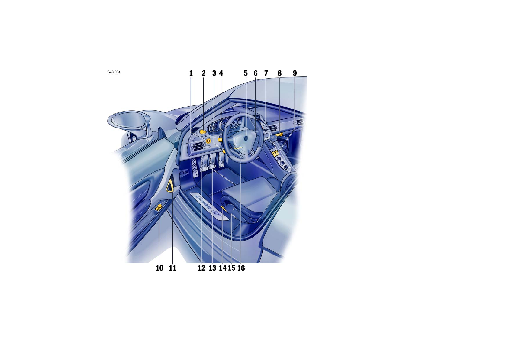
1 Ignition/starter switch with steering lock
2 Light switch
3 Operating lever for on-board computer
4 Turn signal/headlight dimmer,
flasher lever
5Horn
6 Windshield wiper/washer lever
7 Emergency flasher switch
8 Glove compartment with socket
9 Power window switch
10 Door mirror control
11 Inner door handle
12 Diagnostic socket
13 Seat adjustment
14 Parking brake
15 Front lid release,
engine compartment lid release
16 Steering-wheel adjustment
Controls, Instruments 17
Page 18
Never invite car theft!
An unlocked car with the key in the ignition lock
invites car theft.
A steering wheel lock and a gong alarm are standard equipment in your Porsche.
The gong alarm will sound if you open the driver’s
door while the key is still in the ignition lock. It is
your reminder to pull the key out of the ignition
lock and to lock the doors.
Warning!
Any uncontrolled movement of the vehicle
may result in serious personal injury and
property damage.
Never leave your vehicle unattended with the
key in the ignition lock, especially if children
and/or pets are left unattended in the vehicle. They can operate power windows and
other controls. If the engine is left running,
they may accidentally engage the shift lever.
f Always remove the ignition key.
f Always set the parking brake.
f Lock the doors with the key or with the remote
control.
Warning!
Risk of a serious accident.
The steering column will lock if you remove
the key while you are driving or as the car is
rolling to a stop. You will not be able to steer
the car.
f Never remove the key from the steering lock
while you are driving.
To protect your vehicle and your possessions
from theft, you should always proceed as
follows when leaving your vehicle:
f Close windows.
f Install the removable roof panels.
f Remove ignition key.
f Engage steering lock.
f Lock glove compartment.
f Remove valuables (e.g. car documents, tele-
phone, house keys) from the car.
f Lock doors.
18 Controls, Instruments
Page 19

Keys
f Please observe the chapter “ALARM SYSTEM,
INFRARED PASSENGER COMPARTMENT MONITORING” on Page 24.
f Please observe the chapter “CENTRAL LOCK-
ING” on Page 22.
Two main keys and one spare key are supplied
with your Porsche.
These keys operate all the locks on your vehicle.
f Be careful with your car keys: do not part with
them except under exceptional circumstances.
f To avoid battery run-down, always remove the
ignition key from the ignition lock.
Replacement keys
Replacement car keys can be obtained only from
your authorized Porsche dealer, and this can
sometimes be very time-consuming.
You should therefore always keep the spare key on
your person.
Keep it in a safe place (e.g. wallet), but under no
circumstances in or on the vehicle.
The key codes of new keys have to be “reported”
to the car control unit by your authorized Porsche
dealer.
The key grip of the spare key can be exchanged
for a main-key grip.
Disabling key codes
If a key is lost, the key codes can be disabled by
an authorized Porsche dealer.
All the remaining car keys are required for this purpose.
Disabling the code ensures that the car can be
started only using authorized keys.
Note
f Please note that the other locks can still be
opened with the disabled key.
Immobilizer
There is a transponder (an electronic component)
in the key grip, containing a stored code.
When the ignition is switched on, the ignition lock
checks the code.
The immobilizer can be deactivated and the engine started only using an authorized ignition key.
Switching off the immobilizer
f Insert the ignition key into the ignition lock.
If the ignition was on longer than 2 minutes without
the engine starting, the engine starts with a short
delay.
Switching on the immobilizer
f Withdraw the ignition key.
Controls, Instruments 19
Page 20
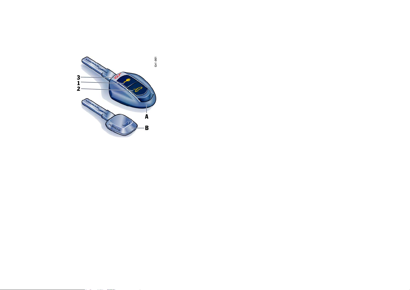
A -Main key
1 - Central locking button
2 - Front lid button
3 - Light-emitting diode
B - Spare key
Key with Radio Remote Control
Unlocking vehicle
f Briefly press button 1.
Unlocking front lid
f Press button 2 for approx. two seconds.
If the vehicle was locked, it is unlocked simultaneously with the front lid.
The vehicle will be locked again approx.
15 seconds after the front lid is closed if none of
the doors was opened.
Note
Your authorized Porsche dealer can program further types of unlocking.
Typ e 1
The relocking time of the doors can be adjusted to
suit your individual requirements:
4 - 120 seconds.
Typ e 2
The doors stay locked when the front lid is unlocked.
The remote-control standby function
switches off after 5 days
If the vehicle is not started or unlocked with the remote control within five days, the remote control
standby function is switched off (to prevent discharging of the vehicle battery).
1. In this case, unlock the driver’s door with the
key at the door lock.
Leave the door closed in order to prevent the
alarm system from being triggered.
2. Press button 1 on the remote control.
The remote control is now activated again.
Locking vehicle
f Briefly press button 1.
20 Controls, Instruments
Page 21
Doors
If the door windows are closed, they will be automatically opened by a few millimeters when the
doors are opened and, when the doors are closed,
they will be closed again. This makes it easier to
open and close the doors and protects the window
seals.
f Therefore, you should pull the door handle
slowly so that the door window can be lowered
before the door is opened.
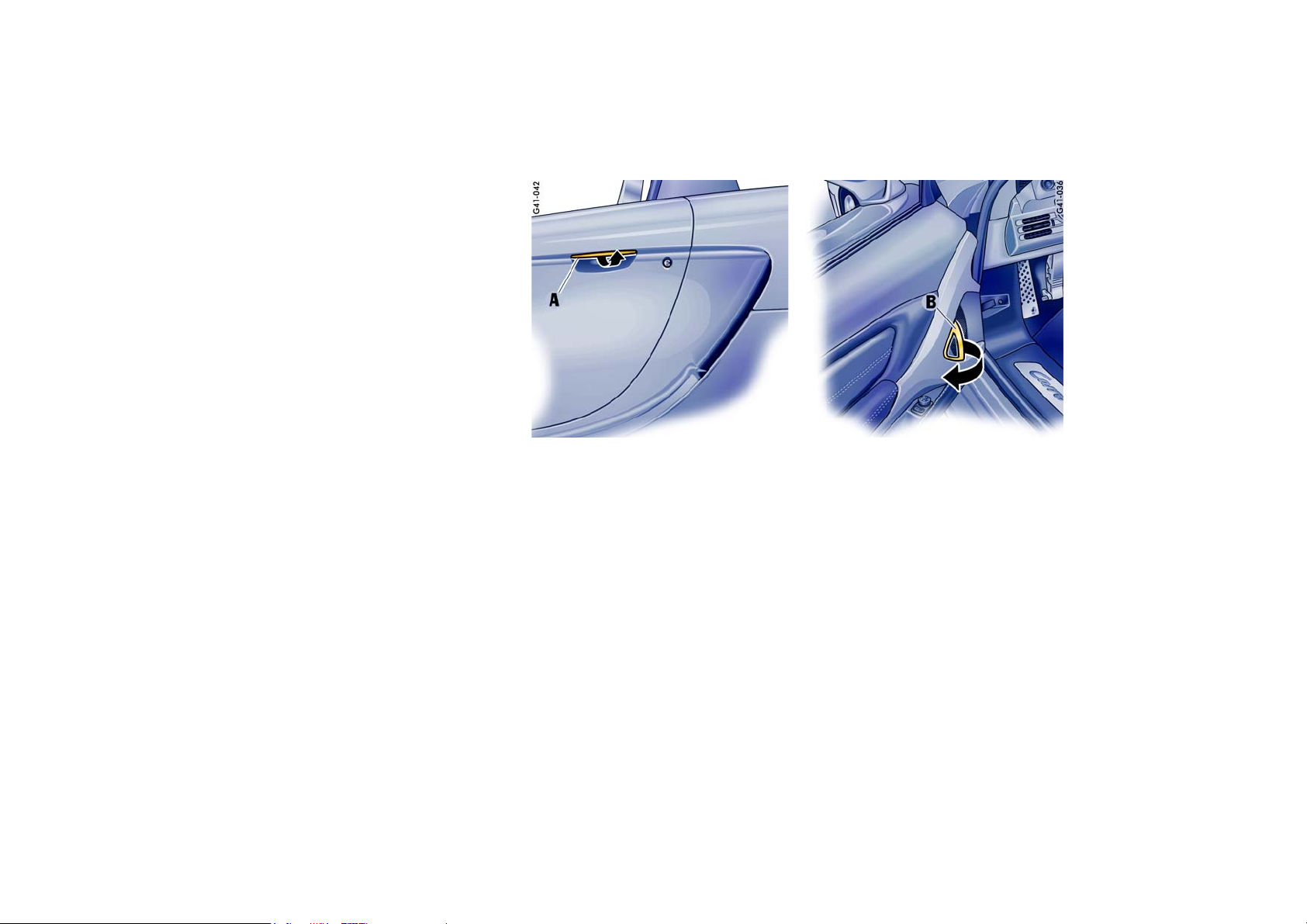
Opening unlocked doors from outside
f Slowly pull door handle A.
Opening unlocked doors from inside
f Slowly pull door handle B.
Opening locked doors from inside
f Slowly pull door handle B twice.
Please observe the chapter “LOCKING CONDITIONS” on Page 22.
Controls, Instruments 21
Page 22

Central Locking
USA: FCC ID LXPRKY 116;
FCC ID LXPVIM 145
Canada: TxF 315P 2255 102 275;
RxF 315P 2255 102 276 A
This device complies with:
Part 15 of the FCC Rules
RSS-210 of Industry Canada.
Operation of this device is subject to the following
two conditions:
– It may not cause harmful interference, and
– it must accept any interference received
including interference that may cause
undesired operation.
Note
The manufacturer is not responsible for any radio
or TV interference caused by unauthorized modifications to this equipment.
Such modification could void the user’s authority
to operate this equipment.
f Please observe the chapter “LOAD SWITCH-
OFF AFTER TWO HOURS OR FIVE DAYS” on
Page 156.
f Please observe the chapter “POWER WIN-
DOWS” on Page 26.
Both car doors and the filler flap can be centrally
unlocked or locked with the remote control.
The vehicle cannot be locked if the driver’s door is
not completely closed.
A short signal from the alarm horn will draw
your attention to the fact that the following
components are not completely closed when you
try to lock the vehicle:
– Passenger’s door
– Front lid
– Engine compartment lid
– Glove compartment
Note
Unlocking the vehicle by using the key in the door
lock and opening the door may activate the alarm
system within 10 seconds.
Automatic relocking
If the car is unlocked by remote control and none
of the car doors is opened within approx.
60 seconds, automatic relocking takes place.
This relocking time can be adapted to your individual requirements (4 - 120 seconds) by an authorized Porsche dealer.
Locking conditions
f Lock car once.
The doors cannot be opened from the outside.
Alarm system and infrared passenger compartment monitoring are switched on.
If a person or animal remains in the vehicle:
f Quickly lock car twice.
The doors cannot be opened from the outside.
The infrared passenger compartment monitoring is switched off.
Unlocking the door with the inner door
handle
Any person remaining in the locked car can open
the door with the inner door handle:
1. Pull inner door handle once to unlock door
lock.
2. Pull inner door handle again to open door.
Note
f Inform any person remaining in the car that the
alarm system will be triggered if the door is
opened.
22 Controls, Instruments
Page 23
Emergency operation – opening
f Unlock the driver’s door with the key at the
door lock.
Open the door and switch the ignition on within
10 seconds in order to prevent the alarm system from being triggered.
Emergency operation – closing
f Quickly turn the key in the driver’s door lock to
the lock position three times in succession.
If there is a defect in the central locking system, all functioning elements of the central
locking system will be locked.
The alarm system is switched on.
The infrared passenger compartment monitoring system is switched off.
The fault should be remedied immediately at an
authorized Porsche dealer.
Indication by emergency flasher and
alarm horn
If the remote control is used for unlocking or
locking, a response is provided by the emergency
flasher:
– Unlocking – single flash.
– Locking – double flash.
– Locking twice – continuous illumination for ap-
prox. 2 seconds and short alarm-horn signal.
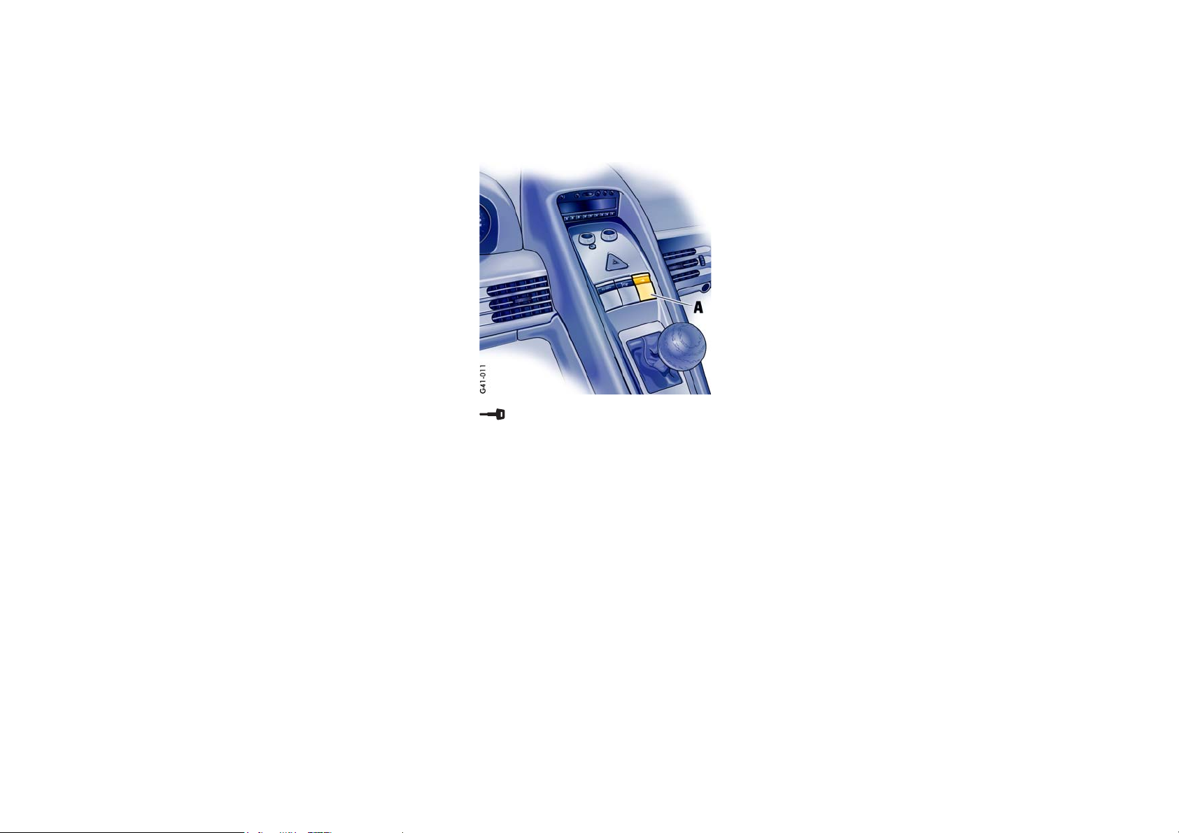
Locking
f Press the key symbol on the switch.
With the ignition switched on, the key symbol
lights up red.
Unlocking
f Press the lower half of the switch.
The red key symbol goes out.
If the doors were locked with the central locking
switch, they can be opened by pulling the inner
door handle:
1. Pull inner door handle once to unlock door
lock.
2. Pull inner door handle again to open door.
f f f
Central locking switch
The central locking switch A on the center console
lets you lock and unlock both doors electrically.
Note
If the doors are locked with the key or remote control, they can not be opened by pressing the central locking switch.
Controls, Instruments 23
Page 24
Automatic door locking
Your authorized Porsche dealer can program diverse types of automatic door locking in the control unit of the central locking system:
Type 1
Doors lock automatically when the ignition is
switched on.
Type 2
Doors lock automatically when a speed of
3 - 6 mph (5 - 10 km/h) is exceeded.
Type 3
Doors lock automatically when the ignition is
switched on. If doors are opened with the engine
running, they lock again automatically when a
speed of 3 - 6 mph (5 - 10 km/h) is exceeded.
Type 4
The doors do not lock automatically.
Note
Automatically locked doors can be unlocked with
the central locking button or opened by pulling on
the inside door handle twice.
Warning!
In an emergency situation where you need to
exit the car through an automatically locked
door, remember the following procedure to
open the door.
f Unlock the doors by pressing the central lock-
ing button or
f pull the inside door handle twice to open the
door.
Fault indication
A double horn signal during locking indicates a
defect in the central locking or alarm system.
Have the defect remedied at an authorized
Porsche dealer.
Overload protection
If the central locking system is operated more
than ten times within a minute, further operation is
blocked for 30 seconds.
Alarm System,
Infrared Passenger Compartment
Monitoring
The alarm system and infrared passenger compartment monitoring system are switched on
when the doors are locked with the key or remote
control.
f Please observe the chapter “CENTRAL LOCK-
ING” on Page 22.
24 Controls, Instruments
Unlocking the vehicle by using the key in the
door lock and opening the door may activate
the alarm system within 10 seconds.
Page 25

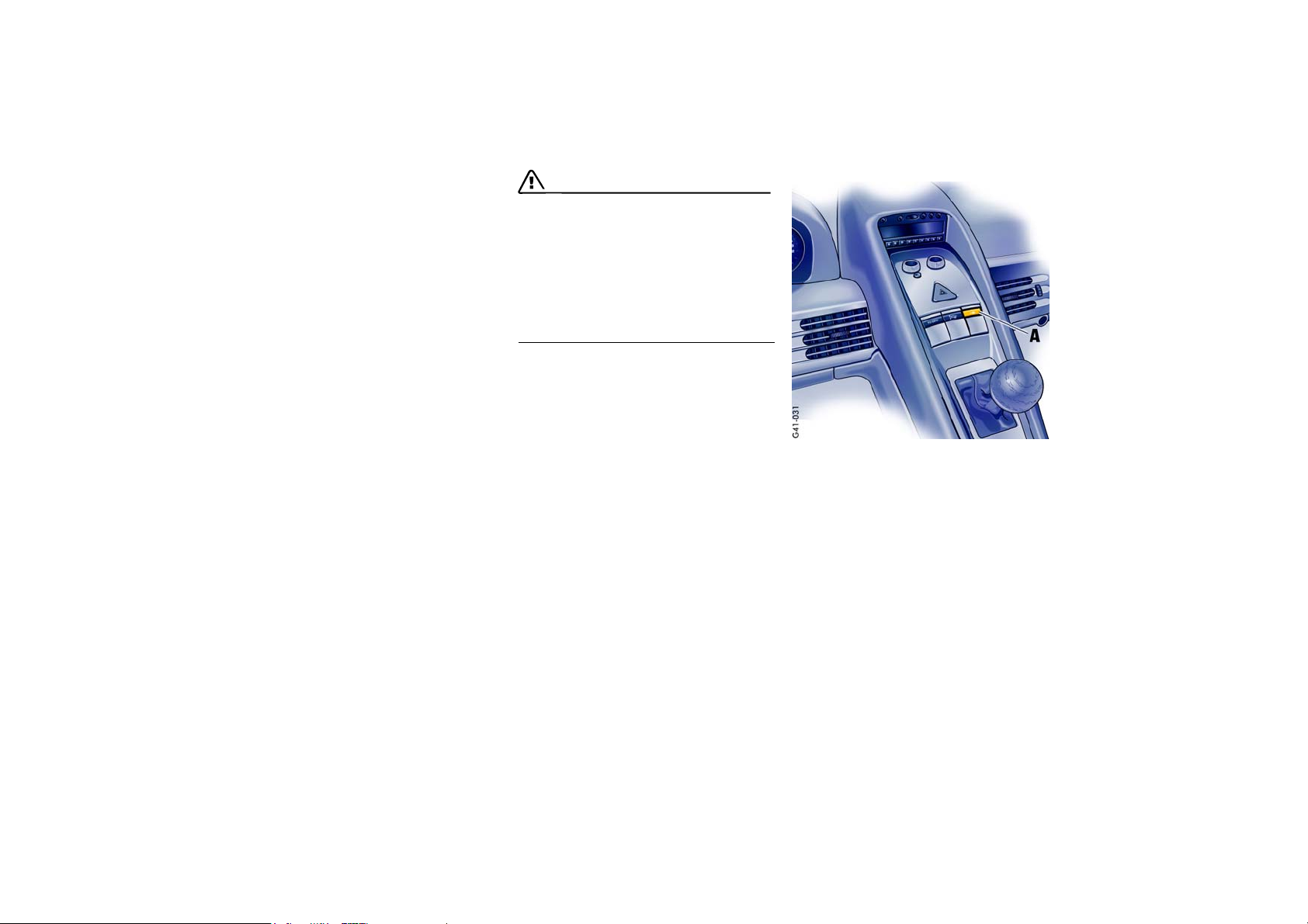
Function indication
If the alarm system is activated, key symbol A in
the central locking switch flashes.
If, after locking, the key symbol does not flash or,
after ten seconds, it emits double flashes, then
not all alarm contacts are closed.
Additionally, a brief horn signal sounds.
When the doors are unlocked, the alarm system
and infrared passenger compartment monitoring
system are switched off and the key symbol goes
off.
When the alarm is armed, the following
areas are monitored
– Doors
– Front lid
– Engine compartment lid
– Glove compartment
– Passenger compartment
If one of these alarm contacts is interrupted, the
alarm horn sounds for approximately 3 minutes.
Additionally, the emergency flasher and the passenger compartment light flash for approximately
five minutes.
When the alarm is triggered, the key symbol A
changes over to double flashes.
In order not to limit the action range of the infrared
passenger compartment monitoring system:
f Move sun visors to one of the final positions.
Deactivating the infrared passenger
compartment monitoring system for one
locking process
If a person or animal remains in the car while it is
locked, the infrared passenger compartment monitoring system must be switched off.
f Quickly lock car twice.
The doors are locked but can be opened from
the inside:
1. Pull inner door handle once to unlock door
lock.
2. Pull inner door handle again to open door.
Note
f Inform any person remaining in the car that the
alarm system will be triggered if the door is
opened.
Fault indication
A double horn signal during locking indicates a
defect in the central locking or alarm system.
f Have the defect remedied at an authorized
Porsche dealer.
Controls, Instruments 25
Page 26
Power Windows
Warning!
Risk of injury when the door windows close.
This applies especially if the windows are
closed with the comfort function, because
with this function the window goes up automatically.
f Make sure nobody can be injured when the
windows close.
f Remove the ignition key to shut off power to
the window switches when the vehicle is not
attended by a responsible person. Uninformed
persons could injure themselves by operating
the power windows.
f Do not leave children in the car unattended.
Risk of an accident.
f Do not put anything on or near the windows
that may interfere with the driver’s vision.
Readiness for operation of power windows
– With engine running or
– in ignition key position 1 or
– with door closed and ignition key withdrawn:
only until first opening of the door.
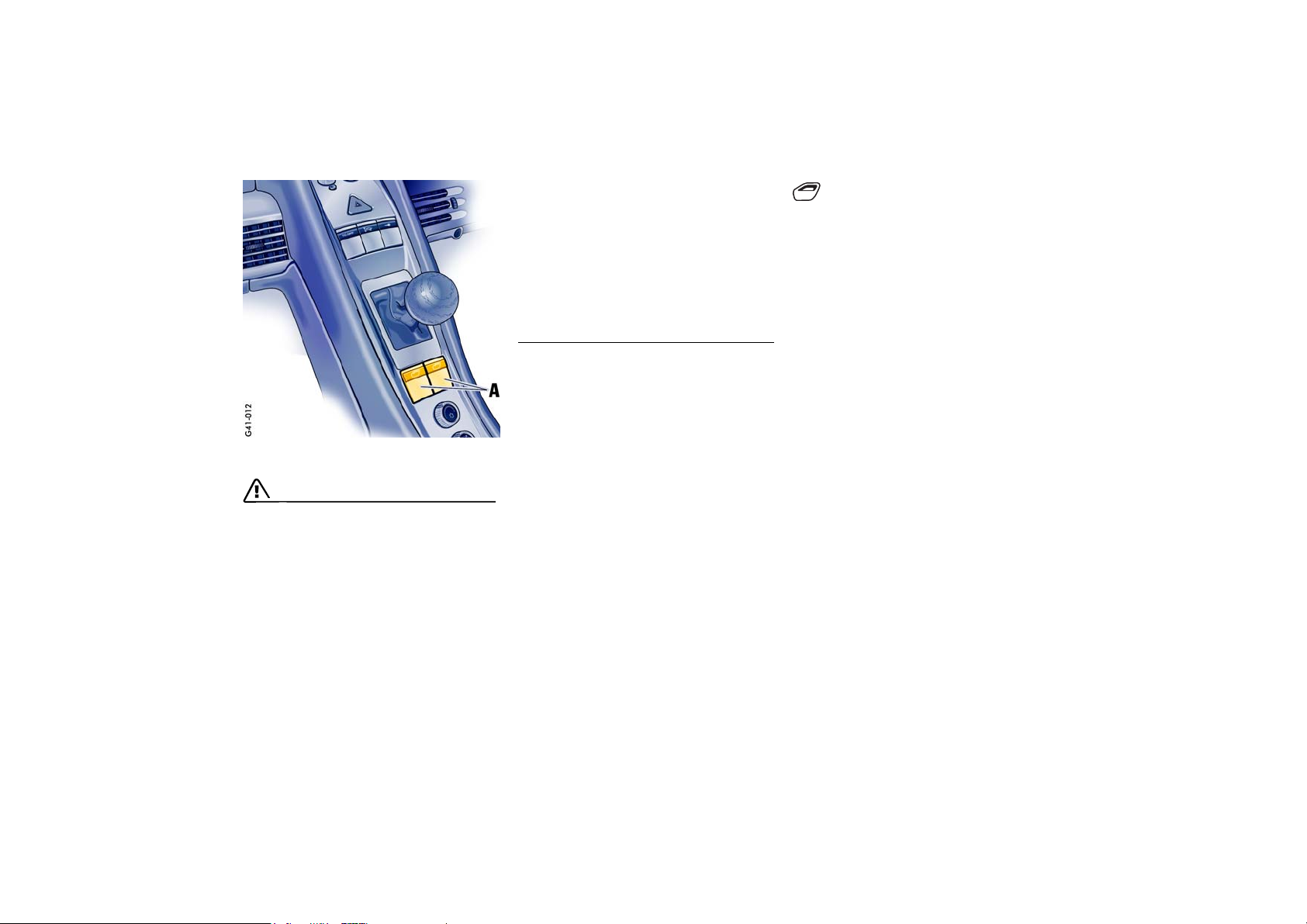
Opening windows
f Press the lower half of the rocker switch A until
the window has reached the desired position.
One-touch operation
f Press the lower half of the rocker switch A
briefly.
Window moves to its final position.
Press again to stop the window in the desired
position.
Comfort function when unlocking the vehicle
f Unlock car with the remote control.
Hold car key in door lock in the unlocking direction until the windows have lowered to the desired position.
26 Controls, Instruments
Page 27

Closing windows
f Press the upper half of the rocker switch A un-
til the window has reached the desired position.
One-touch operation
f Press the upper half of the rocker switch A
briefly.
Window moves to its final position.
Press again to stop the window in the desired
position.
Comfort function when locking the vehicle at
the door lock
f Hold car key in door lock in the locking direc-
tion until the windows have closed to the desired position.
Anti-crushing protection
If a side window is blocked during closing, it will
stop and open again by about an inch.
Warning!
Risk of severe personal injuries.
If the rocker switch is pressed again within
10
seconds of the window being blocked, the
window will close with its full closing force.
Anti-crushing protection is disabled.
f Once the anti-crushing protection acts to stop
the window and opens it slightly, do not press
the rocker switch again within 10 seconds
without checking to make sure that nothing is
blocking the path of the window.
The window will close with full closing force.
One-touch operation is disabled for 10 seconds
after blockage of a side window.
Automatic window lowering
f Please observe the chapter “DOORS” on
Page 21.
Storing end position of the windows
If the battery is disconnected and reconnected,
the windows will not be raised automatically when
the door is closed.
1. Close the windows with the rocker switch
once.
2. Press upper half of rocker switch again to
store the end position of the windows in the
control unit.
Controls, Instruments 27
Page 28
Warning!
Risk of an accident.
f Do not put anything on or near the windows or
the mirrors that may interfere with the driver’s
vision.
Door mirror heating
The door mirror heating switches on automatically
at temperatures below approx. 37°F/3°C and
switches off automatically at temperatures above
37°F/3°C.
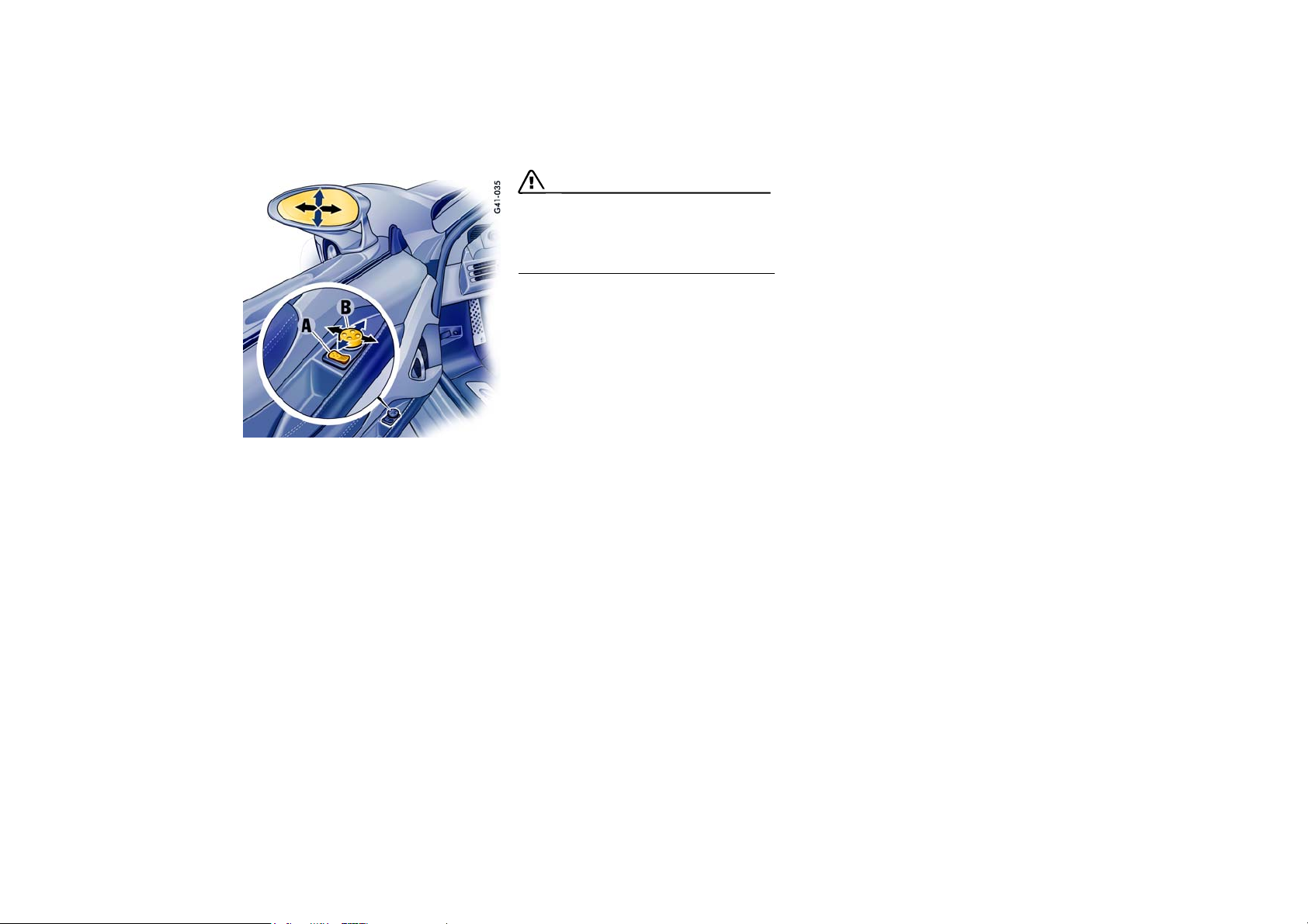
A - Selector switch, driver’s/passenger’s side
B - Mirror adjustment
Rear View Mirrors
Before driving the vehicle, adjust the outside and
inside mirrors.
It is important for safe driving that you have good
vision to the rear.
28 Controls, Instruments
Door mirrors
The mirror housing is hinged and can be folded flat
against the car to prevent damage in the tight
parking areas.
Adjusting
1. Select driver’s side or passenger’s side with
rocker switch A.
2. Move the door mirror glasses in the appropriate direction using the control switch B.
If the electrical adjustment facility fails
f Adjust mirror by pressing on the mirror face.
Switching on door mirror heating
Regardless of the outside temperature, the door
mirror heating is switched on together with the
defrost function of the windshield.
f Please observe the chapter “DEFROSTING
WINDSHIELD AND SIDE WINDOWS” on
Page 95.
Page 29
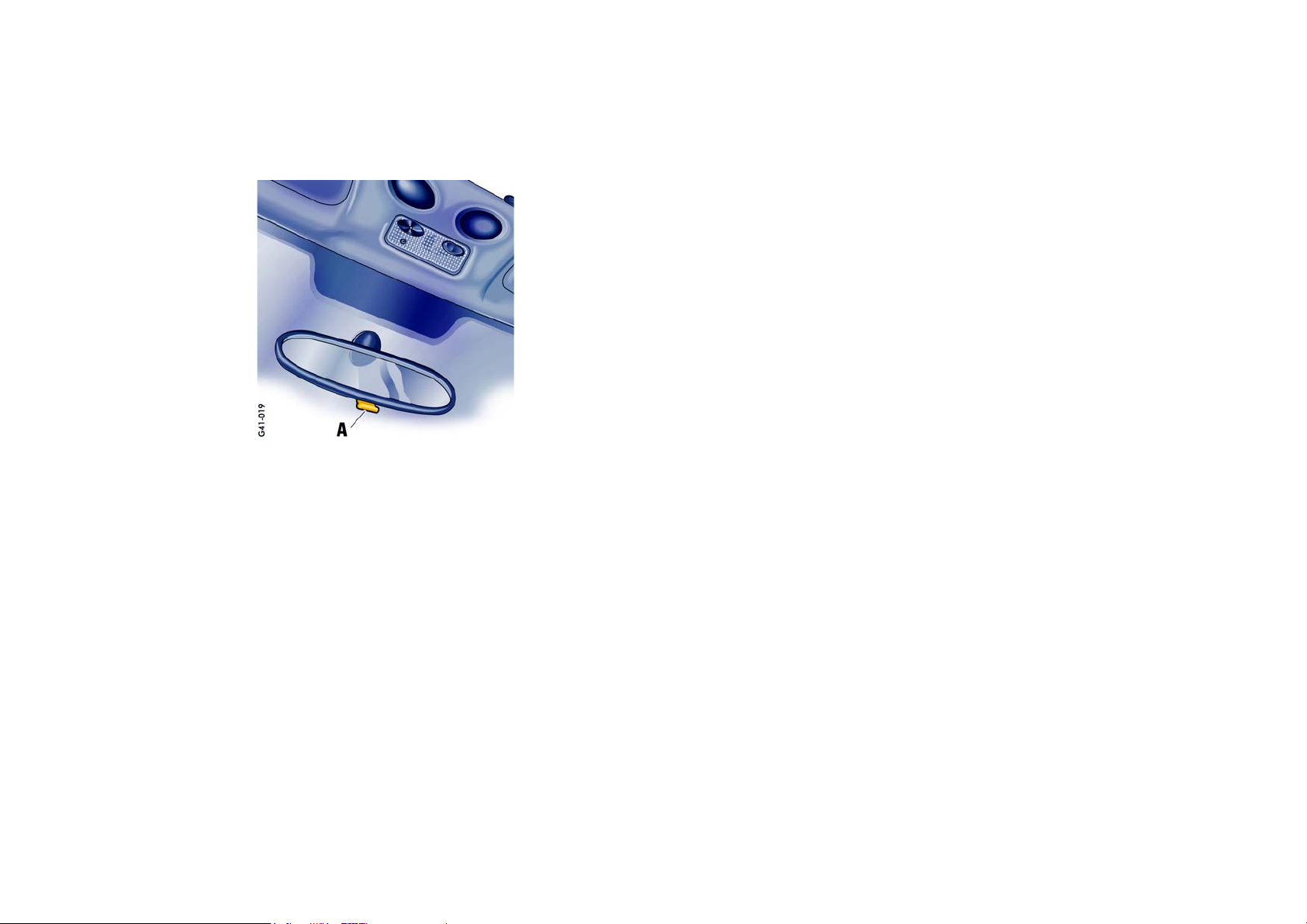
Inside mirror
When the mirror is being adjusted, the anti-glare
lever A must point forward.
Basic position: lever forward
Anti-glare position: lever back
Controls, Instruments 29
Page 30
Seat Adjustment
Warning!
The seat may move unexpectedly if you
attempt to adjust while driving. This could
cause sudden loss of control or personal injury.
f Do not adjust seats when the vehicle is in mo-
tion.
Seat position
A correct sitting position is important for safe and
fatigue-free driving.
We recommend the following procedure for
adjusting the driver’s seat to suit individual
requirements:
1. Adjust the seat until, with the accelerator pedal
fully depressed, your leg is straight but your
entire foot still rests on the accelerator pedal.
2. Grip the top half of the steering wheel.
Set the steering-wheel position so that your
arms are almost outstretched. However, your
shoulders must still rest on the backrest.
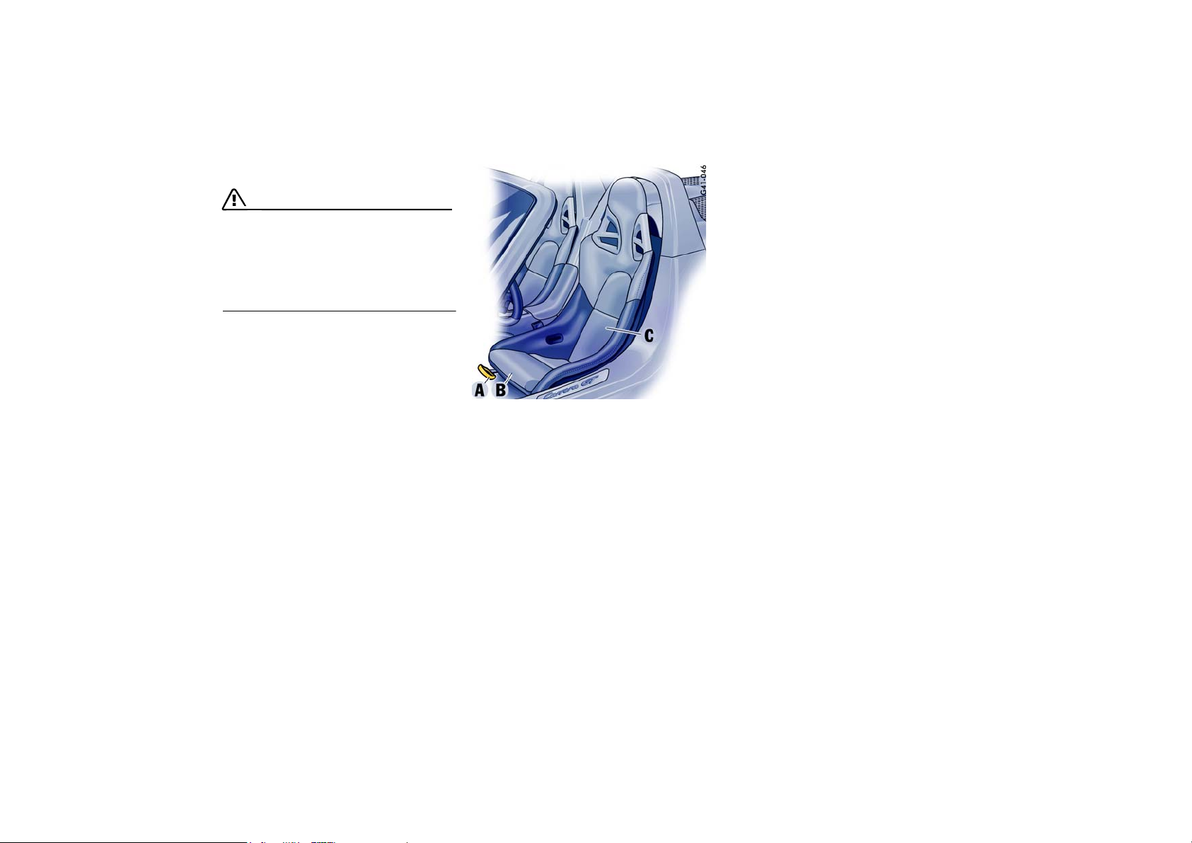
3. If necessary, correct the seat fore-and-aft
adjustment.
Fore and aft
f Raise locking lever A.
Move seat to desired position and release
lever.
Ensure that the seat engages correctly.
Seat height adjustment
It is possible to adjust the height of both seats.
As the seat mounting must be loosened to adjust
the height, this must only be done by an authorized Porsche dealer.
Thigh support area
Changing the front seat cushion B can adjust the
height of the thigh support area.
Lumbar cushion
(pelvis and spinal column support)
There is a height-adjustable lumbar cushion below
the back cushion.
f Carefully loosen the back cushion C from the
bottom upward (Velcro fastening strip).
f Loosen the lumbar cushion (Velcro fastening
strip) and tighten in the desired position.
f Carefully press the back cushion C into the
correct position from the top downward.
30 Controls, Instruments
Page 31

Steering Wheel Adjustment
Warning!
Risk of accident.
The steering wheel may move further than
desired if you attempt to adjust it when driving.
You may lose control of the vehicle.
f Do not adjust the steering wheel when driving.
Longitudinal adjustment
1. Push locking lever downwards.
2. Adjust steering wheel to your seat position by
moving the steering wheel longitudinally.
3. Swivel locking lever back until you feel it
engage.
If necessary, move steering wheel slightly longitudinally, to ensure engagement.
Controls, Instruments 31
Page 32

Safety Belts
Warning!
Always make sure your and your passenger’s
safety belts are properly fastened while the
vehicle is in motion.
Failure to follow safety belt warnings may result in serious personal injury.
f For your and your passenger’s protection, use
safety belts at all times while the vehicle is in
motion.
Proper wearing of safety belts
f Safety belts must be positioned on the body so
as to restrain the upper body and lap from sliding forward. Improperly positioned safety belts
can cause serious personal injury in case of an
accident.
f The shoulder belt should always rest on your
upper body. The shoulder belt should never be
worn behind your back or under your arm.
f For maximum effectiveness, the lap belt
should be worn low across the hips.
f Pregnant women should position the belt as
low as possible across the pelvis. Make sure it
is not pressing against the abdomen.
f Belts should not be worn twisted.
f Do not wear belts over rigid or breakable ob-
jects in or on your clothing, such as eye glasses, pens, keys, etc. as these may cause injury.
f Several layers of heavy clothing may interfere
with proper positioning of belts.
f Belts must not rub against sharp objects or
damage may occur to the belt.
f Two occupants should never share the same
belt at the same time.
Care and maintenance
f Keep belt buckles free of any obstruction that
may prevent a secure locking.
f Belts that have been subjected to excessive
stretch forces in an accident must be inspected or replaced to ensure their continued effectiveness in restraining you.
The same applies to belt tensioner systems
which have been triggered.
In addition, the anchor points of the belts
should be checked.
f If safety belts do not work properly, see your
authorized Porsche dealer immediately.
f If the b el ts s ho w da mag e t o we bb ing , b ind in gs,
buckles or retractors, they should be replaced
to ensure safe operation.
f Do not modify or disassemble the safety belts
in your vehicle.
f The belts must be kept clean or the retractors
may not work properly.
Please observe the chapter “CAR CARE INSTRUCTIONS” on Page 135.
f Never bleach or dye safety belts.
f Do not allow safety belts to retract until they
are completely dry after cleaning or this may
cause damage to the belt.
Belt tensioner
Depending on the force of an impact, fastened
safety belts are tightened in an accident.
The belt tensioners are triggered in:
– Front and rear impacts
The belt tensioners are not triggered in:
– Side impacts
– Vehicle overturning
Note
The belt tensioner system can be triggered only
once; the system must be replaced afterwards.
Work may be performed on the belt-tensioner system only by an authorized Porsche dealer.
Smoke is released when the belt tensioners are
triggered. This does not indicate a fire in the
vehicle.
32 Controls, Instruments
Page 33

Safety Belt Warning System
Child Restraint Systems
An audio-visual warning system is interconnected with the driver’s safety belt.
Every time the ignition is turned on, the gong will
sound for about 6 seconds to remind driver and
passenger to buckle up.
In addition, the gong will sound if vehicle speed
exceeds 6 mph/10 km/h.
The safety belt warning lights in the instrument
panel and on-board computer will go off as soon
as the driver has buckled up.
Inertia reel retractor
The combination lap/shoulder belt with inertia reel
locking mechanism automatically adjusts to your
si ze an d mov ement s as long as the pull on th e bel t
is slow.
Rapid deceleration during hard braking or a collision locks the belt. The belt will also lock when you
drive up or down a steep hill or in a sharp curve,
otherwise, the shoulder belt will not inhibit your
upper body movement.
f Assume a comfortable sitting position.
The shoulder belt should always rest on your
upper body. The shoulder belt should never be
worn behind your back or under your arm.
f To fasten, grasp belt and pull the belt in a con-
tinuous slow motion across your chest and lap.
Danger!
Risk of death or serious injury.
f Do not allow children under the age of 12 to sit
in this car. The Carrera GT has frontal airbags
and does not have an airbag deactivation system. Children in child seat or booster seat are
at risk for serious personal injuries or death if
the front airbag deploys.
f Do not install the Porsche child seat on your
passenger seat.
f Insert belt tongue into buckle on inboard side
of seat. Push down until it securely locks with
an audible click. Pull the belt to check.
f Pull shoulder section to make sure belt fits
snugly across the pelvis.
f Belts should fit snugly across the pelvis and
chest. Make sure there is no slack in the belt.
f To unfasten belt, push in release button (ar-
row) on buckle. Belt tongue will spring out of
buckle.
f To release a latched belt, lean back to take the
body pressure off the belt.
f To store lap/shoulder belt, allow the belt to re-
tract as you guide the latch to its stowed position.
Controls, Instruments 33
Page 34

Airbag Systems
The Airbags in combination with the safety belts
makes up a safety system which offers the driver
and the passenger the greatest known protection
from injuries in case of accident.
Even if your vehicle is equipped with airbags, the
safety belts must be worn at all times, because the front airbag system is only actuated by
frontal collisions with an impact of sufficient
severity.
Below the actuation threshold of the airbag system, and during types of collisions which do not
cause the actuation of the system, the safety belts
provide the primary protection to the occupants
when correctly worn.
Therefore, all persons within the vehicle
must always wear safety belts (in many states,
state law requires the use of safety belts).
f Please observe the chapter “SAFETY BELTS”
on Page 32.
The front airbags are located behind the padded
steering wheel panel on the driver’s side and on
the passenger’s side in the dashboard.
The side airbags are installed in the doors.
Function
The front airbags are triggered during a frontal
collision of sufficient force.
In the event of a side impact of corresponding
force, the side airbag on the impact side is triggered.
The inflation process generates the amount of gas
required to fill the airbags at the necessary pressure in fractions of a second.
Airbags protect the face and upper body, while
simultaneously damping the motion of the driver
and passenger in the impact direction in the event
of a frontal impact or side impact.
Danger!
To provide optimal occupant protection, airbags must inflate at very high speed.
If you are not wearing your safety belt or are
too close to the airbag when its deployed, inflating airbags can result in serious personal
injury or death.
f Make sure there are no people, animals or ob-
jects between the driver or passenger and the
area into which the airbag inflates.
f Sit bac k as far from the da shboard or stee ri ng
wheel as is practical, while still maintaining full
vehicle control.
f Do not lean against the inside of the doors.
f Always hold the steering wheel by the outer
rim.
Never rest your hands on the airbag panel.
f Never transport heavy or sharp objects on or
in front of the passenger seat.
f Give your passenger all of the information in
this chapter.
f No changes must be made to the wiring or
components of the airbag system.
34 Controls, Instruments
Page 35

f Do not add any additional coverings or stickers
to the steering wheel or in the area of the passenger airbag and side airbags. Doing so may
adversely affect the functioning of the airbag
system or cause harm to the occupants if the
airbag system should deploy.
f Do not undertake any wiring for electrical ac-
cessory equipment in the vicinity of the airbag
wiring harnesses. Doing so may disable the
airbag system or cause inflation.
f If the warning light comes on, the airbag sys-
tem should be repaired immediately by your
authorized Porsche dealer.
Note
Airbag components (e.g. steering wheel, door
trim) may be disassembled only by an authorized
Porsche dealer.
When disposing of a used airbag unit, our safety
instructions must be followed. These instructions
can be obtained at any authorized Porsche dealer.
Warning light
The central triggering unit monitors the operational readiness of the airbag system and the warning
light.
Any malfunctions that may occur will be indicated
by the warning lights in the instrument panel and
on-board computer.
f In the following cases you should immedi-
ately consult an authorized Porsche dealer in order to assure the airbag system is
functioning properly:
– Illumination of the airbag warning light during
travel or repeated illumination longer than 5
seconds after the ignition circuit is turned on.
– Illumination fails to light up during ignition
circuit activation.
Airbag maintenance
In order to ensure long-term functioning, the airbag system must be inspected by an authorized
Porsche dealer after 4, 8 and 10 years from the
date of manufacture shown on the safety compliance sticker, and every 2 years thereafter.
Important information
If you sell your Porsche, notify the purchaser that
the vehicle is equipped with airbags, and refer
them to the chapter, “Airbag Systems”, in the owner’s manual (safety and disposal rules).
Further information on the airbag system can be
found on stickers at the sun visors, as well as on
all airbag components.
Child Restraint Systems
Danger!
Risk of death or serious injury.
f Do not allow children under the age of 12 to sit
in this car. The Carrera GT has frontal airbags
and does not have an airbag deactivation system. Children in child seat or booster seat are
at risk for serious personal injuries or death if
the front airbag deploys.
f Do not install the Porsche child seat on your
passenger seat.
Controls, Instruments 35
Page 36

Clutch Pedal
The clutch pedal must be depressed fully
before the starter will engage.
Warning!
Risk of an accident.
f Always check the movement of the clutch ped-
al before driving and make sure that it is not
obstructed by a floor mat or any other object.
To avoid damage to the clutch and transmission:
f Always depress the clutch pedal fully when
changing gears.
f Do not hold the car on a steep grade with the
clutch pedal partially depressed.
Should the free travel of the clutch pedal suddenly
become larger, it could mean a malfunction of the
clutch.
f See your Porsche dealer for correction.
Parking Brake
Parking brake force is mechanically transferred to
the rear wheels by means of cables.
f Use the parking brake only after the vehicle
has come to a full stop.
Setting the parking brake
f Pull the lever all the way up (arrow).
With the ignition on, the parking brake warning
lights in the instrument panel and on-board
computer will come on if the lever is even
slightly raised. A firm pull upward is required to
properly engage the parking brake.
If the brake is not fully set, the vehicle may roll
without control.
f Move the gearshift lever to reverse or first
gear.
f Before exiting the vehicle, make sure that the
parking brake is fully set and the vehicle is not
moving at all.
Danger!
Risk of serious personal injury or death. A
partially engaged parking brake may allow
the vehicle to roll, causing serious personal
injury or death to any person in its path.
f Engage the parking brake fully.
f Before exiting the vehicle, make sure that the
parking brake is fully set and the vehicle is not
moving at all.
Releasing the parking brake
36 Controls, Instruments
f Pull the lever slightly up as you depress the re-
lease button A, and then push the lever all the
way down.
Page 37

Parking brake warning light USA
Parking brake warning light
Canada
The warning lights in the instrument panel and onboard computer will go out after the parking brake
is fully released.
The warning lights are not an indicator that the
parking brake is fully set; it is only intended to be
a warning to release the parking brake before
driving the car.
Caution!
A partially engaged brake will overheat the
rear brakes, reduce their effectiveness and
cause excessive wear.
f Release the parking brake fully.
f When parking your car, always set the parking
brake by pulling the lever all the way up.
f Move the gearshift lever to reverse or first
gear.
f On hills also turn the front wheels towards the
curb.
Brakes
f Please observe the chapter “AERODYNAMIC
COMPONENTS” on Page 9.
f Make it a habit to check the operation of your
brakes before driving.
Keep in mind that the braking distance increases
very rapidly as the speed increases. At 60 mph or
100 km/h, for example, it is not twice but four
times longer than 30 mph or 50 km/h. Tire traction is also less effective when the roads are wet
or slippery.
f Therefore, always maintain a safe distance
from the car in front of you.
Brake system function
Your Porsche is equipped with a power assisted
hydraulic dual circuit brake system with disc
brakes at the front and rear.
Both circuits function independently. One brake
circuit operates the front and the other operates
the rear.
If one brake circuit has failed, the other will still operate. However, you will notice an increased pedal
travel when you apply the brakes.
Failure of one brake circuit will cause the stopping
distance to increase.
Warning!
Risk of an accident.
In the unlikely event of hydraulic failure of
one brake circuit:
f Push the brake pedal down firmly and hold it in
that position.
A mechanical linkage activates the second circuit, and you will be able to bring the vehicle to
a stop.
f After bringing your vehicle to a complete stop,
avoid driving the vehicle and instead have it
towed to the nearest authorized Porsche dealer for repair.
f f f
Controls, Instruments 37
Page 38

Brake warning light USA
Brake warning light Canada
If the warning lights in the instrument panel and onboard computer go on while driving, the brake fluid level may be too low, or (if the brake pedal travel has increased) one of the two brake circuits
may have failed.
A greater braking pressure will be required, stopping distances will be longer and the braking behavior will change, particularly in curves.
With correctly adjusted brakes, and a correctly
working brake system, the pedal travel to the
point of brake actuation should be approximately
1-3/16 in to 1-9/16 in or 30 to 40 mm.
Whenever the brake pedal travel exceeds this distance, have the brake system checked.
Brake booster warning
The brake booster is monitored, in addition to the
brake fluid level.
If the brake fluid warning lamp lights up after
starting the engine, wait to drive until the required
pressure for the brake booster is established and
the warning light goes out.
If the brake fluid warning lamp in the instrument
panel does not go out, there could be a defect in
the brake booster.
Warning!
Risk of accident due to altered braking
behavior.
f Adjust your speed accordingly for longer
braking distances, higher required pedal
pressures, and altered braking behavior.
f Drive carefully to an authorized Porsche deal-
er. The brake system should be repaired immediatlely.
Brake pedal
Warning!
Risk of an accident.
Any obstruction of the brake pedal could
increase the stopping distance.
f Always check the movement of the brake ped-
al before driving and make sure that it is not
obstructed by a floor mat or any other object.
Note
In case one of the two brake circuits fails, increased pedal travel is required to bring your
vehicle to a full stop.
Warning!
To avoid overheating and premature wear of
the brakes:
f Before descending a steep grade, reduce
speed and shift the transmission into a lower
gear to control speed.
f Do not “ride the brakes” by resting your foot on
the pedal when not intending to apply brake
pressure.
f Do not hold the pedal down too long or too
often.
This could cause the brakes to get hot and not
function properly.
38 Controls, Instruments
Page 39

Brake booster
Brake wear
Brake pads
The brake booster assists braking only when
the engine is running.
When the car is moving while the engine is not running, or if the brake booster is defective, more
pressure on the brake pedal is required to bring
the car to a stop.
Moisture or road salt
Moisture or road salt on brakes affects braking.
When the vehicle is driven on salted roads for extended periods, the brakes should be washed
down thoroughly about every 2 weeks.
Brakes will dry after a few cautious brake applications.
Warning!
Driving through water may reduce the traction.
Moisture on brakes from road water, car
wash, or coating of road salt may affect
braking efficiency.
f Cautiously apply brakes to test brakes after
such exposures.
Your car has excellent brakes, but they are still
subject to wear. The rate at which they wear depends on how the brakes are used.
f Have the brake system inspected at the
intervals recommended in your Maintenance
Booklet.
Warning light USA
Warning light Canada
If the warning lights in the instrument panel and onboard computer stay on when the engine is running or come on while driving, the brake pads are
worn, excessively.
f Do not continue to operate the vehicle.
Have your authorized Porsche dealer inspect
or replace the brake pads.
Wear on the brake pads and brake discs depends
to a great extent on the driving style and the conditions of use and therefore cannot be expressed
in actual miles on the road.
The high-performance brake system is designed
for optimal braking effect at all speeds and temperatures.
Certain speeds, braking forces and ambient
conditions (such as temperature and humidity)
may cause “brake noises”.
New brake pads or linings
New brake pads and brake discs have to be “broken in”, and therefore only attain optimal friction
when the car has covered several hundred miles
or km.
The slightly reduced braking ability must be compensated for by pressing the brake pedal harder.
This also applies whenever the brake pads and/or
brake discs are replaced.
Controls, Instruments 39
Page 40

ABS Brake System
(Antilock Brake System)
The ABS system represents a major contribution
to the enhancement of active safety in your vehicle. This system prevents the wheels from locking
in a panic stop on almost all road surfaces.
With the ABS system in your vehicle, the
following areas are enhanced:
Steering, vehicle remains steerable under all
braking forces when ABS is engaged.
Good directional control, no swerving caused
by locking of wheels under braking conditions.
Shorter stopping distance, stopping distances
are usually reduced because controlled braking is
maximized.
Prevention of wheel lock up, no brake- induced
sliding and thus no localized tire wear from emergency braking.
The crucial advantage of the ABS system over a
conventional brake system is in the area of maintaining directional control and maneuverability of
the car in emergency situations during normal
driving, including panic braking in turns.
Warning!
The increased control that is provided should
not induce you to take greater risks with your
safety. The limits dictated by the laws of
physics cannot be overcome, even with ABS.
The risk of accidents due to inappropriate
speed cannot be reduced, even by the ABS.
The driver bears the responsibility for all
driving maneuvers.
f Adapt your driving style to the prevailing road
and weather conditions.
f Obey all traffic laws.
Other vehicles not equipped with the ABS
system may not be able to maintain control,
especially on wet or poor road surfaces and
thus may be more likely to impact you from
behind.
f To minimize that risk, use your ABS system to
increase your ability to maneuver to avoid dangerous situations and not merely to try to stop
in the shortest distance possible.
40 Controls, Instruments
Page 41

Operation of the ABS system
A wheel speed sensor is mounted to each of the
four wheels. If wheel lock-up of either of the front
wheels or the rear wheels is sensed during braking, the brake pressure is adjusted automatically
until the wheel no longer locks up.
The proper operation of ABS is perceived by the
driver as a pulsating brake pedal in conjunction
with audible noise and perhaps some vibration.
f If you experience these sensations while driv-
ing or a road surface with questionable traction, reduce vehicle speed appropriate for the
prevailing road conditions.
The functional readiness of all the main electrical
components of the ABS is checked by an
electronic monitoring system both before and
while you drive.
Warning light USA
Warning light Canada
When the ignition is switched on the ABS warning
light will light up while the system is electronically
interrogated and goes out when the engine is
started if the check is not yet complete.
If the ABS warning lamp fails to go out, this indicates that ABS has been deactivated due to a
fault. If the warning lights in the instrument panel
and on-board computer light up while you are driving, this indicates that a fault has occurred. In both
cases, normal braking, as in vehicles without ABS,
is still retained.
The ABS system should, however, be examined at
an authorized Porsche dealer immediately to prevent the occurrence of further faults.
f If the ABS system becomes inoperative, take
your vehicle to your authorized Porsche dealer
immediately.
Warning!
The control unit of the ABS brake system is
set for standard tire size. If non-standard
tires are installed, the control unit may misinterpret the speed of the vehicle, because of
the variant data it receives from the sensors
on the axles.
f Use only tire makes and types tested by
Porsche.
Controls, Instruments 41
Page 42

Traction Control (TC)
TC counteracts the spinning of the driven wheels
when moving off and accelerating.
Driving stability and traction are improved over the
entire speed range.
Warning!
The increased control that is provided should
not induce you to take greater risks with your
safety. The limits dictated by the laws of
physics cannot be overcome, even with TC.
The risk of accidents due to inappropriate
speed cannot be reduced, even by the TC.
The driver bears the responsibility for all
driving maneuvers.
f Adapt your driving style to the prevailing road
and weather conditions.
f Obey all traffic laws.
Readiness for operation
TC is switched on automatically every time you
start the engine.
Function
Engine torque control
When the wheel rotation speed of the front and
rear axles differs by more than a specified value
(spinning), this is detected by TC system and
engine output is automatically reduced.
Brake control
In addition to reducing engine power, TC brakes
the spinning drive wheels.
Simultaneous spinning of both drive wheels does
not result in brake intervention.
This means: driving stability is not monitored.
The events below inform the driver of TC control
operations and warn him to adapt his driving style
to the road conditions:
– The information light in the instrument panel
lights up
– Hydraulic noises can be heard
– Reduced engine power
Switching off Traction Control
f Press the “TC OFF” logo of the A button.
TC is switched off after a short delay.
With TC switched off, the TC OFF warning light
on the instrument panel lights up.
Note on operation
TC cannot be switched off during a controlled
braking process (information light on).
42 Controls, Instruments
Page 43

The TC should always be switched on during
“normal” driving. This is particularly the case
when the road is wet.
However, it can be of advantage to switch off TC
temporarily in exceptional situations:
– On a loose surface or in deep snow,
– When “rocking the vehicle free”,
– When using snow chains.
Switching on Traction Control again
f Press the “TC OFF” logo of the A button.
TC is switched on after a short delay.
Note on operation
TC cannot be switched on again during a
controlled braking process.
Information light
– The TC information light in the instrument
panel lights up for a lamp check when the ignition is switched on.
– The light indicates a control operation.
Warning light
– The warning light in the instrument panel lights
up for a lamp check when the ignition is
switched on.
– The light indicates that TC is deactivated.
– The lights in the instrument panel and in the on-
board computer indicate a defect.
The TC is out of order.
The fault should be remedied immediately at
an authorized Porsche dealer.
Towing
f Please observe the chapter “TOWING, RECOV-
ERY” on Page 172.
Checks on test stands
Handbrake tests on the brake test stand must
only be carried out with the ignition switched off.
Controls, Instruments 43
Page 44

Retractable rear wing
Warning!
Risk of accident.
If the rear wing does not extend, driving
stability will be adversely affected.
f Adapt your driving style and speed to the
changed driving conditions.
f Have the fault remedied at an authorized
Porsche dealer.
f Do not exceed the posted legal speed limit.
Serious injuries may occur from crushing
and pinching at all moving parts in the area
of the rear wing.
f Ensure that no one can be injured and no
objects can be jammed by the extension or
retraction of the rear wing.
Risk of damage to rear wing.
f Do not pull or push the vehicle using the rear
wing.
f Do not place objects on the rear wing.
Manual control
When the ignition is on, the rear wing can be extended and retracted manually using the button A
in the center console.
Extension
f Press upper half of the button briefly.
The rear wing extends to its final position.
Retraction
f Press and hold lower half of the button until the
rear wing has reached its final position.
Automatic control
The rear wing extends at approx. 75 mph/
120 km/h and retracts at approx. 50 mph/
80 km/h.
If high engine power is used over longer periods
of time, the retraction of the rear wing is
suppressed, so that when the car is driven in a
sporty manner, the rear wing is not constantly
extending and retracting.
When the vehicle is driven at moderates speeds
afterwards, the rear wing can remain extended for
up to 15 minutes, even after the vehicle is
parked.
If the vehicle is driven with even lower demands on
the engine, the rear wing will retract and extend
dependent on the speed.
If automatic control fails, the warning light illuminates. The rear wing must be extended manually
by pressing button A when the vehicle is
stationary.
Warning light
The warning light in the instrument panel lights up
for a lamp check when the ignition is switched on.
The warning lights on the instrument panel and in
the on-board computer come on if the rear wing
does not extend or does not reach its final position
at more than 75 mph/120 km.
44 Controls, Instruments
Page 45

Interior light
Orientation light
A - Orientation light switch
B - Orientation light
C - Interior light switch
Interior lights
f Please observe the chapter “LOAD SWITCH-
OFF AFTER TWO HOURS OR FIVE DAYS” on
Page 156.
Switching off
f Press left half of switch.
Switching to continuous illumination
f Press right half of switch.
Switching on and off automatically
f Move switch to center position.
The lights are switched on when a door is
unlocked or opened or when the ignition key is
withdrawn from the ignition lock.
The lights are switched off with a delay of approx. 30 seconds after the door is closed.
The light goes out immediately as soon as the
ignition key is inserted in the ignition lock or
the vehicle is locked.
A light-emitting diode and in the interior light improves your orientation inside the vehicle when it
is dark.
The light-emitting diode is switched on when the
vehicle is unlocked and switched off again when
the vehicle is locked.
Changing the brightness of the light-emitting
diode
f Press switch A with a pointed object (such as
a ball-point pen).
The brightness changes.
Controls, Instruments 45
Page 46

Operation, Instruments
1Vents
2 Ignition/starter switch with steering lock
3 Light switch
4 Indicator light for switched on low beam/high
beam
5 Turn signals/
headlight dimmer/flasher lever
6 hands-free microphone for telephone
7 Instrument panel
8 Windshield wiper/washer lever
9 Traction Control (TC) button
10 Emergency flasher switch
11 Porsche Online Pro control panel
12 Control and button for Porsche Online Pro
13 Rear wing button
14 Central locking button,
Readiness display for alarm system
15 Glove compartment with socket
16 Operating lever for on-board computer
17 Horn
18 Locking lever for steering-wheel adjustment
19 Power window buttons
20 Knob for temperature,
Air conditioning system button
21 Knob for air quantity,
Button for defrosting the windshield
22 Knob for air distribution,
Circulating-air mode button
46 Controls, Instruments
Page 47

Controls, Instruments 47
Page 48

Before starting the engine
Switch position 0
Ignition/Starter Switch with antitheft Steering Lock
f For your safety, fasten safety belts.
f Please observe the chapter “IMMOBILIZER” on
Page 19.
f Apply the handbrake.
f Move the gearshift lever into neutral.
The clutch pedal must be depressed fully
before the starter will engage.
The ignition key can be withdrawn in this position
only.
The steering is locked when the key is
withdrawn.
f Engage the steering lock by moving the steer-
ing wheel to the left or right.
Turn the steering wheel to the locking position
before you switch off the engine so that you
don’t have to exert yourself when locking or unlocking the steering.
48 Controls, Instruments
Page 49

Switch position 1
Switch position 2
Switching engine off
Ignition is on.
All electrical equipment can be switched on.
The warning lights light up for a lamp check.
Please note the description of the individual warning lights.
f When turning the key to position 1, relieve the
steering lock with a slight steering movement.
Note
To conserve battery power at low rpm (traffic
jams, town driving etc.), switch off all electrical
consumers which are not needed at that moment.
Starting the engine
f Turn the key from position 1 to position 2.
The clutch pedal must be depressed fully
before the starter will engage.
f As soon as the engine starts, release the igni-
tion key.
It will spring back to position “1”.
If the engine does not start at the first time or
stalls at any time, the key must be returned to
position 0.
When the engine is running, the warning lights
should go off. If a light does not go off, take
appropriate action as indicated in this manual.
f Turn the ignition key from position 1 to
position 0.
Warning!
Risk of an accident.
The steering wheel will lock and will cause
loss of steering.
f Never remove key from the ignition lock or turn
the key off while the vehicle is moving.
f To avoid battery run-down, always remove the
ignition key from the ignition lock.
Please observe the chapter “BATTERY” on
Page 161.
f Turn the steering wheel until the steering lock
is engaged.
Gong
If you leave the key in the ignition/steering lock, a
gong will sound when the driver’s door is opened.
This is a reminder to remove the key.
Controls, Instruments 49
Page 50

Starting Procedures
f Please observe the chapter “IMMOBILIZER” on
Page 19.
Warning!
Serious injury or death may result if you are
involved in a collision without having fastened the safety belts.
f Fasten safety belts before driving away.
Before starting the engine
f Apply the handbrake.
f Move the gearshift lever into neutral.
The clutch pedal must be depressed fully
before the starter will engage.
Temperature sensors on the engine automatically
provide the correct fuel/air mixture required for
starting.
Therefore, it is not necessary to depress the
accelerator pedal while starting a cold or a
warm engine.
f As soon as the engine starts, release the igni-
tion key.
If the engine fails to start after 10 or 15 seconds
of cranking:
f Wait about 10 seconds before engaging the
starter again.
f Do not let the engine idle to warm up.
f When starting the engine, be ready to drive
immediately.
Drive vehicle at moderate speeds and avoid
engine speeds above 4,200 rpm during the
first 5 minutes.
Danger!
Engine exhaust fumes have many components which you can smell. They also contain
carbon monoxide (CO), which is a colorless
and odorless gas.
Carbon monoxide can cause unconsciousness and even death if inhaled.
f Never start or let the engine run in an en-
closed, unventilated area.
It is not recommended to sit in your car for prolonged periods with the engine on and the car
not moving.
An unattended vehicle with a running engine
is potentially hazardous.
If warning lights should come on to indicate
improper operation, they would go unnoticed.
f Never leave the engine idling unattended.
Danger of fire.
f Do not park or operate the vehicle in areas
where the hot exhaust system may come in
contact with dry grass, brush, fuel spill or other flammable material.
f If your car catches on fire for any reason, call
the fire department.
Do not endanger your life by attempting to put
out the fire.
50 Controls, Instruments
Page 51

Stopping Engine
f Turn key back to position 0.
f Do not stop engine immediately after hard or
extended driving.
Keep engine running at increased idle for
about two minutes to prevent excessive heat
build-up before turning off engine.
f To avoid battery run-down, always remove the
ignition key from the ignition lock.
f Make sure that when you leave the car, even
briefly, you have withdrawn the ignition key.
f Engage the steering lock by moving the steer-
ing wheel to the left or right.
Turn the steering wheel to the locking position
before you switch off the engine so that you
don’t have to exert yourself when locking or
unlocking the steering.
Warning!
Danger of injury. Hot engine compartment
components can burn skin on contact.
f Before working on any part in the engine com-
partment, turn the engine off and let it cool
down sufficiently.
Engine-compartment blowers,
radiator fans
The radiator and radiator fans are in the front of
the car and in the engine compartment.
The engine-compartment blowers are mounted in
the engine compartment.
Warning!
Risk of injury.
After the engine is switched off, the enginecompartment and coolant temperatures are
monitored for approx. 20 minutes.
During this period, and depending on temperature, the engine-compartment blowers
and radiator fans may continue to run or
start to run.
f Carry out work in these areas only with the en-
gine off, the ignition off, and exercise extreme
caution.
Automatic garage door
The ignition system in your Porsche may interfere
with your electronically operated garage door.
f To check this, drive your Porsche close to the
garage door. Make sure not to interfere with
the operating range of the door.
f Run the engine at different speeds.
If the garage door opens or closes without you operating the garage door unit in your car, contact
the dealer who installed the automatic garage
door to have the frequency and/or coding of the
garage door signal changed or modified.
Controls, Instruments 51
Page 52

Instrument Panel USA Models
Also refer to the corresponding chapters in
the Owner’s Manual.
1 Engine oil temperature gauge
2 Speedometer with analogue display
3 Speedometer with digital display
4 Tire pressure (RDK) warning light
5 Adjustment button for instrument illumination
and trip counter
6 Tachometer
7 Turn signal indicator light, left
8 High beam indicator light
9 On-board computer
10 Turn signal indicator light, right
11 Light sensor for instrument illumination
12 Adjustment button for change-over between
kilometers/miles
13 Clock
14 Cooling system
Temperature gauge, warning light
15 Fuel
Level gauge, warning light
16 Engine oil pressure gauge
Warning lights/indicator lights
A Washer fluid level warning light
B Check engine warning light
C Traction Control information light
D Traction Control warning light
E ABS warning light
F Brake fluid level,
Brake distribution warning light
Brake booster warning light
G Parking brake warning light
H Brake pad wear warning light
I Engine oil pressure warning light
J Battery warning light
K Safety belt warning light
L Airbag warning light
M Rear wing warning light
N Front lid/Engine compartment lid warning light
When the ignition is switched on, the warning
lights light up for a bulb check.
Note
Warnings that have been given are stored in the
appropriate control unit memory and can be read
out at an authorized Porsche dealer.
This information can help to warn you about situations which may be hazardous to you or your car.
52 Controls, Instruments
Page 53

Controls, Instruments 53
Page 54

Instrument Panel Canada Models
Also refer to the corresponding chapters in
the Owner’s Manual.
1 Engine oil temperature gauge
2 Speedometer with analogue display
3 Speedometer with digital display
4 Tire pressure (RDK) warning light
5 Adjustment button for instrument illumination
and trip counter
6 Tachometer
7 Turn signal indicator light, left
8 High beam indicator light
9 On-board computer
10 Turn signal indicator light, right
11 Light sensor for instrument illumination
12 Adjustment button for change-over between
kilometers/miles
13 Clock
14 Cooling system
Temperature gauge, warning light
15 Fuel
Level gauge, warning light
16 Engine oil pressure gauge
Warning lights/indicator lights
A Washer fluid level warning light
B Check engine warning light
C Traction Control information light
D Traction Control warning light
E ABS warning light
F Brake fluid level,
Brake distribution warning light
Brake booster warning light
G Parking brake warning light
H Brake pad wear warning light
I Engine oil pressure warning light
J Battery warning light
K Safety belt warning light
L Airbag warning light
M Rear wing warning light
N Front lid/engine compartment lid warning light
When the ignition is switched on, the warning
lights light up for a bulb check.
Note
Warnings that have been given are stored in the
appropriate control unit memory and can be read
out at an authorized Porsche dealer.
This information can help to warn you about situations which may be hazardous to you or your car.
54 Controls, Instruments
Page 55

Controls, Instruments 55
Page 56

Warning!
Risk of an accident, personal injury and loss
of control.
f Do not reach through the steering-wheel
spokes while driving.
f In the event of a sudden turn or airbag deploy-
ment, serious personal injury could result if
hand is positioned through steering wheel
spokes.
Engine Oil Temperature
Gauge
A warning message will appear in the on-board
computer if the engine oil temperature is too high.
f Reduce speed and engine load immediately.
56 Controls, Instruments
A - Adjustment button for instrument illumination and
trip counter
Instrument Illumination
The illumination is automatically adjusted to the
ambient brightness by the light sensor in the
tachometer.
In addition, when the car lights are switched on,
the instrument and switch symbol brightness can
be manually adjusted.
Dimming instrument illumination
f Turn adjustment button A in the appropriate di-
rection and hold it until the desired brightness
has been reached.
The chosen level of brightness is indicated by
a bar display in the display field of the on-board
computer.
Page 57

Trip Odometer
Warning!
Risk of an accident, personal injury and loss
of control.
f Do not reach through the steering-wheel
spokes while driving.
f In the event of a sudden turn or airbag deploy-
ment, serious personal injury could result if
hand is positioned through steering wheel
spokes.
Resetting to zero
f Press adjustment button A for approximately
one second or
f Reset the distance in the “SET” menu of the on-
board computer.
f Please observe the chapter “ON-BOARD COM-
PUTER (BC)” on Page 65.
After exceeding 6,213 miles or 9,999 kilometers,
the counter returns to “0”.
Controls, Instruments 57
Page 58

A - Adjustment button for change-over between
kilometers/miles
Speedometer
The digital speedometer is integrated in the pointer instrument.
The indication changes from mph to km/h when
the units are changed from miles to kilometers.
Changing over between
Miles / Kilometers
You can use adjustment button A to change the
units of the distance and speed displays in the onboard computer and digital tachometer.
Warning!
Risk of an accident, personal injury and loss
of control.
f Do not reach through the steering-wheel
spokes while driving.
f In the event of a sudden turn or airbag deploy-
ment, serious personal injury could result if
hand is positioned through steering wheel
spokes.
Switching between units
f With the ignition on, hold adjustment button A
turned to the left for approx. 5 seconds.
Note
The units of the distance and speed displays can
also be changed in the “SET” menu of the onboard computer.
58 Controls, Instruments
Page 59

Tachometer
The tachometer shows the engine speed in revolutions per minute (rpm).
The beginning of the red marks at the right end of
the scale indicates the maximum permissible engine rpm.
A speed limiter prevents the engine from being
overrevved during acceleration. Before reaching
this area, the next higher gear should be selected.
Shift to the next lower gear when the engine rpm
drops below 1,500 rpm.
Caution!
To avoid severe engine damage.
f Always observe the engine rpm before down-
shifting to a lower gear, so you do not exceed
the maximum engine rpm.
Turn Signal Indicator Light
Flashes in synchronism with the turn signals.
Left arrow – left turn signals
Right arrow – right turn signals
f If the flash frequency of the display becomes
noticeably faster, check the operation of the
turn signals.
High Beam
Indicator light
Lights when high beam or headlight flasher is
switched on.
The indicator light goes out when the high beams
are switched off.
Controls, Instruments 59
Page 60

Cooling System
Temperature gauge (ignition on)
USA: Display in °F
Canada: Display in °C
Pointer to the left – engine cold
f Avoid high engine speeds and heavy engine
loading.
Pointer in the middle – normal operating temperature
The pointer may move up to the red area when engine is heavily loaded and outside temperature is
high, but should return to “normal” when engine
load is reduced.
Warning light “A”
If the coolant temperature is too high, the warn-
ing light comes on.
Additionally, a warning is displayed in the on-board
computer.
f Pull off the road, turn off the engine and
allow to cool.
f Check radiator and air passages in front end of
car for obstructions.
f Check coolant level.
If necessary, add coolant and have fault remedied at an authorized Porsche dealer.
Please observe the chapter “COOLANT LEVEL”
on Page 117.
Note
To prevent excessive temperatures, the coolingair passages must not be restricted by coverings
(e.g. films, “stone guards”).
If the coolant level is too low, the warning light
flashes.
Additionally, a warning is displayed in the on-board
computer.
f Switch engine off and allow to cool.
f Add coolant.
f Have the cause of the fault remedied at an au-
thorized Porsche dealer.
Please observe the chapter “COOLANT LEVEL”
on Page 117.
Caution!
Risk of engine damage.
f If the warning lights come on even though cool-
ant level is correct, do not continue driving.
f Have the fault remedied at the nearest
authorized Porsche dealer.
Engine compartment blower fan
In addition, this warning light flashes to indicate a
fault in the engine compartment blower fan.
f Have the cause of the fault remedied at an
authorized Porsche dealer.
60 Controls, Instruments
Page 61

Note
If the tank is near empty and you top up with only
a small quantity of fuel, this cannot be registered
by the level gauge and calculation of the range remaining is impossible.
Warning light “A”
When the engine is running, the warning light
of the level gauge lights up if less than approx.
3.6 U.S. gallons (13.5
tank or the range on remaining fuel falls below approx. 30 miles (50 km).
Additionally, a warning is displayed in the on-board
computer.
f Fill up at the next opportunity.
liters) of fuel remains in the
If the level gauge warning light flashes, there
has been a system fault.
Additionally, a warning is displayed in the on-board
computer.
There will then be no reserve warning.
f To remedy the fault, go to an authorized
Porsche dealer.
Fuel
Level gauge
When the ignition is on the fuel level is displayed.
f Please observe the chapter “CAPACITIES” on
Page 183.
If the vehicle's inclination changes (e.g. going
uphill/downhill) or is subject to high lateral
acceleration (e.g. race circuit), deviations in the
indication may occur.
Caution!
To prevent damage to the emission control
system and engine.
f Never drive the tank completely out of fuel.
f Avoid high cornering speeds after the warning
lights have come on.
f Please observe the chapter “EMISSION CON-
TROL SYSTEM” on Page 128.
Controls, Instruments 61
Page 62

A - Adjustment button for clock
B -Clock
Clock
The clock is blanked out approximately four minutes after the ignition is switched off or when the
car is locked.
Setting the time
Warning!
Risk of an accident and loss of control.
f Do not reach through the steering-wheel
spokes while driving.
f In the event of a sudden turn or airbag deploy-
ment, serious personal injury could result if
hand is positioned through steering wheel
spokes.
Setting hours
f Press adjustment button A for about one sec-
ond.
Hour display flashes.
f Turn button in the appropriate direction:
clockwise – increase hours figure
counter-clockwise – decrease hours figure.
Adjustment in hours – turn button briefly
Fast adjustment (display cycles) –
turn and hold button.
Setting minutes
f Press adjustment button again.
Minutes display flashes.
f Set by rotating as in hours mode.
Leaving adjustment mode
Automatically after one minute or:
f Press adjustment button again.
When adjustment mode is deliberately left by
pressing the button, the time begins precisely to
the second.
Note
The time mode can be changed between 12h and
24h via the on-board computer.
62 Controls, Instruments
Page 63

Engine Oil Pressure
Gauge
With a warmed-up engine and at a speed of 3,000
rpm, the oil pressure should be at least 3 bar.
If the oil pressure drops abruptly and the
warning lights in the instrument panel and in
the on-board computer come on while the
engine is running or while driving:
f Immediately stop in a suitable place
and switch engine off.
Measures see “Warning light”.
Warning light
The warning light in the instrument panel lights up
when ignition is switched on and must go out when
engine is running.
If the warning lights in the instrument panel
and in the on-board computer come on with
the engine running or while driving:
f Immediately stop in a suitable place.
f Switch off the engine.
f Check whether there is an obvious oil leak on
or under the car.
f If no oil leak can be detected:
Measure the oil level using the on-board computer with the engine idling.
Please observe the chapter “ON-BOARD COMPUTER (BC)” on Page 65.
f Add engine oil if nescessary.
Please observe the chapter “ENGINE OIL LEVEL” on Page 119.
Caution!
Risk of engine damage.
f Do not continue driving if there is an obvious oil
leak.
f Do not continue driving if the warning lights
come on even though oil level is correct.
f Have the fault remedied at the nearest
authorized Porsche dealer.
Controls, Instruments 63
Page 64

Battery
Warning light
The warning light in the instrument panel comes
on when ignition is switched on and must go off
when engine is running.
If the warning lights in the instrument panel
and on-board computer come on while the
engine is running or while driving:
f Stop the car in a safe place and stop the
engine.
Possible causes
– Defect in the battery charging system.
– Broken drive belt.
Caution!
Risk of engine damage.
A broken drive belt means coolant pump
function will stop.
f Do not continue driving.
f Have the fault remedied at the nearest autho-
rized Porsche dealer.
Check Engine
Warning Light
The warning light in the instrument panel comes
on when the ignition is first turned on and remains
on briefly as a bulb check. If the light does not
come on, have the bulb replaced promptly.
If the warning lights in the instrument panel and onboard computer come on and remain on while
driving, it suggests:
– a potential engine control problem and the
need for system service or
– an improperly fastened fuel tank cap or
– refuelling with engine running.
Although the vehicle is usually driveable and will
not require towing, see your dealer for service immediately.
Caution!
If the Check engine light in the instrument
panel is flashing, severe catalytic converter
damage and power loss will soon occur.
Prolonged driving with the Check engine light
on could cause damage to the emission control system. It also could affect fuel economy
and driveability.
f Have the fault remedied at the nearest autho-
rized Porsche dealer immediately.
64 Controls, Instruments
Page 65

On-Board Computer (BC)
Display field
The display field is beneath the tachometer.
Readiness for operation
– With ignition switched on,
– with engine running.
Operation, controls
It is not possible to describe all details of the onboard computer functions in this Owner’s Manual.
However, the examples will quickly familiarize you
with the functional principle and help you to navigate through the menu structure.
You can restore the factory default settings at any
time by using the “SET” menu.
Operating lever
The on-board computer is operated with the lower
left lever on the steering column.
Selecting functions of the on-board
computer
f Push lever up 1 or down 2.
Confirming selection (Enter)
f Push lever forward 3.
Moving back one or several selection levels
f Pull the lever back 4 once or several times.
Note
You can always return to the basic menu by pulling
the operating lever several times.
f f f
Controls, Instruments 65
Page 66

Functions and display possibilities
A - Selection field
B - Continuation arrow symbol
C - Top display
D -Central display
E - On-board computer display
Basic setting
–Top display: Odometer
– Central display: Trip odometer
You can change both displays to suit your
requirements by using the “SET” menu.
Calling on-board computer functions in
display “E”
f Push operating lever up or down
(selection field A must be switched off).
The following displays can be called step by step:
– Outside temperature (°F),
–Average speed (∅
–
Average fuel consumption (∅mpg),
–
Range on remaining fuel (miles ),
– Tire pressure
Canadian vehicles
The units in the on-board computer are displayed
in kilometers, liters and °C.
The values “Trip odometer”, “Average speed” and
“Average consumption” can be reset to zero using
the “BC” menu.
Note
Pulling the operating lever to the rear 4 takes you
directly from a value which can be reset to the
“BC” menu.
mph),
Switching selection field “A” on or off
f Push operating lever forward or back.
Arrow symbol “B” for continuation
Arrow symbol
f Push operating lever down in order to continue
the menu.
Arrow symbol
f Push operating lever up in order to continue
the menu.
66 Controls, Instruments
Page 67

“LIMIT”
Acoustic warning signal for
speed limit
The acoustic warning signal can be activated for
speeds above 6 mph (10 km/h).
The signal sounds if the preset speed is
exceeded.
For the signal to sound again, the driving speed
must fall below the preset speed by at least 3
(5 km/h).
Switching on selection field “A”
f Push operating lever forward.
mph
Option 1:
Accept current speed
f Push operating lever forward.
The acoustic warning signal is activated for the
current speed.
Display:
f Use the operating lever to select “mph +” or
“mph –”.
f Push operating lever forward until the desired
speed is reached.
The acoustic warning signal is activated for the
desired speed.
Setting the speed
f Select “LIMIT” with the operating lever.
f Push operating lever forward.
Option 2:
Preset speed
f Select “LIMIT activated” with the operating
lever.
not activated
activated
f Press the operating lever forward if the “not ac-
tivated” display appears.
Switching the acoustic warning signal off
f Select “LIMIT activated” with the operating
lever.
f Push operating lever forward.
Display:
f f f
Controls, Instruments 67
Page 68

“CHECK”
Warning messages
Switching on selection field “A”
f Push operating lever forward.
Calling warning messages
f Select “CHECK” with the operating lever.
f Push operating lever forward.
Any existing warning messages can be called using the operating lever.
You also can call warning messages which were
acknowledged during the journey (only until the
next time the ignition is switched on).
f Push operating lever forward.
68 Controls, Instruments
Page 69

“OIL”
Display and measurement of the engine
oil level
Caution!
Risk of engine damage.
f Regularly check the oil level before refuelling.
f Do not allow the oil level to fall below the mini-
mum mark.
Conditions for measuring the oil level
1. Engine idling.
2. Engine is at operating temperature.
3. Vehicle is level.
4. Vehicle stationary.
Switching on selection field “A”
f Push operating lever forward.
Initiating oil level measurement
f Select “OIL” with the operating lever.
f Push operating lever forward.
f Push operating lever forward.
Measurement is started.
The waiting time for oil level measurement is indicated by a time display and “cycling” segments of
the oil level display.
Once the measurement has been completed, you
can read off the engine oil level on the segment
display.
If the oil level has fallen below the min. mark, the
segment below the min. mark flashes.
The difference between the min. and max. marks
on the segment display is approx. 2 liters
(2.13 quarts).
One segment of the display corresponds to a
quantity of approx. 0.3 liters (0.31 quart).
f Top up engine oil.
Never add more engine oil than required
to reach the max. mark.
f Please observe the chapter “ENGINE OIL LEV-
EL” on Page 119.
Info
The “Info” function allows you to call the prerequisites for oil level measurement.
Failure
A failure of the oil level display is indicated by a
warning message in the on-board computer.
f f f
Controls, Instruments 69
Page 70

Display “Check oil level”
The computer display “Check oil level” is an additional reminder to you to check the oil level.
The display depends on the distance travelled and
the operating conditions, and does not indicate
whether or not the oil level is correct.
“BC”
Calling and resetting on-board
computer functions
Switching on selection field “A”
f Push operating lever forward.
Example:
Resetting average consumption
f Select “BC” with the operating lever.
f Push operating lever forward.
f Select “∅
f Push operating lever forward.
f Push operating lever forward.
The average consumption is reset to
“– –.– ∅
mpg” with the operating lever.
mpg”.
70 Controls, Instruments
Page 71

„RDK“
Tire pressure monitoring system
The tire pressure monitoring system continuously
monitors tire pressure and tire temperature on all
four wheels and warns the driver promptly when
the tire pressure is too low.
The display as well as the settings for tire
pressure monitoring are done on the on-board
computer.
However the tire pressure must be adjusted manually on the wheel.
The tire pressures to be monitored for public
roads are permanently set in the tire pressure
monitoring system and cannot be changed.
f The driver is solely responsible for inflating the
tires correctly.
The tire pressure monitoring system offers the
following functions:
– Display of tire pressure when driving
– Display of tire pressures to be corrected
– Change the tire pressures to be monitored for
racing circuit use
– Tire pressure warnings in two stages
Warning!
Despite the advantages offered by the tire
pressure monitoring system, it is still the
driver's responsibility to update the corresponding settings in the on-board computer
and maintain the pressure in the tires. Low
tire pressure reduces the road safety of the
vehicle and destroys the tires and wheel.
f When a flat tire has been displayed, imme-
diately stop in a suitable place and check the
tires for damage. If necessary remedy the
damages with a tire repair kit.
f Do not by any means continue to drive with
defective tires.
f Defective tires must be immediately replaced
by an authorized Porsche dealer.
Tire repairs are not permissible under any
circumstances.
f Sealing the tire with the tire repair kit is only an
emergency repair. The maximum permitted
speed is 80 km/h (50 mph).
f Do not drive with tires whose tire pressure
drops again in a short period of time. In cases
of doubt, have tires checked by an authorized
Porsche dealer.
f If the tire pressure monitoring system is defec-
tive (e.g. defective wheel transmitter), contact
an authorized Porsche dealer immediately and
have the damages repaired.
The tire pressure will not be monitored by a
defective tire pressure monitoring system.
f Use only the pressure differences shown in the
Pressure Info display or from the corresponding message when correcting the tire
pressure.
f Tires lose air over time even without a tire de-
fect being present. The tire pressure monitoring system will then issue a message or warning.
Correct the tire pressure at the next opportunity.
f Tire pressure monitoring gives a warning about
tire damages due to insufficient tire pressure
as well as about a gradual loss of pressure due
to foreign objects.
The tire pressure monitoring system cannot
warn you about tire damages occurring
suddenly (e.g. flat tire due to external effects).
f f f
Controls, Instruments 71
Page 72

Tire pressure function of the on-board
computer
The on-board computer function tire pressure displays the tire pressures dependent on
temperature in the four wheels.
You can watch the tire pressure rise as the temperature increases while driving.
The display is only for information.
f Under no circumstances should the tire pres-
sures be changed based on this display.
Calling up on-board computer function tire
pressure
f Push operating lever up or down until the on-
board computer function tire pressure ap-
pears.
(selection field A must be switched off.
Pressure Info in menu tire pressure
In accordance with physical principles, the air
pressure changes as the temperature changes.
The tire pressure increases or decreases by
around 1.5 psi (0.1 bar) for every 18°F (10°C)
change in temperature.
The tire pressure monitoring system takes this relationship between tire pressure and temperature
into account.
You can read the tire pressures to be corrected in this display.
The tire pressure to be corrected is indicated on
the displayed wheel.
Example: If “–2 psi” is displayed in the Pressure
Info menu, 2 psi must be added to the tires.
Note
The Tire pressure menu can only be called up
when the vehicle is stationary.
Calling up „Pressure info“ display
f Push operating lever forward to switch on se-
lection field A
f Select “RDK” with the operating lever.
f Push operating lever forward.
The display changes to the Tire pressure
menu.
f Select “Pressure info” with the operating lever.
f Push operating lever forward.
72 Controls, Instruments
Page 73

Race circuit
Pressures differing from public road mode can be
set and monitored for driving on the race circuit.
Setting the tire pressures for the race circuit
1. Push operating lever forward in order to switch
on the selection field A.
2. Select “RDK” with the operating lever.
3. Push operating lever forward.
The display changes to the Tire pressure
menu.
4. Select “Race circuit” with the operating lever.
5. Push operating lever forward.
Current tire pressures are displayed.
6. Now set the desired tire pressures for the race
circuit on the tires.
After setting the tire pressure on the wheel, it
can take up to 1 to 2 minutes until the new
pressure specifications appear updated on the
on-board computer.
Note:
The desired pressures must not:
– fall below 25 psi (1.7 bar) for each tire or
– exceed a 6 psi (0.4 bar) pressure differ-
ence on both wheels of an axle.
Otherwise a message appears on the
on-board computer and the new
pressures will not be accepted.
In this event, the pressure in the tires to
be monitored must be set again.
7. When all the desired tire pressures have been
set on the wheels and the RDK (tire pressure
monitoring system) actual pressures appear in
the display, select “Accept” with the operating
lever.
8. Push the operating lever forward
The menu changes to “New required
pressures” in the display.
Until the current pressures are displayed, “ -,- ”
appears for approx. 2 minutes.
9. Select “Return” with the operating lever.
10.Push operating lever forward.
The display leaves the Tire pressure menu
and returns to the tire pressure function in the
on-board computer.
f f f
Controls, Instruments 73
Page 74

Resetting to public road mode
When race circuit mode is in use, the prompt
“Race circuit mode yes/no” appears after
switching on the ignition on the on-board
computer:
Ye s:
Selecting “Yes” retains the set tire pressures for
monitoring when driving on the race circuit.
No:
Selecting “No” resets the tire pressures to be
monitored to public road mode.
Until the current pressures are displayed, “ -,- ”
appears for approx. 2 minutes.
f After changing to public road mode, call
“Pressure info” in the Tire pressure menu
and correct the tire pressures according
to these specifications.
Tire pressure warnings
The tire pressure monitoring system warns about
loss in pressure in two stages, depending on the
amount of pressure loss:
Stage 1 – Tire pressure too low
Stage 2 – Flat tire
Tire pressure monitoring gives a warning about
loss of pressure both in public road mode as well
as in race circuit mode.
Stage 1 – Tire pressure too low
(3 to 6 psi (0.2 to 0.4 bar ) loss in pressure)
The pressure in the tires is too low by 3 to 6 psi
(0.2 to 0.4 bar).
Driving with insufficient tire pressure reduces the
road safety of the vehicle and destroys the tire and
wheel.
f The tire pressure warning contains the
affected tire with the tire pressure to be added.
Correct the tire pressure at the next
opportunity.
This tire pressure warning appears with vehicle
stopped and can be acknowledged.
The tire pressure warning light in the instrument
panel goes out when the tire pressure has been
corrected.
74 Controls, Instruments
Page 75

Stage 2 – Attention, flat tire
(from 6 psi (0.4 bar) loss in pressure)
The pressure in the tires has dropped by more
than 6 psi (0.4 bar). This significant pressure loss
is a danger to road safety.
f When the tire pressure warning has appeared
on the on-board computer, stop immediately at
a suitable location. Check the tires for signs of
damage. If necessary, fill in the sealant of the
tire repair kit and fill up the tire again.
This tire pressure warning appears when driving
and can be acknowledged.
The tire pressure warning light in the instrument
panel goes out when the tire pressure has been
corrected.
Note
For a short time after changing a wheel or
replacing a wheel transmitter, a warning appears
when pressure loss is detected without wheel
position and tire pressure specifications.
f Manually check the tire pressure on all wheels
and fill the tires.
f Please observe the chapter “WARNINGS IN
THE INSTRUMENT PANEL AND IN THE ONBOARD COMPUTER” on Page 81.
Changing a wheel and replacing tires
After changing a wheel, the tire pressure
monitoring system requires some time for the
current tire pressure specifications to appear in
the tire pressure function of the on-board
computer.
After mounting new wheels, the tire pressures of
the previously mounted wheels are displayed.
As soon as the tire pressure monitoring system
detects newly installed wheel transmitters, “ -,- ”
appears on the on-board computer instead of the
pressure specifications.
If the tire pressure monitoring system then detects
the new positions of the wheel transmitters, the
new pressure specifications appear in the Tire
pressure menu and in the tire pressure function of
the on-board computer.
f f f
Controls, Instruments 75
Page 76

Warning light
The warning light in the speedometer lights up:
– When a loss in pressure has been detected.
– If race circuit mode is set.
– If the tire pressure monitoring system is faulty.
The tire pressure warning light in the instrument
panel goes out when the cause of the fault has
been rectified.
No monitoring
In the event of faults the tire pressure monitoring
cannot monitor the tire pressure.
The warning light on the instrument panel and a
message on the on-board computer light up.
Monitoring is not active when:
– there are defects in the tire pressure
monitoring system,
– wheel transmitters for tire pressure monitoring
are not present,
– temporarily after changing a wheel,
– too many wheel transmitters are detected,
– there is external interference by other radio
sources, e.g. wireless headphones,
– tire temperatures are too high.
f Please observe the chapter “WARNINGS IN
THE INSTRUMENT PANEL AND IN THE ONBOARD COMPUTER” on Page 81.
76 Controls, Instruments
Page 77

Pressure increase as the result of
temperature increase
A Tire pressure
B Tire temperature
C Tire pressure for cold tires
D Tire pressure for hot tires
E Pressure increase as the result of temperature
increase
F Pressure drop in faulty/leaking tires
1. Required-pressure line
2. Stage 1
(from –3 to –6 psi (–0.2 bar to –0.4 bar ))
3. Stage 2 (from –6 psi (–0.4 bar))
Tire pressure specifications
Information on tire pressure for public roads can
also be found in this Owner Manual on page 3 or
on the tire-pressure plate in the filler flap.
These values apply to cold tires at 68°F (20°C).
f Only use the pressure specifications from the
“Pressure info” display in the Tire pressure
menu or from the respective tire pressure
warning to correct the tire pressure.
f Please observe the chapter “TIRES/WHEELS”
on Page 145.
Controls, Instruments 77
Page 78

“SET”
Basic setting of on-board computer
Switching on selection field “A”
f Push operating lever forward.
Changing the basic setting of the on-board
computer
f Select “SET” with the operating lever.
f Push operating lever forward.
Reset
–Reset all,
Reset trip counter,
Reset average consumption,
Reset average speed
Speedometer: km/mls
– Change over between kilometers and miles
Display
(Individual combination of upper and central
lines of the on-board computer)
– Changing top display
Total mileage
Trip counter
Outside temperature
Range on remaining fuel
Average speed
Average fuel consumption
– Changing central display
Total mileage
Trip counter
Outside temperature
Range on remaining fuel
Average speed
Average fuel consumption
Basic setting
– Restore the basic setting of the on-board
computer
Language
– Select language version
Consumption
– Select unit for fuel consumption:
l/100 km, mls/gal (USA), mpg (UK), km/l
Temperature
– Select unit for temperature:
°C, °F
12/24h mode
– Select time mode:
12h (small squares on the left side of the time
display for AM/PM),
24h
78 Controls, Instruments
Page 79

“OFF”
On-board computer display
Switching on selection field “A”
f Push operating lever forward.
Switching on-board computer display off
f Select “OFF” with the operating lever.
f Push operating lever forward.
Display is switched off.
Switching on-board computer display on
again
f Push operating lever in any direction.
General information regarding the onboard computer functions
Range on remaining fuel
The range on remaining fuel is continuously recomputed while driving based on fuel level, current consumption and average consumption.
The more the fuel level falls, the more spontaneously the display reacts. For this reason, range on
remaining fuel is not displayed if less than 15 kilometers (9 miles).
If the vehicle’s inclination changes while driving or
refuelling, incorrect range information may temporarily be given.
Note
If the tank is nearly empty and you add only a small
quantity of fuel, this cannot be used to calculate
the range on remaining fuel.
Average consumption and average speed
The displayed values are based on the distance
travelled since the last reset to “zero”.
You can set the starting time for a measurement
before or during the trip.
Switching the ignition off does not reset the measurements. Values can thus be collected over long
periods.
Disconnecting the car battery clears these memories.
Outside temperature
The outside temperature display does not indicate, if ice is on the road.
Even if a temperature above 32°F (0°C) is displayed, ice may still form on the road, for instance
on bridges or when the road passes through a
heavily shaded area.
Tire pressure
The function of the on-board computer Tire
pressure displays the tire pressures dependent
on temperature in the four wheels. You can watch
the tire pressure rise and fall while driving.
The display is only for information. To correct the
tire pressures, always use the displayed values
from the “Pressure info” display in the Tire
pressure menu.
Controls, Instruments 79
Page 80

80 Controls, Instruments
Page 81

Warnings in the Instrument Panel and in the On-Board Computer
If a warning message appears, always refer to the corresponding chapters in the Owner’s Manual.
Warning messages are issued only if all measurement preconditions are met.
Therefore, check all fluid levels regularly – in particular, always check the engine oil level before refuelling.
Instrument
panel
USA Handbrake Handbrake not released.
Canada
On-board
computer
Text display in
Meaning/measure
on-board computer
Seat belt Driver and passenger must fasten their safety belts.
Ignition key
not removed
Lights on
Front/rear
lid not
closed
Refill
washer fluid
Tri p co un ter
reset
Close front lid and/or
engine compartment lid.
Trip odometer is reset to 0.
Controls, Instruments 81
Page 82

Instrument
panel
On-board
computer
Text disp l a y i n
on-board computer
Meaning/measure
Fuel level gauge
warning light
Temperature
gauge warning
light
Temperature
gauge warning
light flashes
Units
are changed
LIMIT
Cannot be
accepted with
vehicle stopped
USA LIMIT
exceeded
Canada
Consider range on
remaining fuel
Engine oil
pressure
too low
Engine
temperature
too high
Check
coolant level
The units kilometers/miles for speed and distance
were changed.
Current speed can be accepted for the acoustic warning signal only if the vehicle is in motion.
Selected speed limit for the acoustic warning signal
has been exceeded.
Adjust your speed if necessary.
Refuel at the next opportunity.
Stop immediately at a suitable place,
measure oil level with the on-board computer and, if
necessary, add engine oil.
Switch engine off and let it cool.
Check coolant level and, if necessary,
add coolant.
Switch engine off and let it cool.
Check coolant level and, if necessary,
add coolant.
82 Controls, Instruments
Page 83

Instrument
panel
On-board
computer
Text display in
on-board computer
Meaning/measure
Temperature
gauge warning
light flashes
Check Engine Please observe the chapter “CHECK ENGINE
WARNING LIGHT”
Have the fault remedied at an authorized Porsche
dealer.
Failure of
enginecompartment
blower
Warning
battery/
alternator
Failure indicator Oil pressure indicator is faulty.
Failure
oil level
indicator
Failure indicator Coolant temperature gauge is faulty.
Failure indicator The coolant temperature gauge, tacho-
Have fault remedied at an authorized Porsche dealer.
Stop in a s af e pla ce and switch the eng in e o ff. Do not
continue driving.
Have the fault remedied at an authorized Porsche
dealer.
Have the fault remedied at an authorized Porsche
dealer.
Have the fault remedied at an authorized Porsche
dealer.
Have the fault remedied at an authorized Porsche
dealer.
meter, etc., could be faulty. Have the fault remedied
at an authorized Porsche dealer.
on Page 64.
Controls, Instruments 83
Page 84

Instrument
panel
On-board
computer
Text disp l a y i n
on-board computer
Meaning/measure
USA Service
wear on
brake pads
Canada
USA Warning
brake
fluid level
Canada
USA Warning
Brake
servo
Canada
USA Warning
brake
distribution
Canada
Have the brake pads replaced at an authorized
Porsche dealer without delay.
Stop immediately in a suitable place.
Do not continue driving. Have the fault
remedied at an authorized Porsche dealer.
Up to approx. 1 minute after the engine starts:
Drive off only if there is sufficient brake booster available and the message and warning light are out.
While driving:
Stop immediately in a suitable place.
Do not continue driving. Have the fault remedied by
an authorized Porsche dealer.
Stop immediately in a suitable place.
Do not continue driving. Have the fault
remedied at an authorized Porsche dealer.
84 Controls, Instruments
Page 85

Instrument
panel
On-board
computer
Text display in
on-board computer
Meaning/measure
USA ABS failure Have the fault remedied at an authorized Porsche
Canada
Airbag failure Have the fault remedied at an authorized Porsche
Failure indicator The displays of several systems might have failed.
Failure of fuel
level indicator
Go to
workshop
Failure outside
temperature
indicator
TC failure
Drive to
workshop
Failure
Rear wing
control
dealer.
dealer.
Have the fault remedied at an authorized Porsche
dealer.
Have the fault remedied at an authorized Porsche
dealer.
Have the fault remedied at an authorized Porsche
dealer.
Tra cti on Con trol i s f aul ty.
Adjust your driving style and speed.
Consult an authorized Porsche dealer immediately.
Driving stability is impaired.
Adjust your driving style and speed.
Consult an authorized Porsche dealer immediately.
Controls, Instruments 85
Page 86

Instrument
panel
On-board
computer
Text disp l a y i n
on-board computer
Meaning/measure
Attention
Flat tyre
front/rear right/left
Top u p a i r
front/rear right/left
Attention
Flat tyre
Check tyres
Tyre p re ss ure
too low
Top u p a i r
No
monitoring
System learning
System not
active
Drive to
workshop
Tire pressure warning
Serious tire pressure loss has been detected.
Stop at a suitable place. Check the tires for signs of
damage.
The tire pressure to be added of the affected wheel
is displayed.
Tire pressure warning
Gradual loss of pressure has been detected.
Correct the pressure as soon as possible.
The tire pressure to be added of the affected wheel
is displayed.
Tire pressure warning
A significant loss in tire pressure has occurred. Stop
at a suitable place.
Check the tires for signs of damage.
(e.g. after changing a wheel).
Tire pressure warning
Gradual loss of pressure has been detected.
Correct the pressure as soon as possible.
(e.g. after changing a wheel).
No RDK (tire pressure) monitoring
System has not yet detected new tires. Monitoring is
temporarily impossible.
No RDK (tire pressure) monitoring
There is a fault in the tire pressure monitoring system.
The tires are not monitored.
Consult an authorized Porsche dealer.
86 Controls, Instruments
Page 87

Instrument
panel
On-board
computer
Text display in
on-board computer
Meaning/measure
Acknowledging warning messages
Warning messages can be erased
from the on-board computer display.
f Push operating lever of on-board
computer forward.
You can recall erased warning messages
in the “CHECK” menu.
System not
active
Temporary
fault
New req. press.
rejected
New pressures
implausible
New req. press.
rejected
Pressure
too low
Menu RDK
is only possible
at standstill
No RDK (tire pressure) monitoring
External interference or excessive temperatures
(above 250°F/120°C) at the wheel sensors will cause
the system to switch off temporarily.
The tyres are temporarily not monitored.
Fault when setting the tire pressure
The pressures set on one axle deviate significantly (at
least 6 psi/0.4 bar) from each other.
Fault when setting the tire pressure
At least one of the set pressures for driving on the
race track is below 25 psi/1.7 bar actual pressure
and is thus too low.
The Tire pressure menu can only be called up when
the vehicle is stationary.
Controls, Instruments 87
Page 88

88 Controls, Instrument
Page 89

Emergency Flasher Switch
Operational readiness of the emergency flasher
does not depend on the ignition lock and turn signal lever position.
f If your car is disabled or parked under emer-
gency conditions switch on the emergency
flasher A in the center console.
All turn signals and the indicator light in the
switch flash with the same frequency.
Danger!
Risk of an accident.
f Whenever stalled or stopped for emergency re-
pairs, move the car well off the road. Switch on
the emergency flasher and mark the car with
road flares or other warning devices.
f Do not remain in the car. Someone approach-
ing from the rear may not realize your vehicle
is stopped and cause a collision.
Danger of fire.
f Do not park or operate the vehicle in areas
where the hot exhaust system may come in
contact with dry grass, brush, fuel spill or
other flammable material.
Hot engine compartment components can
burn skin on contact.
f Before working on any part in the engine com-
partment, turn the engine off and let it cool
down sufficiently.
Controls, Instruments 89
Page 90

A - Rotary switch for parking lights, low beam/high beam
B - Indicator light for switched on low beam/high beam
Light switch
0 - Light is switched off.
1 - Parking lights
Side marker lights, license plate light,
instrument illumination
2 - Low beam, high beam
Only with ignition on
In some countries, differences are possible
due to provisions of law.
Note on operation
If the ignition key is removed and the door is
opened while the lights (not the parking light left/
right) are on, a gong warns of possible battery
discharge.
90 Controls, Instruments
Page 91

When high beam and headlight flasher are selected, the blue indicator light in the tachometer is lit.
The turn signal lever turns off automatically when
the steering wheel is straightened out after completing a turn.
Lane changer
f To indicate your intention when changing lanes
on the freeway, slightly lift or depress the lever
to the resistance point.
The lever will return to the OFF position when
released.
f If the frequency of the display becomes notice-
able faster, check the operation of the turn signal bulbs.
Parking light left/right
When the ignition key is removed and the car lights
are switched off:
– Turn signal lever in position 1 – left parking
light
– Turn signal lever in position 2 – right parking
light
Turn Signal/
Headlight Dimmer/Flasher Lever
Turn signals, low beam and high beam are ready
for operation when the ignition is on.
1 – Turn signal left
2 – Turn signal right
3 – High beam
4 – Headlight flasher
Lever in center position – Low beam
Headlight flasher
(With ignition on or off)
f To flash the headlights to oncomming motor-
ists, slightly pull the lever toward the steering
wheel and then release it.
The blue indicator light in the tachometer will
go on/off as you pull/release the lever.
Controls, Instruments 91
Page 92

Windshield Wiper / Washer Lever
Caution!
Danger of injury when the windshield wiper
operates unintentionally.
Risk of damage to the windshield and wiper
system.
f Avoid running the wiper blade over a dry wind-
shield to prevent scratching the glass. Spray
washer fluid on the windshield first.
A scratched windshield will reduce visibility.
f Always loosen wiper blade from frozen glass
before operating the wiper to prevent damage
to the wiper motor or blade.
f Always switch off windshield wiper before
cleaning the windshield to avoid unintentional
operation (intermittent operation).
f Do not operate headlight washer when it is
frozen.
0 – Windshield wiper off
1 – Windshield wiper slow
2 – Windshield wiper fast
3 – Intermittent operation
4 – Windshield washer system:
Sprays while the lever is pulled towards the
steering wheel in the first position.
When the lever is released, a few drying
wipes are executed.
5 – Windshield wiper and washer system:
Sprays and wipes while the lever is pulled towards the steering wheel in the second position.
6 – Headlight washer
Sprays only while low beam or high beam is
switched on.
The spray duration is limited. If heavily soiled,
repeat wash.
Persistent dirt (e.g. insect remains) should
be regularly removed.
Please observe the chapter “CAR CARE INSTRUCTIONS” on Page 135.
Note
The windshield washer nozzles are heated
when the ignition is on, as a precaution against
freezing.
92 Controls, Instruments
Page 93

Fresh-air intake
In order to ensure proper air intake:
f Keep the fresh-air intake between the wind-
shield and the front lid free from snow, ice and
leaves.
A - Continuous opening and closing
B - Setting vent direction
Central and Side vents
Opening vents
f Rotate knurled wheel upward.
Opened vents can be identified by white lines
on the knurled wheel.
Closing vents
f Rotate knurled wheel downward.
Changing air flow direction
f Swivel the vent fins in the desired direction.
Outside air or conditioned air can be delivered
from all vents depending on the air-distribution
setting.
Controls, Instruments 93
Page 94

Setting air quantity
Selecting air distribution
Vehicles without air conditioning
Heating and Ventilation
Setting temperature
f Tur n knob A:
To the left – cold, to the right – warm.
f Set desired air quantity with knob B.
Note on operation
f To prevent the windows from misting, do not
switch off the blower when driving.
f Set infinitely adjustable air distribution with
knob C.
Air flows to central and side vents
(recommended setting in Summer)
Air flows to footwell
(closing the center and side vents will
increase the air quantity to the footwell
significantly)
Air flows to the windshield, to the vents in
the windshield frame, and in the footwell
(recommended setting in winter with
central and side vents closed)
Air flows to windshield
Note on operation
When selecting the air distribution, intermediate
settings can be selected:
Example:
A setting between the symbols “central vents” and
“footwell” direct air to the central, side, and footwell vents.
94 Controls, Instruments
Page 95

Defrosting windshield and side
windows
f Press knob B.
The windshield and side windows are demisted
or defrosted as quickly as possible.
The air only flows to the windshield and the
side windows.
The symbol in the switch lights up red.
When the defrost function is switched on, the
following also takes place:
– the door mirrors are heated,
– whenever outside temperatures exceed
approx. 37°F/3°C, the air-conditioning
compressor is switched on,
– if circulating-air setting was switched on, it will
be deactivated.
f Press knob B again to end the defrost function.
Switching air-circulation setting
on and off
f Press knob C.
The outside-air supply is interrupted and only
the inside air is circulated.
The symbol in the switch lights up red.
Warning!
Risk of accident due to impaired vision.
In air-circulation setting, the windows can fog
up.
f Only select circulating-air setting for short
periods.
f If the windows fog up, end air-circulation
setting immediately by pressing the knob again
and press the knob B so that the windows will
be vented.
Note on operation
If the air conditioning compressor is switched off
or for vehicles without air conditioning, the circulating-air setting is limited to 3 minutes.
f f f
Controls, Instruments 95
Page 96

Vehicles with air conditioning
Air conditioning system
Switching compressor for
air-conditioning system on or off
f Press knob A.
The symbol in the switch lights up red.
Readiness for operation of the air-conditioning compressor
– at outside temperatures over approx. 37°F/
3°C
– at fan setting 1 and higher, if a lower setting is
selected, the compressor switches off automatically.
The compressor can be switched off to save fuel.
f If the interior temperature is too high, switch
on the compressor again.
Note on operation
To dry incoming air in damp weather, do not
switch off the air-conditioning compressor.
This will prevent the windows from misting up.
General instructions for
air-conditioning compressor
– Can switch off briefly to ensure sufficient
engine cooling if the engine is operating under
extreme load.
– Switches off automatically at temperatures
below approx. 37°F/3°C and cannot be
switched on, even manually.
– Operates most effectively with the windows
closed.
If the car has been in the sun for a long time,
however, it is a good idea to ventilate the
interior briefly with the windows open.
– Depending on the outside temperature and
humidity, condensation can drip from the
evaporator and form a pool under the car.
This is normal and not a sign of leakage.
If uncooled air flows out when the lowest temperature has been set and the air conditioning compressor has been switched on, switch off the airconditioning compressor and consult with an
authorized Porsche dealer.
96 Controls, Instruments
Page 97

Warning!
Danger of fire.
f Never use ashtray for waste paper disposal,
as it could pose a fire hazard.
Ashtray
The ashtray is located in the center console between the seats.
There is no cigarette lighter.
Opening
f Press ashtray lid briefly.
Emptying
f Open ashtray and carefully pull out ash insert
by the lid.
Sun Visors
f Swing the sun visors down to prevent glare
from the front.
Controls, Instruments 97
Page 98

Storage in the Passenger
Compartment
Opening
f Pull the catch and open the lid.
Warning!
Unsecured luggage and heavy objects may
come loose during braking, rapid directional
changes or in an accident and cause serious
personal injury or death.
f Do not transport any heavy objects in the
storage trays.
f Do not carry unsecured luggage or objects in
the passenger compartment.
Storage options
– In the glove compartment,
– in the doors,
– in the door panels,
– in the luggage set,
– storage compartment for the roof panels
under the front lid.
Locking
f Lock the catch to secure the contents against
unauthorized access.
Glove compartment
Warning!
Risk of injury by the glove compartment lid in
case of an accident.
f Keep the glove compartment closed while driv-
ing.
98 Controls, Instruments
Page 99

Storage tray in the door
Each tray contains a leather bag for storing small
objects.
Opening the tray
f Press on the lid at the position shown A.
Closing the tray
f Press on the lid at the position shown A until it
engages.
Note
Before closing the vehicle door, make sure that
the lid is closed.
f f f
Controls, Instruments 99
Page 100

Luggage set
The 5-part luggage set consists of:
–Travel bag
in the storage compartment for the roof panels
(without roof panels)
– Clothing bag A
behind the passenger's seat
–Briefcase B
e.g. passenger footwell
– Hanging bag C
e.g. between the passenger seat and door
– Center console bag D
under the center console
100 Controls, Instruments
Hanging the clothing bag
f Hang the clothing bag on the rings behind the
passenger's side.
Removing center console bag
f Slide the bag out the guide opposite the direc-
tion of travel (arrow).
Fastening center console bag
f Slide the bag in the guide under the center con-
sole until it engages.
 Loading...