

Page 1
Page 2

IMPORTANT
For your own protection and longer
service life of your car, please heed
all operating instructions ans special warnings. Ignoring them could
result in serious mechanical failure
or even physical injury.
NOTE TO OWNERS
In Canada, this manual is also available in French. To obtain
a copy contact your dealer or write to:
NOTE AUX PROPRIETAIRES
Au Canada on peut se procurer un exemplaire de ce Manuel
en francais aupres concessionnaire ou du:
Volkswagen Canada Inc.
Porsche Customer Assistance/
Assistance a la Clientele Porsche
1940 Eglinton Ave. East
Scarborough
Ontario M1L2M2
WKD 473421
© Dr. Ing. h. c. F. Porsche Aktiengesellschaft
All rights reserved. Printed in Germany
Your car may have all or some of the components described
in this manual. Should you find explanations of a feature or
equipment not installed in your car, your Porsche dealer
will be glad to assist you. Also check with your dealer on
other available options or equipment.
Text, illustrations and specifications in this manual are based
on the information available at the time of printing.
It has always been Porsche's policy to continuously improve
its products. Porsche, therefore, reserves the right to make
changes in design and specifications, and to make additions
or improvements in its product, without incurring any obligation to install them on products previously manufactured.
2.5 M 10/84 Edition 85/86
Page 3

Judging by the car you have chosen,
you are a motorist of a special breed,
and you are probably no novice when
it comes to automobiles.
Your Owner's Manual contains a
host of useful information. Please
read this manual before you drive
your new Porsche. Acquaint yourself
with your car's features and know
how to operate your Porsche more
safely. The better you know your Porsche, the more pleasure you will experience driving your new car.
Your Warranty and Maintenance
booklet explains how you can keep
your Porsche in top driving condition
by having it serviced regularly.
It also contains detailed information
about the warranties covering your
Porsche. These warranties are:
"Warranty for new Porsche vehicles", "Warranty against corrosion for new Porsche vehicles",
"Warranty for new Porsche vehicle
emission control system", "Emissions performance warranty" (USA
only), and "California emission
control system warranty" (Califor-
nia USA only).
Always carry your Warranty & Main-
tenance booklet with you when you
take your Porsche to an authorized
dealer for service. It provides your
Service Adviser with the information
he needs and enables him to record
each service.
If you sell your Porsche the Owner's
Manual and the Warranty & Maintenance record should be left in the vehicle to make all operating safety and
maintenance information available
to the next owner.
If you change your address or if
you bought this Porsche used be
sure to send in a "Notice of Address
Change"/" Notice of Used Car Purchase" post card. This card can be
found in the Warranty & Maintenance
booklet or obtained from your Porsche
dealer.
It is in your own interest that we can
contact you, should the need arise.
We wish you many miles of safe and
pleasurable driving in your
Page 4
Page 5

Index
A
Acceleration kick-down 54
Accelerator pedal 54
Adjusting headlights 89
Aircompressor 77
Air conditioning 42-44
Aircleaner 73
Alternator warning light 33
Anti-freeze 69,101
Anti-theft alarm 12
Ashtray/light 45,88
Automatic garage door 27
Automatic speed control 36
Automatic transmission 52-54
Automatic transmission fluid (ATF) 68
C
Capacities
Car care instructions
Catalytic converter
Cautions
Center console
Central door locking
Central warning light system
Changing a wheel
Cigarette lighter
Cleaning
Climate control system....
Clock
Clutch
Collapsible spare tire
Coolant temperature gauge
Cooling system
Corrosion prevention
D
Dashboard
Defogging/defrosting
Dimensions
Directional signals
Doors locks
Driving hints
Engine - specifications 97-98
- speed, maximum 51,55,97
59-63
38 Fan - radiator 31
13,38 Fan switch 43
.38 Filling capacities 101
. 77-80 Flasher- emergency 34
45 Fog lights 28,87
59-63 Fuel - economy 29,56
42-44 - evaporation control 94-95
45 - fillercap 57
25 - gauge 32
77 - recommendations 57
........... 31 - tank 57,101
69-70 Fuses and relays 81
..'.'.'.'.. 59-63
G
Gasohol 58
38 Gas station information 107-109
34 Gasoline - octane ratings 56,57,101
99 Gear ratios 98
30,32,35 Gearshifting 51
12-13 Glove compartment 48
8-9 Gong 10,21,26,28
B
Battery 82-85
Brake - booster 25
- fluid 72
- pads 55
- parking 23,53
- pedal 24
- system 24
- warning light 24
Break-in-hints 55
Bulbs -replacing 86-88
4
E
Electrical system
Emergency flasher
Emergency starting
Emission control system...
Engine - compartment...
- exhaust
- hood release ...
- number
- oil
H
81-90 Hatchback 50
53,84 Headlights 28,35,86,89-90
91-93 Headlight dimmer/flasher 35
62 Headlight washer lever/reservoir 37,71
55 Headlight switch 28
49 Heater/ventilation controls 40-41
6 Highbeam/lowbeam lever/light 30,35
66-67,101,102 Hood release 23,49-50
Page 6

I/J
Identification plates 6-7
Ignition/steering lock 26
Instrument cluster 26
Instrument illumination 28
Intensive windshield washer/
switch/reservoir 37,71
Interior lights 14,88
Intermittent wiper interval 37
Jack 65,80
Jack lifting points 79-80
K/L
Keys 10-12,78
Kickdown - acceleration 54
Lane changer 35
Leather 62
Lights - ashtray 88
- fog 28,87
- interior 14,88
- license plate 88
- parking 35,87
- switch 28
- tail 87
- turn signal 35,87
- vanity mirror 47
- warning indicator 30-33,38
Lockable wheel nuts 78
Locks - doors, wheels 12-13,78
Loudspeaker balance control 23
Luggage compartment 50
- light 14
M/O
Manual transmission 51
Mechanical fan 31
Mirrors 18-19,47
Octane ratings 56,57,97,101
Odometer 28,30
Oil changing/checking 66-67
- filter 67
- grades 102
- pressure gauge/warning light ... 33
- transmission 68
Oxygen sensor 92
P
Paint number 6
Parking brake lever 23
Parking lights/lever 35,87
Performance 100
Polishing 59-63
Power steering fluid 73,101
Power windows 15
Pressure - tires 74,99
R
Radiator fan 31
Rearseats 17
Rear window defogger/defroster 34
Rear window wiper switch 47
Rear view mirrors 18-19
Refrigerant 44,101
Roof rack 50,99
s
Safe driving hints 8-9
Safety belts 20-22
Seats, front/rear/electric 16-17
Selector lever 52
Shift points 51
Sliding roof - electric 46
Snow chains 76,99
Spare tire - collapsible 77
Specifications - engine 97-98
Speed control - automatic 36
Speedometer 30
Starting hints/engine 27,91
Steering lock 26
Sun visors 47
Sunroof 46
T
Tachometer 29
Technical data 97-106
Tires 74-77
Tire size/pressure 74,99
Toolkit 65
Transmission 51 -54,68,98
Trip odometer 28,30
Turn signal lights/lever 35,87
u
Undercoating 62,91
Unleaded fuel 56,57,97,101
Upholstery, care of 62
V
Vanity mirror 47
Vehicle care 59-63
Vehicle identification 6-7
- label 7
Ventilation/heater controls 40-44
Voltmeter 4.'... 33
W
Warning indicator lights 30-33,38
Washer system 37,71
Weights 99
Wheels 61,74-77,99
Wheel changing 78-80
Wheel nuts, lockable 78
Window switches 15,38
Windshield washer reservoir 71
Windshield/wiper washer lever 37
Page 7
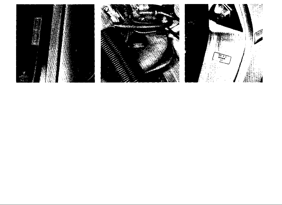
Location of Vehicle Identification
Number, Paint and Engine Number
When ordering spare parts or submitting
inquiries, always quote vehicle identification and engine number to assure correct
and prompt service.
Vehicle identification number Engine number Paint number
In accordance with Federal Safety Regulations, the vehicle identification number of your
car is located on the left windshield post and The engine number is stamped on the front The paint number is on the doorjamb on the
can be seen from the outside. reinforcing rib in the top half of the crankcase, driver's side.
6
Page 8
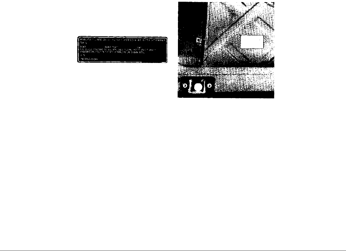
Safety Compliance Sticker
Vehicle Identification Label
The Safety Compliance Sticker is your assurance that your Porsche complies with all Federal Motor Vehicle Safety Standards which
were in effect at the time the vehicle was manufactured. It is located on the doorsill on the
driver's side.
The sticker also shows the month and year of
production and the vehicle identification number of your car (perforations) as well as the
Gross Vehicle Weight Rating and the Gross
Axle Weight Rating.
The vehicle identification label is located underneath the luggage compartment floor cover, next to the spare wheel well.
The label contains the following information:
1. Vehicle Identification Number
2. Vehicle Code
3. Engine and Transmission Code
4. Paint and Interior Code
5. Option Codes
A duplicate of the label is in your Warranty and
Maintenance brochure.
1
Page 9

Dear Porsche-Owner Before going on a trip...
A lot has gone into the manufacture of your
Porsche, including advanced engineering,
techniques, rigid quality control and demanding inspections. These engineering and safety
features will be enhanced by you...
the safe driver...
who knows his car and all controls,
who maintains his vehicle properly,
who uses his driving skills wisely.
You will find helpful hints in this manual on how
to perform most of the checks listed on these
pages. If in doubt, have these checks per-
formed by your Porsche dealer.
First things first
• Turn the engine off before you attempt any
checks or repairs on the vehicle.
• Be sure tires are inflated correctly. Check
for damage and tire wear.
• See that wheel bolts are properly tightened
and not loose or missing.
• Check engine oil level, add if necessary.
Make it a habit to have engine oil checked
with every fuel filling.
• Check coolant level to assure sufficient en-
gine cooling.
• Be sure you have a well charged battery.
• Check brake fluid level. If too low, have
brake system checked.
• Replenish windshield washer fluid.
• Check if engine hood is locked safely.
• Replace worn or cracked wiper blades.
• See that all windows are clear and unob-
structed.
• Keep air intake slots and area between engine hood and windshield free of snow and
ice, so that the heater and the windshield
wipers work properly.
• Check whether all light lenses are clean.
• Be sure all lights are working and headlights are aimed correctly.
• Check under vehicle for leaks.
• Be sure all luggage is stowed securely.
Emergency equipment
It is good practice to carry emergency equipment in your vehicle. Some of the things you
should have are: window scraper, snow brush,
container or bag of sand or salt, emergency
light, small shovel, first-aid kit, etc.
Page 10

In the drivers seat...
On the road...
• Check operation of horn.
• Position seat for easy reach of controls.
• Adjust inside and outside rear view mirrors.
• Use safety belts.
• Check operation of foot and parking brakes.
• Check all warning and indicator lights with
ignition on and engine stationary.
• Do not leave car idling unattended.
• Lock doors from inside, especially with
children in the car.
• To prevent inadvertent opening of doors
from inside or outside, drive with locked
doors.
• Always drive defensively. Expect the unexpected.
• Use signals to indicate turns and lane
changes.
• Turn on headlights at dusk.
• Always keep a safe distance from the vehicle in front of you, depending on traffic,
road and weather conditions.
• Reduce speed at night and during inclement weather.
• Observe speed limits and obey road signs.
• When tired, get well off the road, stop and
take a rest. Turn the engine off. Do not sit in
the vehicle with engine idling. See WARNINGS on "Engine Exhaust".
• When stopped or parked, always set the
parking brake. Move the selector lever to
"P" (Automatic transmission) or move the
gearshift lever to reverse or first gear (Manual transmission). On hills also turn the
wheels toward the curb.
• When stalled or stopped for repairs, move
the vehicle well off the road. Turn on emergency flasher and use other warning devices to alert other motorists. Do not park or
operate the vehicle in areas where the hot
exhaust system may come in contact with
dry grass, brush, fuel spill or other flammable material.
• Make it a habit to have the engine oil checked with every fuel filling.
9
Page 11
Do not invite car theft!
An unlocked car with the key in the
ignition switch invites car theft.
A steering wheel lock and a gong
alarm are standard equipment in your
Porsche. The gong will sound if you
open the driver's door while the key
is still in the ignition lock. It is your reminder to pull the key out of the ignition lock and lock the doors.
WARNING
Always remove the ignition key,
especially if children are left unat-
tended in the vehicle. Unsupervised
use of any vehicle key may cause
serious personal injury.
Do not leave your vehicle unattended with the key in the ignition
lock. Take the key and lock the
doors.
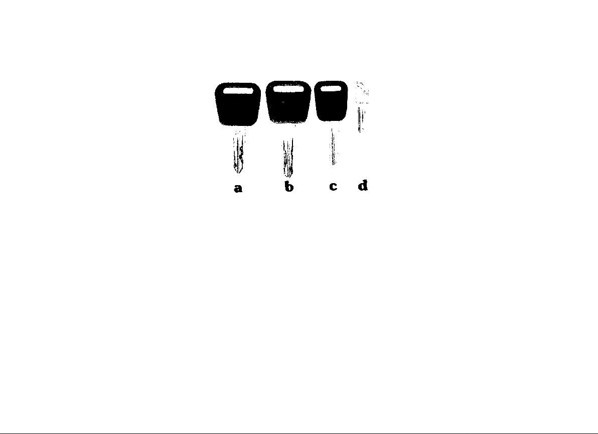
a Master key
b Auxiliary key
c Rear glove compartment key
d Key for lockable wheel nuts
Keys
Three keys are supplied with the vehicle. The
two master keys (black head) fit the ignition
lock, door locks, luggage compartment lock,
fuel filler cap lock and glove compartment lock.
The auxiliary key (read head) fits the ignition
lock, door locks, luggage compartment lock
and fuel filler cap lock.
WARNING
Do not remove the key from the steering
lock while you are driving or as the car is
rolling to a stop. The steering column is
locked when you remove the key, and you
will not be able to steer the car. This may
result in a serious accident.
Because of the symmetrical shape of the key
shaft, there is no "wrong" way of inserting the
key in the locks.
The new format of the master and auxiliary
keys makes unauthorized duplication of the
keys virtually impossible. This means, however, that you yourself will not be able to get
replacement keys cut, unless ordered from
the manufacturer.
For vehicles equipped with lockable wheel nuts,
four identical keys, four wheel nuts with lock
sleeve, plus a standard wheel nut for the spare
wheel, are included. When taking the vehicle
to your Porsche dealer or to a workshop for
wheel or tire service, remember to leave one
key with the service attendant.
In case of loss, duplicate keys cannot be
furnished by your Porsche dealer. Do not
leave these keys in the vehicle. Keep them
in a safe place.
See "Lockable wheel nuts" for details.
NOTE: It is a good idea to also keep a record of your key numbers in your wallet
together with your license.
10
Page 12
Key number
The key number of the ignition key is impressed on a plastic tag which comes with the
keys. Detach this tag and keep it in a safe place.
For your protection against theft:
• Record the key numbers and keep them in
a safe place, such as your wallet. Do not
keep them in the vehicle.
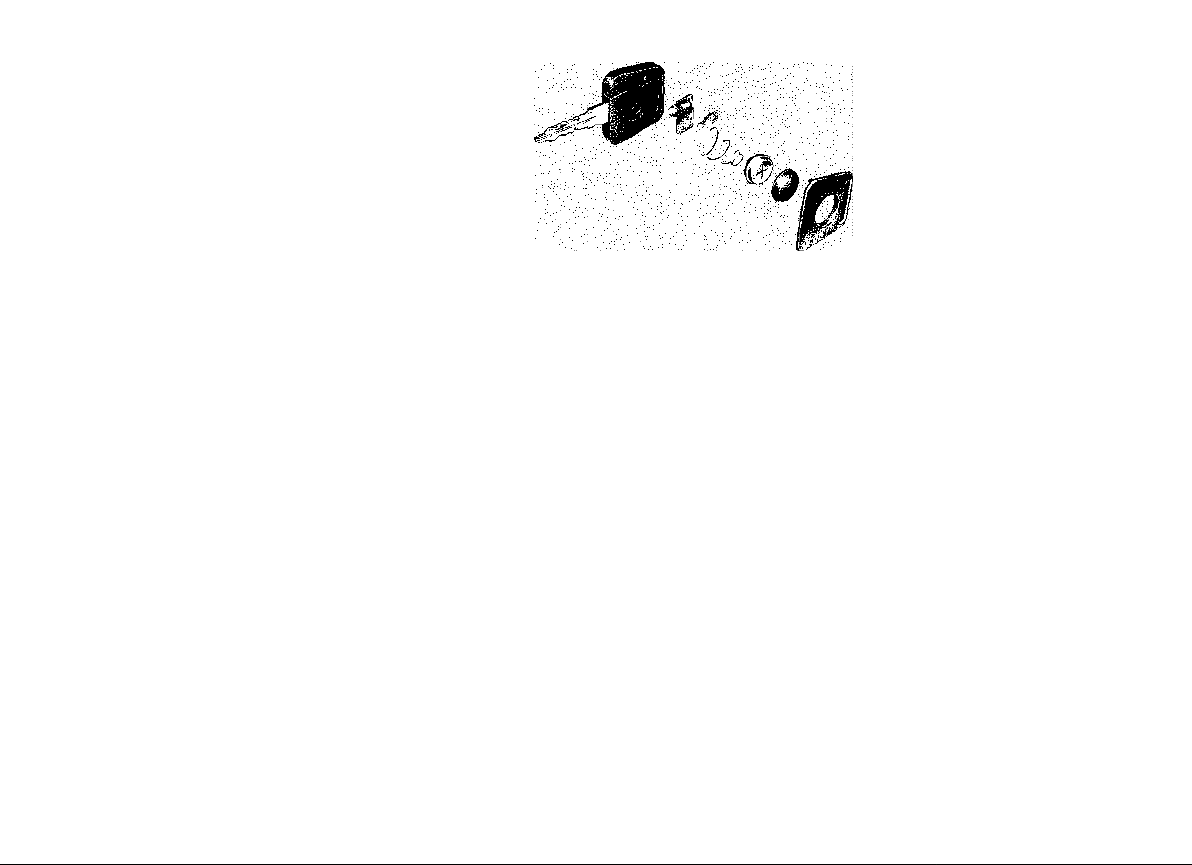
Key light
One master key has a built-in flashlight in the
key head. The beam from a small bulb in the
key head illuminates the lower part of the key
stem.
The flashlight is on as long as the contact button is depressed.
• If you should lose a key, provide your
Porsche dealer with the key number to obtain a duplicate key. Tell him whether you
need a master or an auxiliary key.
The flashlight is powered by a 1.5 Volt button
battery. When the beam begins to fade, replace the battery, because an old battery
may leak and damage your clothes.
Page 13
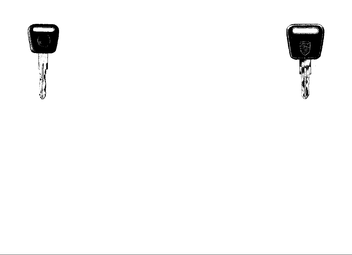
S-key
(illuminated)
Anti-theft alarm
Doors Activate alarm by locking with S-key.
Deactivate alarm by unlocking with S-key.
Auxiliary key - lock or unlock when alarm not required (see "Central
door locking system").
Luggage compartment Activate alarm by closing rear lid, then turn S-key counter-clockwise.
Ignition/steering
Glove compartment
Fuel filler cap
Deactivate alarm by unlocking rear lid with S-key.
Auxiliary key - lock or unlock when alarm not required.
Lockable with either key.
Lockable with S-key only.
Lockable with either key.
Auxiliary
key
If your Porsche is equipped with an anti-theft
alarm system, you will be given a duplicate
set of the master S-key illustrated above instead of the "regular" master key. The alarm
system can only be activated or deactivated
with the S-key.
Functions for both S-key and auxiliary key are
listed under "locking operations".
12
Attempting to open the doors, the rear lid or
the engine hood by any other means or turning
on the ignition when the alarm system is activated will produce an intermittent high noise
for about 30 seconds.
The engine cannot be started while the
alarm system is activated.
Keep the S-key in your personal possession
at all times. Leave the auxiliary key only with
an attendant when the car is being serviced.
Keep plastic tag with key number in a safe
place. Do not leave it in the vehicle.
Page 14
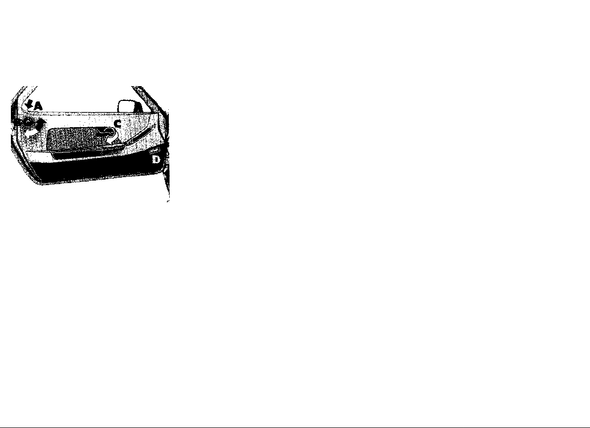
Doors
Central door locking system
The central door locking system enables you
to lock or unlock both doors simultaneously
by operating one door lock.
The central door locking system functions
only when both doors are fully closed. If one
door is "centrally" locked before the other
door is fully closed, the "centrally" locked door
will unlock automatically.
The car is safely locked when locking knob "A"
is fully down on both doors. If locking knob "A"
is not fully down on one door, open that door
again, close it firmly and repeat the locking
operation.
On a centrally locked vehicle, the passenger
door can also be unlocked and locked from
inside by turning locking knob "B". Locking
knob "B" is operational only with door fully
closed.
With the ignition key in Pos. "1" or "2" both
doors can be locked or unlocked by pressing
the central locking button in the center console. The button is illuminated when the doors
are locked.
With the ignition key in Pos. "0" the central
locking system is operational by turning knob
"B".
To open doors from outside, pull the recessed
door handle.
To open doors from inside, pull recessed
handle "C" above armrest.
The armrests have a built-in storage compartment. To open, press knob in hand cutout
and tilt armrest outward. To close, tilt compartment toward door panel.
The courtesy light in the lower door panel
"D" will come on when a door or the hatchback is opened. The light can also be turned
on or off with the switch on the light housing.
13
Page 15
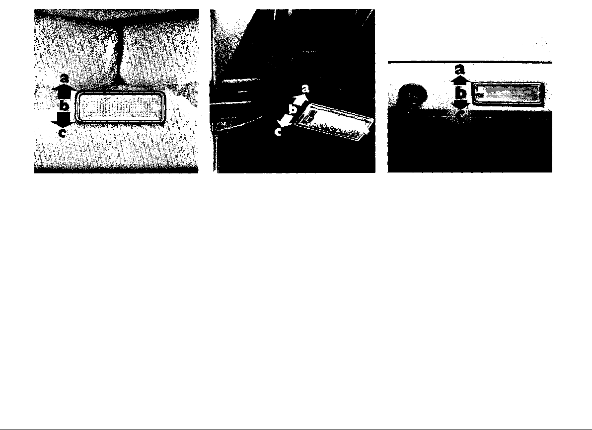
Interior lights
Dome lights
The dome lights have a built-in rocker switch
which is operated by tilting the lamp lens as
follows:
a light on continuously
b light off
c light on with front doors or hatchback open.
14
Door courtesy lights
Switch positions for the lower door panel lights
are as follows:
a light on with front doors or hatchback open
b light off
c light on continuously.
Luggage compartment light
The luggage compartment light is located on
the hatchback.The three switch positions are:
a light on with front doors or hatchback open
b light off
c light on continuously.
Page 16
Power windows
To open or close, depress the rocker switches
in the center console in front of the shift lever.
The power windows only work when the ignition is turned on.
Door warning lights
The red spot lights in the rear doorjambs will
come on when a door or the rear lid is opened.
WARNING
Do not put anything on or near the win-
dows that may interfere with the driver's
vision.
Remove the ignition key to shut off power
to the window switches when the vehicle
is not attended by a responsible person.
Page 17
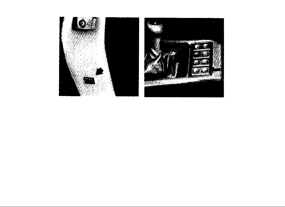
Front seats
The correct seating position is all-important
for safe and fatigue-free driving.
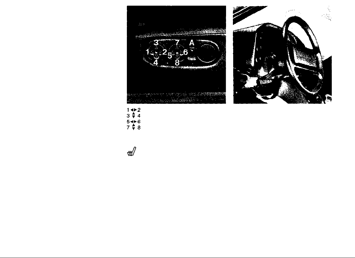
For individual adjustment of the desired seating position, two 4-position switches permit
infinitely variable electrical adjustment in a
longitudinal and vertical direction as well as
adjustment of the backrest inclination.
The rocker switches for the seat adjustment
are located at the outboard side of the seat.
We recommend the following procedure for
finding the correct position for the driver's seat:
1. Operate switch for longitudinal adjustment
until your leg is fully stretched with the clutch
pedal depressed while your foot is bent.
2. Adjust desired fore/aft height.
3. Clasp upper portion of steering wheel.Then
adjust backrest inclination so that both
shoulders remain in contact with the backrest even with your arms fully stretched.
4. If necessary, correct the longitudinal adjustment.
Longitudinal adjustment
Height adjustment, front
Backrest adjustment
Height adjustment, rear
Seat heating system
The seat heating system is turned on by means
of the key switch (A); it heats the seat pan and
backrest. After approximately 15 minutes, a
time relay shuts off the heating automatically.
You can also turn it off earlier by pushing the
key switch downward.
Steering wheel adjustment
For maximum legroom and unobstructed view
of the instruments, the height of the steering
wheel, together with the instrument cluster
unit, can be adjusted.
Release locking lever under instrument cluster
for desired positioning (arrow), then lock securely.
16
Page 18
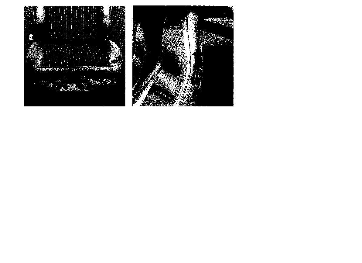
Manual operation
Should the electrical seat adjustment fail, you
can use the hexagon socket-screw in the toolkit for longitudinal seat adjustment by turning
the servo-motor at the front end of the seat.
Backrest release
The backrest can be folded forward for easy
access to the rear seats. To release, pull" the
lever on the side of the backrest up (arrow)
and, at the same time, tilt the backrest forward.
When the backrest is tilted back, the lock will
engage automatically.
WARNING
Front seat passengers should not ride in a
moving vehicle with the backrest reclined.
Safety belts only offer protection when the
backrest is upright and the belts are properly positioned on the body. Improperly
positioned safety belts can cause serious
personal injury in an accident.
Rear seats - luggage compartment
The backrests of the rear seats can be tilted
forward to provide additional luggage space.
Unsnap the luggage compartment cover from
the upright rear seat backrests and the rear
cross wall.
To release backrest, pull the lever on side of
the backrest up and, at the same time, tilt the
backrest forward.
17
Page 19
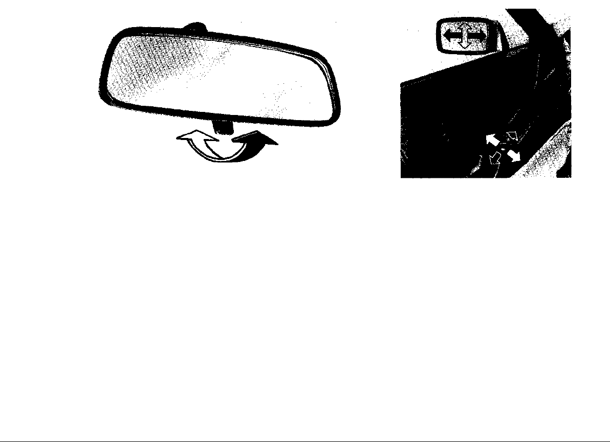
Rear view mirrors Inside day-night mirror Heated outside mirrors with remote control
You can adjust the day-night mirror from clear When the rear window defogger/defroster is
daylight visibility to non-glare visibility at night, switched on, the outside mirrors are also heatby moving the lever at the bottom of the mirror ed electrically. The outside mirrors can be adforward or rearward. justed from the inside by remote control when
the ignition is turned on. The control switch is
Adjust the outside and inside mirrors before driving off. It is important for safe driving that you have good vision to the rear.
18
Do not put decals or other signs on the win- located next to the side window vents in the
dows that may interfere with the driver's armrest.
vision.
Page 20

The electrically heated outside mirror for the
passenger side can be adjusted with the same
control switch, by pressing the rocker switch
beside the adjuster switch into the appropriate
position.
If necessary, the outside mirrors can also be
adjusted manually.
19
Page 21

Safety belts
WARNING
Failure to follow safety belt instructions
may result in serious personal injury.
INSTRUCTIONS
• For your and your passengers' protection, use safety belts at all times while
the vehicle is in motion.
• Safety belts must be properly positioned
on the body. Improperly positioned safety belts can cause serious personal injury in case of an accident. Therefore,
heed all of the following warnings and
instructions.
• A combination lap-shoulder belt should
not be worn by a person less than 4' 11"
or 1.5 m in height, because it would not
be in its most protective position and,
therefore, may increase the possibility
of injury in an accident.
• Persons smaller than 4' 11" or 1.5 m in
height and children who are able to sit
upright by themselves should use one
of the rear seating positions and the lap
belt provided.
• For maximum safety and protection, we
recommend that small children travel in
the rear seats.
• When driving in foreign countries, remember that some require the wearing
of safety belts by law.
• Do not strap in more than one person
with each belt.
• For maximum effectiveness, the lap belt
should be worn low across the pelvic
crest.
• Do not wear shoulder part of belt under
your arm or otherwise out of position.
This would increase the possibility of
serious injury in case of an accident.
• Belts should not be worn twisted.
• Do not wear belts over rigid or breakable
objects in or on your clothing, such as
eye glasses, pens, keys, etc. as these
may cause injury.
• Several layers of heavy clothing may in-
terfere with proper positioning of belts.
• Belts must not rub against sharp objects.
• Keep belt buckles free of any obstruction that may prevent secure locking.
• Make sure that belt of the unoccupied
passenger seat is fully wound up on its
retractor so that the belt tongue is in its
stowed position. This reduces the posibility of the tongue becoming a striking
object in case of a sudden stop.
• Belts that have been subjected to excessive stretch forces in an accident
must be replaced.
• If belts show damage to webbing, bindings, buckles or retractors, they should
be replaced.
• If belts do not work properly, see your
authorized Porsche dealer.
• Do not modify or disassemble the safety
belts in your vehicle.
• The belts must be kept clean as otherwise the retractors may not work properly (see also "Car care instructions").
• Never bleach or dye safety belts.
• Do not allow safety belts to retract until
they are completely dry.
20
Page 22
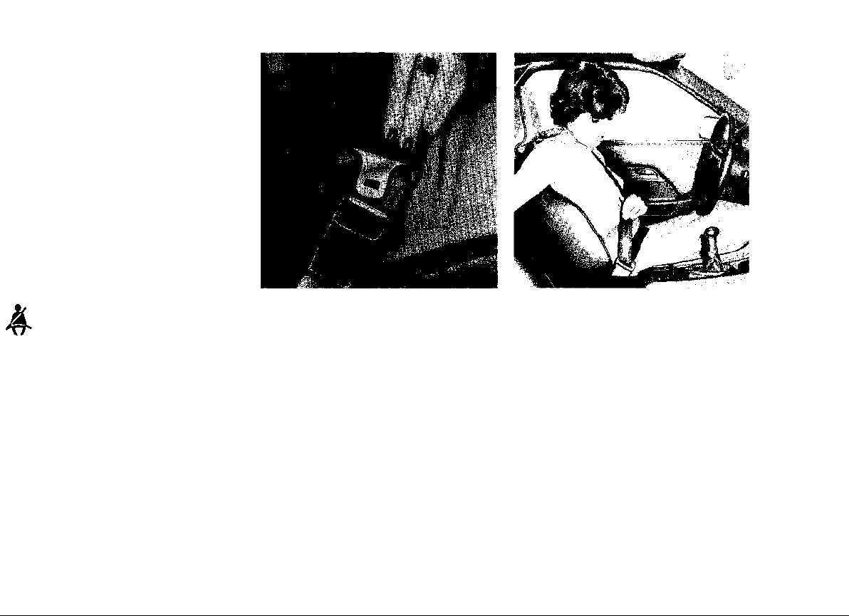
Safety belt warning system Inertia reel retractor
The combination lap/shoulder belt with inertia
reel locking mechanism adjusts automatically
to your size and movements as long as the pull
on the belt is slow.
An audio-visuel warning system is interconnected with the driver's safety belt.
Every time the ignition is turned on, the seat
belts warning light in the center console will
come on for about 6 seconds as a reminder to
buckle up. If the driver does not fasten the
safety belt, the gong will also come on. The
gong will go off as soon as the driver has
buckled up.
Rapid deceleration during hard braking or a
collision locks the belt. The belt will also lock
when you drive up or down a steep hill or in a
sharp curve.
• To fasten, grasp latch and pull belt in continuous slow motion across your chest and lap.
• Insert latch into buckle on inboard side of
seat. Push down until it is securely locked
with an audible click. Pull belt to check.
• Pull shoulder section to make sure belt fits
snugly across the hips.
• Belts should fit snugly across the pelvis and
chest. Make sure any slack is wound on the
retractor.
21
Page 23

• To unfasten belt, push in release button on
buckle. Belt will spring out of buckle.
• To release a locked belt, lean back to take
the body pressure off the belt.
• To store lap/shoulder belt, allow belt to wind
up on retractor as you guide latch to its
stowed position on doorpost.
22
Lap belts for rear seats
The belt with inertia reel locking mechanism
adjusts automatically to your size and movements as long as the pull on the belt is slow.
Rapid deceleration during hard braking or a
collision locks the belt. The belt will also lock
when you drive up or down a steep hill or in a
sharp curve.
• To fasten lap belt, grasp latch on outboard
side of seat and slowly pull across the pelvis. insert latch into buckle on inboard side
of seat and push down until it is securely
locked with an audible click. Pull belt to
check. To unfasten belt, push in release
button on the buckle.
• To store belt, allow belt to wind up as you
guide latch to retractor.
Page 24
To set the parking brake
Loudspeaker balance control
Parking brake lever (arrows)
Parking brake force is mechanically trans-
ferred to the rear wheels by means of cables.
Use the parking brake only after the vehicle has come to a full stop.
Press in the release button (arrow) at the end
of the lever as you pull the lever up. The parking brake engages as soon as you release the
button in the raised lever.
To release the parking brake
Pull the lever slightly up as you depress the
release button. Keep the button depressed
as you lower the lever.
WARNING
• Release the parking brake fully. A partially engaged brake will overheat the
rear brakes, reduce their effectiveness
and cause excessive wear.
• Always set the parking brake when parking your car. Move the selector lever to
"P" (Automatic transmission) or move
the gearshift lever to reverse or first gear
(Manual transmission). On hills also turn
the wheels toward the curb.
The central warning light and the parking brake
light will go out after the engine is started and
the parking brake is fully released (see "Central warning light system").
The volume of the loudspeakers in the door
and in the rear of the vehicle can be balanced
by turning the loudspeaker balance control
knob (A), located next to the parking brake
lever.
Hatchback release
With one or both doors open, you can release
the hatchback by pulling either button "B" on
the left of the driver's seat or the respective
button on the right of the passenger's seat.
The hatchback will open automatically.
Also see "Hatchback".
23
Page 25

Brakes
Brake pedal
Brake operation and brake warning light
Functioning of brake system
Your Porsche is equipped with a power assisted hydraulic dual circuit brake system with
disc brakes at the front and at the rear. Both
circuits function independently.
In the unlikely event of hydraulic failure of
one circuit, push the brake pedal down
firmly and hold it in that position. A mechanical linkage activates the second circuit,
and you will be able to bring the vehicle to
a safe stop.
WARNING
Failure of one brake circuit will impair the
braking capability resulting in an increased
stopping distance.
If one brake circuit has failed, the other will still
operate. However, you will notice an increased
pedal travel when you step on the brake.
Should you encounter such experience, bring
your vehicle safely to a full stop.
Avoid driving the vehicle and have it towed
to the nearest authorized Porsche dealer.
WARNING
• The movement of the brake pedal must
never be obstructed by a floor mat or
any other object. In case one of the two
brake circuits fails, increased pedal tra-
vel is required to bring your vehicle to a
full stop.
• Make sure that the size of your floor mat
does not hamper the movements of
either brake, clutch or accelerator pedals in any way.
• Secure the floor mat against sliding into
positions that could interfere with the
safe operation of your vehicle.
• Do not "ride the brakes" by resting your
foot on the pedal when not intending to
brake. Overheating and wear of the
brakes is the result.
• Before descending a steep grade, reduce speed and shift transmission into
a lower gear or driving position to control speed. Do not ride the brakes or hold
pedal down too long or too often. This
could cause the brakes to get hot and
not function properly.
Make it a habit to check the operation of your
brakes before driving.
The central warning light and the brake fluid
warning light in the combination instrument
will flash when the level in the brake fluid reservoir is too low (see "Central warning light
system").
With correctly adjusted brakes, and a correct-
ly working brake system, the pedal travel to
the point of brake actuation should be 1 -3/16"
to 1 -9/16" or 30 to 40 mm. Whenever the brake
pedal travel exceeds this distance, have the
brake system checked.
Keep in mind that the braking distance increases very rapidly as the speed increases.
At 60 mph or 100 km/h, for example, it is not
twice but four times longer than at 30 mph or
50 km/h. Tire traction is also less effective
when the roads are wet or slippery. Therefore,
always maintain a safe distance from the car
in front of you.
24
Page 26

Brake booster
New brake pads or linings
Clutch
The brake booster assists braking only
when the engine is running.
When the car is moving while the engine is not
running, or if the brake booster is defective,
more pressure on the brake pedal is required
to bring the car to a halt.
Moisture or road salt on brakes affects
braking
WARNING
Driving through water may reduce the trac-
tion. Moisture on brakes from road water
or car wash or coating of road salt may affect braking efficiency. Cautiously apply
brakes for a test. When the vehicle is driven
on salted roads for extended periods, the
brakes should be hosed down thoroughly
about every 2 weeks. An automatic carwash facility cannot do this job properly.
Brakes will dry after a few cautious brake
applications.
Brake wear
Our automobiles have excellent brakes, but
they are still subject to wear, depending on
how the brakes are used. Have the brake system inspected at the intervals recommended
in your Warranty & Maintenance booklet.
Brake pads or linings may not have the highest
possible braking efficiency when new. Therefore, allow for longer braking distance during
the initial 100 to 150 miles or 150 to 250 kilo-
meters of normal city driving if fewer stops are
realized.
Due to the hydraulic operation of the clutch, a
free travel of the clutch pedal of 0,1" or 2.5 mm
is necessary.
Should this free travel suddenly become bigger, it could mean a malfunction of the clutch.
See your Porsche dealer for rectification.
Always depress the clutch pedal fully when
changing gears. Do not hold the car on a steep
hill with the clutch pedal partially depressed.
This may cause premature wear or damage.
Page 27
Ignition/Starter Switch with
Steering Lock
The steering is equipped with an anti-theft
ignition lock.
There are 4 switch positions:
0 Steering locked. All electric circuits wired
through the ignition switch are turned off.
The ignition key can only be withdrawn in
the "0" position. The parking lights can be
operated in this position by pushing the turn
signal indicator lever up and down (also see
"Parking lights").
1 Steering unlocked. In this position all elec-
tric circuits are operational except for the
following: turn signals, back-up lights, outside mirror remote control, rear window defogger/defroster and fresh air ventilation.
2 Ignition on, steering unlocked. All electric
circuits are operational. With the engine
stationary, the central warning light and all
individual warning lights located in both
combination instruments will light up for a
bulb check. If the engine oil level is too low
the central warning light will flash. (Lack of
engine oil can only be checked with the
dipstick, with the engine turned off and with
the vehicle on level ground.)
3 The starter is operated by turning the ig-
nition key to the right. As soon as the engine
starts, release the key. It will spring back to
position "2". With the engine running, the
central and individual warning lights should
go out. The STOP LAMP will go out after
depressing the brake pedal and the PARK
BRAKE light after fully releasing the parking
brake (see "Central warning light system").
To conserve battery power, the electric circuits for headlights, rear window defogger/
defroster and wiper/washer system are
temporarily interrupted during the starting
process.
The starter should not be operated for more
than 10 to 15 seconds at a time. If the engine
does not start the first time or stalls at any time,
the ignition key must be returned to the "0"
position. The non-repeat lock in the switch
prevents the starter from being operated when
the engine is running and thus from being
damaged.
To remove the key and to lock the steering,
turn the key back to position "0" and pull it out.
Turn the steering wheel until it locks.
WARNING
Never remove key from ignition lock or turn
key off while vehicle is moving. The steering
wheel will lock, causing loss of control.
Gong
If you leave the key in the ignition/steering
lock, the gong will sound when the driver's door
is opened. This is your reminder to remove the
key.
For further details see "Starting Procedures"
on the following page.
26
Page 28
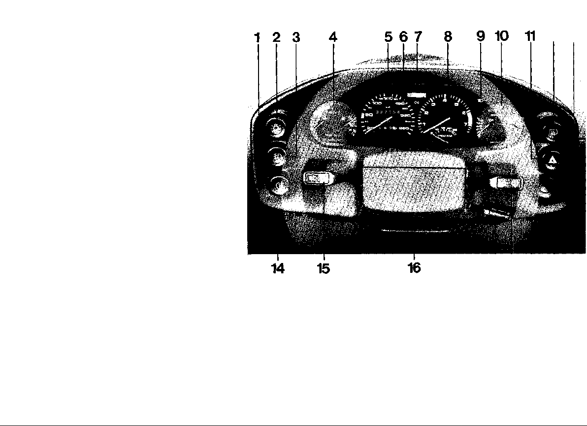
Instrument cluster
12 13
17 18 19 20
1 Odometer reset switch
2 Light switch
3 Fog light switch
4 Left combination instrument
5 Speedometer
6 Turn signal indicator light
7 Central warning light
8 Tachometer
High beam indicator light
9
10 Right combination instrument
10
Emergency flasher switch
11
Rear window defogger switch
12
Ignition/starter switch with steering lock
13
Instrument illumination control
14
15 Turn signal/headlight dimmer flasher/
15
parking light switch lever
16 Locking lever for steering wheel/
instrument cluster height adjustment
17 Automatic speed control lever
18 Windshield wiper and windshield/head-
light washer switch lever
19 Intensive washer system switch
20 Intermittent wiper interval control
Page 29

Page 30

Starting Procedures
WARNING
• Fasten safety belts before driving off.
• Never start or let the engine run in an enclosed, unventilated area. Exhaust fumes
from the engine contain carbon monoxide, which is a colorless and odorless gas. Carbon monoxide can be fatal
if inhaled.
• Never leave engine idling unattended.
An unattended vehicle with a running
engine is potentially hazardous.
• Do not park or operate the vehicle in
areas where the hot exhaust system may
come in contact with dry grass, brush,
fuel spill or other flammable material.
• Never leave engine idling. When starting
engine, be ready to drive off immediately. Maintain moderate speed until engine
is warm.
Temperature sensors on the engine automat-
ically provide the correct fuel/air mixture re-
quired for starting.
Therefore, it is not necessary to depress the
accelerator pedal while starting a cold or a
warm engine.
When starting at very low outside temper-
atures, fully depress the clutch pedal, so that
the starter only has to crank the engine.
As soon as the engine starts, release the ig-
nition key.
If the engine fails to start after 10 to 15 seconds of cranking, wait about 10 seconds
before restarting.
Do not let the engine idle to warm it up. After
starting, accelerate gradually and maintain
moderate speed. Avoid high rpm and full throt-
tle until the engine has reached normal oper-
ating temperature.
Stopping engine
Turn key back to position 0.
WARNING
• Before you check anything in the engine
compartment, let the engine cool down.
Hot components can burn skin on contact.
• The radiator fan switches on automatically when the coolant reaches a certain
temperature and continues to run (even
with ignition off) until the coolant temperature drops. Therefore, never touch
the fan blades as they will rotate spontaneously when the thermoswitch turns
the fan on.
If your have an automatic garage door...
The transistorized ignition system in your
Porsche may interfere with your electronically
operated garage door. To check this: drive
your Porsche close to the garage door and run
the engine at different speeds.
Manual transmission:
Move gearshift lever to Neutral.
Automatic transmission:
Move gearshift lever to Neutral or Park.
Do not stop engine immediately after hard
or extended driving. Keep engine running
at increased idle for about two minutes to
prevent excessive heat build-up before
turning off engine.
If the garage door opens or closes without
your operating the garage door unit in your car,
contact the dealer who installed the automatic
garage door to have the frequency and/or
coding of the garage door signal modified.
27
Page 31

Light switch -with ignition on
Fog lights
0 lights off
1 parking lights on (2 front/2 rear)
2 headlights on and raised
In positions 1 and 2, the following lights are
also on:
tail lights
instrument illumination
shift pattern illumination for automatic transmission selector lever
28
When you open the door while the lights are
on, the gong will sound. It is your reminder to
switch off the lights.
Instrument illumination control
With headlights on, the brightness of the instrument illumination can be adjusted by turning the thumbwheel on the left side underneath
the instrument cluster.
With headlights on, the fog lights can be turned
on or off by depressing switch "A". The switch
is illuminated when the fog lights are on.
Trip odometer
The trip odometer in the lower part of the
speedometer can be turned back to zero by
depressing switch "B".
Page 32

Manual transmissions
Tachometer
The transistorized tachometer operates on
the pulse count principle and shows engine
speed in revolutions per minute (rpm).
The red mark at the end of the scale indicates
the maximum permissible engine rpm. Before
reaching this area, the next higher gear should
be selected. Earlier shifting saves fuel.
Shift to the next lower gear when the engine
rpm drops below 1500 rpm.
Automatic transmissions
Indicator system for position
of gearshift
Whenever the ignition is switched on, or the
vehicle lights are switched on, the position of
the gearshift lever lights up in the display field
of the tachometer.
The display goes off when the key is removed
or when the vehicle lights are switched off.
Computer Assisted Shift Indicator System
(Manual Transmission only)
A computer continually evaluates vehicle data,
such as driving speed, engine rpm, engine
load and engine temperature.
When the CASIS arrow in the tachometer
lights up, it means the engine could operate
more economically. The light indicates that
you can increase fuel efficiency by shifting into a higher gear. The CASIS light will go out
when a higher gear has been engaged, when
taking your foot off the gas pedal or when accelerating at a higher rate. In fifth gear the
CASIS light is inoperative.
During maximum acceleration, the CASIS ar-
row light will only light up at a point where engine rpm is such that improved acceleration
can be obtained by shifting into the next higher
gear. This means the CASIS arrow does not
indicate any set shift point, but that the com-
puter calculated shift points depend on the
way you drive. The arrow will light up at the
lowest speed range when cruising, and the
highest speed range when accelerating with
wide open throttle.
29
Page 33

How to use CASIS
|Q) High beam indicator light
Drive your Porsche shifting as you normally
would.
As soon as the engine reaches uneconomical
load range, the CASIS light will remind you to
shift into the next higher gear to keep the engine at the same performance level but with
lower fuel consumption.
You will get used to CASIS quickly and as a
result operate your Porsche with the CASIS
arrow light coming on only now and then.
WARNING
Use CASIS to your best advantage but remember that traffic, road and weather conditions must always have priority when
shifting gears or changing speeds.
Speedometer
The speedometer indicates driving speed per
hour.
In USA: miles and kilometers per hour
In Canada: kilometers per hour
The upper odometer records total distance
driven and cannot be turned back.
The trip odometer in the lower part of the instrument can be turned back to zero by de-
pressing the odometer reset switch on the
lower left side of the instrument cluster.
The blue light in the instrument cluster will light
aup when the switch lever is pushed forward.
The blue light will go out when switching to low
beam.
Turn signal indicator light
The green indicator light in the instrument
cluster will flash with the switch lever in either
up or down position. If a turn signal bulb becomes defective, the indicator light flashes at
about twice the normally frequency.
Central warning light
The central warning light in the instrument
cluster will light up or flash when a fault occurs
in one of the vehicle's systems. (Refer to "Central warning system").
30
Page 34

Coolant temperature gauge
and warning light
Needle in lower field - engine is cold
As long as needle is in lower field, avoid
high speeds and high engine rpm, until engine has reached normal operating temperature. Do not lug the engine.
Needle in center field - normal
Under normal driving conditions, needle should
remain in center field. The needle may reach
the upper field, especially at high engine loads,
but should return to "normal" when engine
load is reduced.
Needle in upper field - warning
If needle enters the upper field, the engine is
overheating. The central warning light will also
come on. Reduce speed and engine rpm. If
the needle does not return to the center field,
and the central warning light remains on, pull
off the road, turn off the engine and let it cool
down.
Coolant temperature warning light
If this light comes on, check whether the V-belt
driven mechanical fan is working. If the fan is
not working, the V-belt may be loose or broken.
The belt should be tensioned or replaced.
Do not continue to drive with a broken
V-belt.
On vehicles equipped with a factory installed
air conditioner, also check whether the electric
fan in front of the air conditioner is working.
WARNING
• Before you check anything in the engine
compartment, let the engine cool down.
Hot components can burn skin on con-
tact.
• The air conditioner condenser fan is
electrically driven. It is switched on automatically by a thermostat when the
coolant reaches 92° C/198" F. Even when
the engine is turned off, the fan will continue running, until the coolant temperature has dropped to 87° C/189 F and
until the engine itself has cooled down
sufficiently. Therefore, never touch the
fan blades as they will rotate spontaneously when the thermoswitch turns the
fan on.
• Be careful if you have to remove the cap
from a hot coolant fluid reservoir (expansion tank). Protect your hands, arms
and face against scalding. Use a thick
rag and open the cap carefully one turn
to allow excess pressure to escape before removing the cap.
If the electric fan is not working, there may be
a malfunction in the temperature sensor switch
or in the electrical system. Check for a blown
fuse.
If the problem cannot be readily located, be
sure the engine has cooled down sufficiently.
Then drive to the nearest Porsche dealer, but
carefully watch the coolant temperature gauge
and the warning light. Try to avoid engine idling, very low speeds and engine speeds in
excess of 4000 rpm.
For other details refer to "Cooling System".
31
Page 35

Fuel level gauge and
warning light
With the ignition on, the amount of fuel in the
tank is indicated by the fuel gauge needle.
Warning lights
(see "Central warning light system")
BELT TEN.
The warning light indicates insufficient tension
of the toothed belt. Have the toothed belt
checked and re-tensioned at the nearest workshop.
TAIL LAMP
The warning light comes on when a bulb is
defective.
STOP LAMP
The warning light comes on and goes out after
depressing the brake pedal. If the light stays
on a bulb is defective.
Trailer turn signal indicator light
Not connected
COOLANT
The warning light comes on when the fluid
level in the expansion tank falls below the required minimum. Occasionally, the light may
come on when starting the engine. As soon
as the engine warms up, the coolant in the reservoir will expand, rise above the minimum
level, and the light will go out. If the COOLANT
warning light remains on, top up immediately
and have the cooling system inspected for
leaks.
For other details refer to "Cooling System".
Fuel level warning light
This light comes on when the fuel reserve level in the tank is down to about 2 U.S. gals,
or 8 liters. Time to refuel.
The central warning light and the warning lights
in the combination instrument light up for a
bulb check when the ignition is turned on. They
should go out as soon as the engine is started.
Also see "Central warning light system".
32
WASH FLUID
The warning light comes on when level in the
windshield/headlight washer reservoir is down
to 2 U.S. qts. or 2 liters.
PARKING LIGHTS
The indicator comes on when the parking lights
are turned on. The light will go out as soon as
the headlights are switched on.
Page 36

Voltmeter
Alternator warning light
Warning Lights
(see "Central warning light system")
BRAKE FLUID
Oil pressure gauge
Oil pressure warning light
Engine oil pressure is shown in bar. At 5000
rpm, with the engine at normal operating temperature, the oil pressure should be about 5
bar. A slight drop in oil pressure at higher temperatures is normal.
If the oil pressure should drop suddenly while
you are driving, this light and the central warning light will flash. Pull off the road and stop
the engine immediately. Check the engine
oil level. If it appears to be normal, contact the
nearest workshop.
The voltmeter shows the overall condition of
the charging system. The needle should normally stay in the 12-14 volt range when the
engine is running. A temporary drop below 12
volts when starting the engine is normal.
The alternator warning light comes on when
the ignition is turned on and goes out as the
engine rpm increases. If the light does not light
up when turning the ignition on, or if it does not
go out after starting the engine, there may be
a malfunction in the electrical system. If this is
the case, contact your Porsche dealer. If the
light flickers or stays on while you are driving,
the V-belt may be loose or broken. The belt
should be retensioned or replaced. The fault
may also be in the regulator or the alternator
itself. In this case, keep electrical consumption
at a minimum and drive to the nearest workshop.
The central warning light and the warning
lights in the combination instrument light up
for a bulb check when the ignition is turned on.
They should go out as soon as the engine is
started. Also see "Central warning light sys-
tem".
The warning light flashes when the brake fluid
level falls below the required minimum.
BRAKE PAD
The warning light comes on when a brake pad
is worn.
PARK BRAKE
The warning light comes on and stays on until
parking brake is fully released.
ENGINE OIL
The warning light flashes if, with the ignition
on, the engine stationary, and the vehicle on
level ground, the amount of oil in the sumps is
less than 1.59 U.S. gal. or 6 liters.
Do not attempt to start the engine! Add oil
at once.
33
Page 37

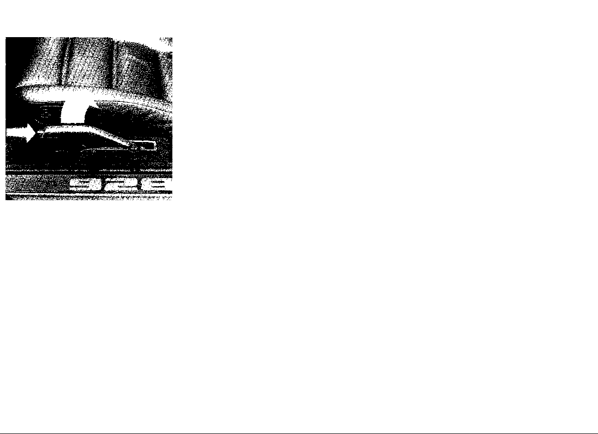
Rear window defogger/
defroster
The rear window defogger/defroster heating
element is actuated by a push button/rotary
switch. The switch is illuminated when the
heating element is energized.
After the rear window has been cleared, switch
off the rear window defogger to avoid unnecessary drain on the battery.
To defog - switch not depressed
Emergency flasher switch
If your car is disabled or parked under emergency conditions, depress the switch to make
all four turn signals flash simultaneously. The
light in the switch flashes at the same frequency.
The emergency flasher works independ-
ently of the ignition switch position.
34
WARNING
• Whenever stalled or stopped for repair,
move the car well off the road. Turn
on the emergency flasher and mark the
car with road flares or other warning
devices. Do not remain in the car.
• Do not park or operate the car where the
hot exhaust system may come in con-
tact with dry grass, brush, fuel spill or
other flammable material.
• Before working on any part in the engine
compartment, turn the engine off and let
it cool down sufficiently. Hot compo-
nents can burn skin on contact.
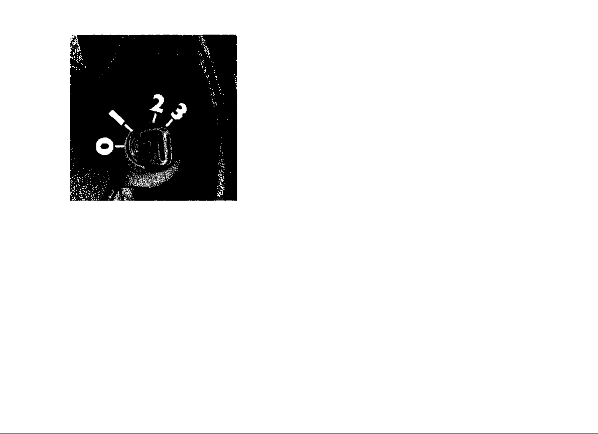
0 Heating element off.
1 Heating element on. The heating element
will provide a steady energy output to keep
the rear window free from fog.
To defrost - switch depressed (arrow)
0 Heating element is fully energized for de-
frosting. After about 15 minutes the heating
turns off automatically.
1 Heating element is fully energized for de-
frosting. After about 15 minutes, the heating element automatically reduces energy
output to "defogging".
Page 38

Switch lever for Turn Signal/
Headlight Dimmer with ignition on
and Parking Lights with ignition
off
Turn signal indicator
Lever up - right turn signal (arrow 3)
Lever down - left turn signal (arrow 4)
The turn signal lever turns off automatically
when the steering wheel is straightened out
after completing a turn.
If a turn signal bulb becomes defective,
the indicator light flashes at about twice
the normal frequency.
Lane changer
To indicate your intention when changing lanes
on expressways, slightly lift or depress the
turn signal indicator lever to the resistance
point. The lever turns off automatically when
released.
High beam/low beam headlight dimmer with light switch in position 2, push lever forward to select high beam (arrow 1). The blue
indicator light in the instrument cluster comes
on when high beam is switched on.
Pull lever toward steering wheel (arrow 2) to
select low beam.
You can flash signal other motorists by repeatedly pulling and releasing the lever.
Headlight flasher
During daylight, you can flash signal other
motorists with your foglights (in lieu of horn)
by repeatedly pulling and releasing the lever.
Parking lights
Lever up right side parking lights on (arrow 3)
Lever down left side parking lights on (arrow 4)
35
Page 39

1 Set/accelerate 2 Reset 3 Cancel
Automatic Speed Control
The automatic speed control allows you to
maintain a constant cruising speed of 30 mph
(50 km/h) or higher, without actuating the accelerator pedal. Any manual operation, such
as accelerating, gearshifting or braking can
be done independent of the automatic speed
control. The spring loaded control lever operating the automatic speed control is located
just below the wiper/washer lever.
While driving with the automatic speed
control set (at speeds above 30 mph or
50 km/h), do not bring shift lever into the
Neutral position to prevent excessive engine rpm.
To operate the automatic speed control
Accelerate to the desired cruising speed, push
lever toward instrument cluster (arrow 1) and
release. This sets the cruising speed and stores
it in a memory.
After a second or two, automatic speed control
will take over, and you can remove your foot
from the accelerator pedal. The set cruising
speed will be maintained automatically.
WARNING
Do not use the cruise control when it may
be unsafe to keep the car at a constant
speed. For example, a constant speed may
not be safe in heavy traffic, or on winding
or slippery roads. With the cruise control
system engaged, the engine speed will not
return to idle when removing the foot from
the accelerator pedal.
Please observe all local and national speed
limits.
Passing: When you want to drive faster for a
brief moment, for example when passing another vehicle, actuate the accelerator. When
you take your foot off the accelerator pedal, the
preset speed will automatically be resumed.
Gearshifting: When shifting gears, the automatic speed control is only disengaged as long
as the clutch pedal is depressed. The preset
speed will be resumed as soon as you take
your foot off the clutch pedal.
Braking and stopping: Whenever you apply
the brake or come to a stop, the automatic
speed control is disengaged. Move the lever
down (arrow 2), and the preset speed will be
resumed.
Switching system off: To switch the automatic speed control off, move the lever toward
you (arrow 3). To resume the preset speed,
move the lever down (arrow 2).
To change the preset cruising speed
Increase preset speed:
Accelerate by depressing the accelerator pedal. When the desired speed is reached push
lever toward instrument cluster (arrow 1) and
take the foot off the accelerator pedal. Now
the new cruising speed is set and stored in the
memory.
As an alternative, you can hold the lever in the
front position (arrow 1), without depressing the
accelerator pedal. The car will accelerate on
its own. When the desired speed is reached,
release the lever.
Decrease preset speed:
Apply the brake, which will disengage the automatic speed control. When the vehicle has
slowed down to the desired speed, push lever
toward instrument cluster (arrow 1) to set the
new cruising speed.
As an alternative, disengage the automatic
speed control by moving the lever toward you
(arrow 3). When the vehicle has slowed down
to the desired speed, push lever toward instrument cluster (arrow 1) to register the new
cruising speed in the memory.
Note: When driving up a hill, if the engine power is insufficient in a particular gear, the speed
control will be disengaged automatically. Shift
to a lower gear to avoid lugging the engine.
36
Page 40

Switch lever for windshield wiper/
washer and headlight washer
This lever has 6 switch positions. The electric
wiper system Is actuated by pulling the lever
up or down to the following 4 positions:
0 wipers turned off
1 wipers on slow speed
2 wipers on medium speed
3 wipers on fast speed
4 wipers on intermittent speed
The intermittent wiper interval can be adjusted
by turning thumbwheel "A" on the right side
underneath the instrument cluster.
The electric washer system is actuated as follows:
5 Pull lever toward steering wheel to operate
windshield washer. Fluid can be sprayed
into the windshield from any selected wiper
speed position. When the ignition is switched
on, the washer nozzles are heated, depending on the outdoor temperature.
6 Push lever toward instrument cluster to
operate headlight washer.
The headlight washer system operates only
with the headlights on and raised.
Avoid running the wiper blades over a dry
windshield to prevent scratching the glass.
Spray on washer fluid first. A scratched
windshield will reduce visibility.
Always loosen blades frozen to glass before operating wipers to prevent damage
to wiper motor.
WARNING
Worn or dirty wiper blades will reduce visi-
bility, making driving hazardous. Clean
blades regularly to remove road film and
carwash wax buildup. Use an alcohol base
cleaning solution, a lint free cloth and wipe
lengthwise.
Clean all inside and outside window glass
regularly. Use an alcohol base cleaning
solution and wipe dry with a lint free or a
chamois cloth.
(seen from below)
Intensive windshield washer
system (where applicable)
By depressing switch "B" on the right side underneath the instrument cluster, a supply of
special intensive cleaning solution is pumped
to the windshield. Heavy road dirt, silicone or
insects can be removed quickly without smearing. The spray duration is controlled by a time
relay to avoid excessive use of the special
cleaner. The regular windshield wiper/washer
system can then be operated to finish the
cleaning process.
37
Page 41

The control function of the central warning light
system is divided into two major groups:
Central warning light system
This electronic warning system monitors the
most important functions of your Porsche for
increased safety and reliability of performance.
Should a problem arise, the central warning
system will inform you immediately.
The central warning light is located in the top
center of the instrument cluster. The indivi-
dual warning lights are divided between the
two combination instruments.
When the ignition is turned on, the central
warning light and all individual warning lights
will light up for a bulb check. If the engine oil
level is too low the central warning light will
flash. (Lack of engine oil can, in comparison
with all other functions, only be checked with
the engine turned off, and with the vehicle on
level ground.) As soon as the engine is started,
the lights should go out. The STOP LAMP light
will go out after the brake pedal has been depressed. The PARK BRAKE light will go out
as soon as the parking brake lever is fully
released.
Should a problem arise, the central warning
light will light up or flash, together with the respective individual warning light.
Group "A" - engine oil pressure
- engine oil level
- brake circuit (pressure) failure
- brake fluid level
Any of these malfunctions reported by the
system must be corrected immediately.
Group "B" - brake wear (pads) indicator
- parking brake
- coolant level
- coolant temperature
- fuel reserve level
- windshield and headlight
washer fluid level
- stop lamps
- tail lamps
- toothed belt tensioning
Any group "B" malfunction reported by the
system should be corrected as soon as possible.
38
Page 42

10 11
12
13 1415 16 17
Dashboard panel
and center console
1 Side window defogger/defroster vents
2 Instrument cluster
3 Automatic climate control
4 Reset button for central warning light
5 Center air vents
6 Safety belt warning light
7 Central door locking button
8 Glove compartment lock
9 Open storage shelf
10 Side view mirror adjuster
11 Front-hood release lever
12 Horn
13 Power window switches
14 Electric sliding roof switch
15 Rear window wiper switch
16 Gearshift lever
17 Clock
Page 43

Reset button (white arrow)
By pressing this button, you can turn off the
central warning light for group "B" related
problems. The individual warning light in the
respective combination instrument will remain
on as a reminder to have the fault corrected.
The reset button does not apply to group
"A" related problems. Both central and indi-
vidual warning lights will continue to flash because an immediate remedy of the problem is
necessary.
Central door locking button
With the ignition key in Pos. "1" or "2" both
doors can be locked or unlocked by pressing
the central locking button.
See "Central door locking system".
39
Page 44

Air outlets
1 Defogger/defroster nozzles for windshield
2 Defogger/defroster vents for side windows
3 Air vents for passenger compartment
4 Air outlet nozzles for foot wells
5 Air nozzle inside glove compartment
40
Air outlets for windshield and footwell Center and side nozzles
The air outlets for the windshield and the foot-
well are fixed in place. Only the fan switch is
used to regulate the air flow.
The air flow from the center and side nozzles
can be varied by pivoting the nozzle inserts
and by adjusting the vents.
Page 45

A lever attached at the side of the nozzles provides continuous control for the air flow to the
side and center nozzles.
A - Nozzle closed
B - Nozzle opened
41
Page 46

The heater works only when the engine is
running. Maximum heating output and fast
defrosting can be obtained only after the
engine has reached operating temperature.
Servomotor-controlled air mixing valves automatically mix the cold and warm air.
With sudden fluctuations in temperature, the
automatic system regulates the control of
warm air, fresh air, and, if the air conditioner
compressor has been switched on, the supply
of cooling air until the preset inside temperature is reached.
Automatic climate control
This system automatically controls the air flow
distribution and the temperature level inside
the car according to the occupants wishes.
The distribution and mixture of cool and warm
air is electrically regulated and kept constant,
regardless of weather conditions.
42
The temperature inside the vehicle (temperature sensor behind the screen mask) and outside the vehicle (temperature sensor in the
wheel box) are used for quick identification of
temperature fluctuations and control of the
servomotor.
"AC" pressure switch
When the weather is warm, supplying of fresh
air is not always enough to attain the desired
temperature within the car.
First set the temperature desired using the
temperature lever. Then switch on the air conditioner by pressing the AC switch in the center
console (arrow).
If no cooling of the air is required in transitional
or colder seasons, the air conditioner should
not be switched on due to considerations of
fuel economy.
The air conditioner works only when the en-
gine is running. The higher the engine rpm,
the more intensive the cooling effect. Air from
inside the car is drawn through the evaporator
for cooling and then reenters the car interior
through the air outlets.
Proper operation of the air conditioner is gua-
ranteed only if the windows and roof are closed
and the outlet nozzles at the side and the center are fully opened.
If the vehicle has been standing for a fairly long
time in intense sunlight, it is recommended
that the inside of the vehicle be thoroughly
ventilated by opening the car windows and
switching on the air conditioner.
When the air conditioner is switched on, addi-
tional cooled air reaches the glove compart-
ment through a nozzle.
In damp weather it is recommended to switch
on the air conditioner, even if the outside temperature is low. This dehumidifies the air and
prevents the windshield from fogging up.
Page 47

Important notes:
• The air conditioner operates only with
the engine running.
• When the air conditioner is switched on,
at least one airoutlet vent must be
opened, since otherwise the vaporizer
can ice up. The condensate forming
during operation of the air conditioner
escapes through openings at the bottom
of the vehicle.
• The air conditioner must be switched on
briefly at least once a month to lubricate
the seals and bearings of the air conditioner compressor and the expansion
valve. This is particularly important in
the winter when the air conditioner is
not needed. The outdoor temperature
must be above 32° F/0° C.
• Whenever the air conditioner does not
function properly, e. g. no cold air es-
capes even though the unit is switched
on, switch it off and immediately see
your Porsche dealer.
The following controls make possible optimum adjustment of the unit to your individual air conditioning desires.
Temperature control - upper lever
The lever provides continuous control for the
temperature in the passenger compartment.
Shoving it to the right raises the temperature.
The value on the temperature scale corresponds to an average inside temperature.
No automatic temperature control takes
place in program settings I and
Fan speed control - rotary switch knob
The air volume is controlled by a 4-speed fan.
When the ignition is turned on, the fan automatically operates at low speed, even with the
switch in 0 position. By turning the knob clockwise, fan speeds 1-4 can be selected to increase the air volume.
Program control - lower lever
There are several programs available in order
to adapt to individual needs with an automati-
cally controlled air conditioner:
Supply of outside air and fan switched
off. For brief operation, e.g. when passing through disagreeable odors.
Air flow distribution only through side
window and center air vents.
Air flow distribution through footwell outlets. The side and center vents can be
opened optionally.
Air flow distribution through windshield
and footwell outlets. The side and center vents can be opened optionally.
Air flow distribution through windshield
outlets. The side and center vents can
be opened optionally.
Automatic air flow distribution for heated
. . - air through windshield outlets and open
side window vents. Heating system and
fan motor are automatically switched
on maximum output and high speed for
fast defrosting or defogging. At temperatures above 32° F/0° C the air conditioner compressor switches on automatically.
43
Page 48

Additional vaporizer for increased
cooling output
In vehicles with increased cooling unit output,
there is an additional vaporizer with a fan installed instead of the floor console.
When the air conditioner switch is pressed in,
and the air conditioner is turned on, the back
vaporizer can be switched on by turning the
button at the left in the center console to the
right. Fan speeds from 1 to 3 can be adjusted.
44
Turning the button at the right to the right increases the cooling output from the rear vaporizer.
The inside air is drawn in through the rear grid,
cooled, and circulated in the floor area. If the
AC switch has not been pushed in, only circulation of the air is provided.
Checking refrigerant level
Check the refrigerant level in the reservoir at
least once a year because the fluid diminishes
gradually during operation.
Turn on the air conditioner and observe refrigerant level through sight glass (arrow) in the
reservoir.
Occasional bubbles are normal.
Foam or a constant stream of bubbles indicate
that the system does not contain enough refrigerant.
In case the system requires recharging, contact your Porsche dealer. He has qualified personnel and the necessary equipment.
Page 49

Clock Cigarette lighter
Ashtray
To set the digital clock, use a bell point pen.
Push left button below display window briefly
to advance one hour at a time and right button to advance one minute at a time.
Hold button depressed to advance hours or
minutes rapidly.
For second accuracy, synchronize with the aid
of a digital wrist watch. Set the clock one mi-
nute slow, then briefly push right button the
moment the wrist watch alarm sounds.
The cigarette lighter can be operated with the
ignition in position 1 or 2. To operate, push in
knob. When ready for use, the lighter will snap
back. With the cigarette lighter removed, the
socket may be used for small electrical appliances, such as a shaver, hand vacuum
cleaner or air compressor to inflate the collapsible emergency spare tire. The maximum rating of such equipment should not exceed 120
Watt/12 Volt.
Do not damage the socket by trying to insert plugs of the wrong design.
The ashtray is located in front of the gearshift
lever in the center console. To empty tray, pull
it out of its well.
WARNING
Never use ashtray as waste paper disposal.
Fire hazard!
45
Page 50

Power Sunroof
The roof can be opened and closed, fully or
partially, by depressing the respective sym-
bol on the rocker switch in the center console
in front of the gear shift lever.
The mechanism has a built-in safety feature.
Should the moving roof encounter an ob-
stacle, it will stop automatically to avoid pos-
sible injury.
Do not operate the sunroof at driving speeds
exceeding 62 mph or 100 km/h. The force
46
to overcome wind resistance at higher
speeds may cause damage to the sunroof.
Manual operation
If the electric drive mechanism fails, the roof
can be operated manually. The crank handle
provided for this purpose is in the tool kit.
Remove the cover from the electric drive mechanism at the rear of the headliner by pulling
it down and disengaging the spring catch.
Remove screw and washer on bottom of drive
mechanism. Keep screw and washer within
easy reach.
Install handle in slot of drive mechanism and
tighten thumb screw.
Close the roof, remove the handle and reinstall
washer and screw. Replace the cover.
Do not depress the rocker switch but let your
Porsche dealer correct the fault.
Page 51

Rear window wiper
Sun visors
Vanity mirror
To avoid scratching the glass, the rear window
should be sufficiently wet before turning on
the wiper.
To actuate the wiper, push the rocker switch
in the center console.
The wiper action disengages or engages auto-
matically when the luggage compartment lid
is opened or closed.
When cleaning the rear window, the wiper
arm should be lifted only slightly.
The front sun visors can be moved to the sides
as well as forward (arrows).
The rear sun visors can be moved backward.
The vanity mirror is located in the headliner
behind the sun visor on the passenger side.
On cars equipped with an electric sliding roof,
the vanity mirror is located in the cover trim
underneath the sun visor.
When opened (arrows), the mirror is illuminated.
Page 52

Glove compartment
Rear seat glove compartment
The illuminated glove compartment can be
opened by pulling the recessed handle in the
lid (arrow).
The glove compartment can be locked or un-
locked with either the master or the auxiliary
key. An additional storage shelf is located un-
der the glove compartment.
WARNING
Keep glove compartment door closed while
driving to prevent injury during a collision.
48
To open the glove compartment, press the
button (arrow) and lift the lid. The glove compartment is lockable.
Page 53

Engine compartment hood
To release
Slide the release lever (arrow) on the left side
underneath the dashboard panel.
The hood springs up slightly under spring pressure.
To open
Lift hood slightly and press safety catch handle
upward (arrow). Then lift up the hood.
The windshield wipers should not be tilted
forward.
With light switch in either position 1 or 2, the
engine compartment light will come on auto-
matically.
To close
Lower the hood slowly and then push down
with both hands until the lock snaps shut.
WARNING
Should you notice at any time while driving
that the hood is not secured properly,
please stop at once and close it.
49
Page 54

Be careful when removing large objects
through the rear. Sharp edged objects may
damage the defogger wires in the rear window.
Roofracks
The installation of commercially available roof-
racks is not compatible with the roof design of
your Porsche.
When installing the Genuine Porsche Roof-
rack available up till now, the maximum permissible weight load of 75 lbs or 35 kg must
not be exceeded.
Hatchback
(If vehicle is equipped with an anti-theft alarm
see "Anti-theft alarm".)
To open...
see "Hatchback release" or insert the master
or auxiliary key into the lock and turn clockwise. The hatchback springs up slightly under
spring pressure. Lift the hatchback by hand to
open.
To close...
Lower the hatchback slowly and then push
down with both hands until lock snaps shut.
Pull up on hatchback to make sure it is securely locked.
50
Luggage Compartment
Protect your luggage and other belongings
from the sun and "inquisitive eyes" by us-
ing the snap-on luggage cover.
To prevent luggage and other objects from
sliding around while the car is in motion, you
can secure them with spider straps available
through your dealer or other supply firms. The
eyelets for this purpose can be found behind
the rear bolster and on the luggage compart-
ment floor.
WARNING
Because of inherent hazards, we do not
recommend transporting objects larger
than those fitting safely into the luggage
compartment. Keep the hatchback closed
while driving to prevent poisonous exhaust
gas from being drawn into the vehicle.
The "New Genuine Porsche Roofload
Transport System" provides for maximum per-
missible weight loads of up to 165 lbs or 75 kg.
Your Porsche dealer will be glad to advise you
which type of roofrack can best serve your individual needs and load carrying requirements.
Page 55

Reverse
Reverse should only be selected after the
vehicle has come to a complete stop.
For smooth shifting, observe the following shift
points which apply to standard gear ratios only:
Gearshifting
Manual Transmission
The Porsche transmission with servo-lock
synchronisation permits rapid and precise
shifting of gears. When changing gears make
sure that the clutch pedal is fully depressed to
the floor, and that the gearshift lever is completely engaged. The engine speeds for the
individual gears are listed on this page.
The clutch pedal must be depressed several
seconds before shifting into reverse; only then
move the gearshift lever to the left, overcoming the spring resistance, and to the front.
Both back-up lights come on when the transmission is put into reverse (with ignition on).
The gear positions are illustrated in the diagram.
If you wish to shift from 1st gear into Reverse,
the gearshift lever must first be brought into
the Neutral position between 4th and 5th gear
and then shifted into Reverse. This is necessary because of the reverse gear lock-out
mechanism.
Maximum downshifting points
5th to 4th gear
148 mph/237 km/h or 4300 rpm
4th to 3rd gear
111 mph/178 km/h or 4700 rpm
3rd to 2nd gear
80 mph/128 km/h or 4600 rpm
2nd to 1st gear
53 mph/85 km/h or 4300 rpm
Minimum upshifting points
1st to 2nd gear
15 mph/24 km/h or 1900 rpm
2nd to 3rd gear
25 mph/40 km/h or 2000 rpm
3rd to 4th gear
40 mph/64 km/h or 2300 rpm
4th to 5th gear
48 mph/77 km/h or 1400 rpm
Please observe all local and national speed
limits!
51
Page 56

Controls for
Automatic Transmission
The selector lever has 6 positions:
Start in Neutral or Park
The selector lever has a push button in the
handle. The push button must be depressed
when selecting the following positions:
From P to R
R to P
N to R
3 to 2
The selector lever can be moved freely be-
tween the other positions.
The position of the gear shift lever lights up in
the tachometer display field whenever the ve-
hicle lights or ignition are switched on.
depress push button
in handle
Remember the following basic rules:
Apply the parking brake or foot brake before
selecting a driving position. When the selector
lever is in a driving position, the car may creep
even at idle speed. Therefore, do not release
the parking brake or foot brake until you are
ready to move.
When the vehicle is standing still, wait for it to
switch to drive after selecting the gear. At this
time the engine must run at idle speed so that
no undue stress will be placed on the automatic clutches in the transmission.
Do not step on the accelerator until positive contact has been made.
If the selector lever is unintentionally moved
into Neutral (N) while driving, take your foot off
the accelerator pedal and wait until the engine
speed has dropped to idle before selecting
a driving position.
Never shift into reverse (R) or Park (P) when
the car is in motion.
Never get out of the driver's seat when the
engine is running and the selector level is not
in the "P" position. Move the selector lever
' to "P" and apply parking brake.
Always make sure the selector level is in the
"P" position when checking under the hood.
Otherwise, any increase in engine speed may
set the vehicle in motion, even with the
parking brake applied.
A driving position must never be used for
holding the vehicle at rest uphill. Always use
your foot brakes when stopped on inclines.
WARNING
While driving with the automatic speed
control set (at speeds above 30 mph or 50
km/h), do not bring shift lever into the Neutral position to prevent excessive engine
rpm.
Driving the automatic transmission
The Automatic Transmission has 4 forward
gears and one reverse. In driving positions D,
3 and 2 the Automatic Transmission changes
gears automatically while driving.
Position D
is the driving position normally used for city and
highway driving. It ranges from zero to top
speed, and all four gears shift automatically
depending on driving speed.
Position 3
is to be used for mountain driving or slow
driving, when towing a trailer and also when
you want to make use of the engine's braking
effect. In "3", the first, second and third gears
will engage automatically. Therefore, only shift
down into driving position "3" when the speed
is below 90 mph or145 km/h. It is not necessary
to let up on the accelerator.
52
Page 57

Position 2
is needed on rare occasions. It should only be
used up to 75 mph or 120 km/h. In "2" the
transmission will only shift into first or second
gear and not shift into the third or fourth gear.
Only shift down into "2" when the car speed
is below 40 mph or 65 km/h.
The reverse position R
Reverse position should be selected only when
the car has come to a full stop and the engine
is running at idle speed.
The back-up lights come on automatically
when you engage Reverse (with ignition on).
Starting the engine
is only possible when the selector lever is in
Neutral or in Park (N or P). As long as one of
the driving positions is engaged a safety switch
prevents the engine from being started.
Emergency starting
Should the engine fail to start see "Emergency
starting with jumper cables" or consult your
authorized Porsche dealer.
Do not start or tow the car without ATF in
the transmission, as this will result in serious damage to transmission and torque
converter.
Moving off Parking
With the parking brake or foot brake set, shift
into the range you wish to use, usually position
D. To move off, release the brake and accelerate.
WARNING
Do not release the brake before you are
prepared to move, because power is transmitted to the wheels as soon as a driving
range is engaged.
Selecting a driving position while driving
is easy. Simply release the accelerator pedal
and move the selector lever from the position
you are into the position you want. Then step
on the accelerator again.
WARNING
Do not shift to a lower driving position until
vehicle speed has dropped below the specified limits. Engine speed will suddenly
increase and may cause engine damage
and loss of vehicle control.
Stopping
When stopping temporarily, at traffic lights for
example, it is not necessary to move the selector lever to Neutral. Simply apply the
brakes. To start again release the brake and
accelerate.
When parking your car, apply the parking brake
first, and then move the selector lever to position P. To do this, depress the button and push
the lever through R to P. The transmission is
then mechanically locked. Park may only be
engaged when the car is stationary. At driving
speed above 10 mph or 15 km/h, a hydraulic
lock prevents the driver from unintentionally
moving the selector lever into position R or P.
Do not remove the key from the ignition
steering lock until you have parked the car,
because removal of the key locks the steering wheel.
Shift out of the Park position, before releasing
the parking brake.
When the car is parked on a steep hill, shifting
out of Park may be a little harder. This is due
to the weight the car exerts on the transmission.
Neutral
Shift to this position for standing with brakes
applied.
Never use Neutral for coasting downhill.
You may lose control over the car because
of reduced braking and cause serious damage to the transmission when a driving
range has to be selected.
53
Page 58

Maneuvering
When alternating between forward (D)and reverse (R) (for instance, while maneuvering
the car into a tight parking space), only shift
into Reverse or Drive when the car has come
to a full stop and the engine is running at idle
speed.
Stuck in snow, mud or sand
When alternating between Drive and Reverse
in an effort to free the vehicle, depress the accelerator pedal lightly while the transmission
is in gear, and release the accelerator pedal
while shifting. Do not race the engine and avoid
spinning the wheels.
Do not repeat "rocking" back and forth with
wheels spinning at high engine speed and
heavy throttle, as serious damage may be
caused in the automatic transmission and
other critical parts.
If you cannot free the vehicle after a few "rocking" attempts, call for help or a tow truck.
Accelerator Pedal
For good fuel economy we recommend smooth
and even acceleration. Very fast, racy driving,
alternating between full throttle and hard braking, raises the fuel consumption considerably.
Also, tires and brake linings wear faster. It is
more economical to drive smoothly and at a
fairly constant speed.
Accelerator "Kickdown"
When depressing the accelerator pedal you
will find resistance at the throttle position. By
applying greater pressure the pedal can be
pushed beyond this point to the kickdown position. The transmission will now shift automatically into the next lower gear to give you max-
imum acceleration, and only shift up again
after the engine has reached maximum speed
in that particular gear.
Be careful when using the kickdown on
slippery roads. Rapid acceleration may
cause skidding.
Please observe the following when applying
the accelerator kickdown:
With the selector lever in D, you can apply the
kickdown to make the transmission shift down
into third gear when driving below 120 mph or
195 km/h, into second gear when driving be-
low 70 mph or 115 km/h and down to first gear
when driving below 25 mph or 40 km/h.
With the selector lever in "3", you can apply
the kickdown to make the transmission shift
down into the second gear when driving below
70 mph or 115 km/h and into first gear when
driving below 25 mph or 40 km/h.
With the selector lever in "2", you can apply
the kickdown to make the transmission shift
down into first gear when driving below 25 mph
or 40 km/h.
As soon as you release the pedal from the
kickdown position the next higher gear is automatically engaged.
Please observe all local and national speed
limits.
54
Page 59

Break-in Hints for the first
1.000 miles/1.600 kilometers
Engine Exhaust
There are no specific break-in rules for your
Porsche. However, by taking a few precautions
you can help extend the service life and performance of your engine.
During the first 1.000 miles/1.600 km, all working components of the engine adjust to each
other to a certain degree. Therefore: Avoid full
throttle starts and abrupt stops. Change speeds
frequently. Vary the throttle load.
Do not exceed maximum engine speed of
5.000 rpm (revolutions per minute).
Do not run a cold engine at high rpm or in
Neutral.
Do not let the engine labor, especially when
driving uphill. Shift to the next proper gear in
time (use the most favorable rpm range).
There may be a slight stiffness in the steer-
ing, gearshifting or other controls during the
break-in period which will gradually disappear.
Never lug the engine in high gear at low
speeds. This rule applies all the time, not
just during the break-in period.
Breaking in brake pads
Brake pads do not have maximum braking
efficiency when the car is new. Therefore, more
pedal force is necessary during the first 100 to
150 miles/150 to 250 km. This also applies to
replacement brake pads.
Breaking in new tires
New tires do not have maximum traction. They
tend to be slippery. Break in new tires by driving at moderate speeds during the first 60 to
120 miles/100 to 200 km.
Engine Oil Consumption
During the break-in period oil consumption
may be slightly higher than normal.
The rate of oil consumption depends on the
quality and viscosity of oil, the speed at which
the engine is operated, the climate, road conditions as well as the amount of dilution and
oxidation of the lubricant.
WARNING
• Engine exhaust is dangerous if inhaled.
• Never start or let the engine run in a
closed garage.
• Exhaust fumes from the engine contain
carbon monoxide, which is a colorless
and odorless gas. Carbon monoxide can
be fatal if inhaled.
• If you smell gas fumes in the vehicle,
drive with the windows open but keep
the hatchback closed. Have the cause
immediately located and corrected.
• Because of inherent hazards, we do not
recommend transporting objects larger
than those fitting safely into the luggage
compartment. Keep the hatchback closed while driving to prevent poisonous
exhaust gas from being drawn into the
vehicle.
• Never carry additional fuel containers
in your vehicle. Such containers, full or
partially empty, may leak, cause an explosion, or result in fire in case of a collision.
55
Page 60

Fuel Economy
Operating Your Porsche
in other Countries
Fuel economy will vary depending on
where, when and how you drive, optional
equipment installed, and the general condition of your car. A car tuned to specifications and correctly maintained, will help
you get maximum fuel economy.
• Have your vehicle tuned to specifications.
• Fuel injection should be adjusted to speci-
fications.
• Spark plugs should be clean, properly
gapped and fire efficiently.
• Air cleaner should be dirtfree to allow prop-
er engine "breathing".
• Battery should be fully charged.
• Wheels should be properly aligned.
• Tires should be inflated at correct pressures.
• Keep a light foot on the gas pedal.
• Drive smoothly, avoid abrupt changes in
speed as much as possible.
• Avoid jack rabbit starts and sudden stops.
• Do not drive longer than necessary in the
lower gears. Shifting up early helps to save
fuel.
• Avoid unnecessary idling. Turn the engine
off.
• Prolonged "warm up" idling wastes gas.
Start the vehicle just before you are ready
to drive. Accelerate slowly and smoothly.
• Any additional weight carried in the vehicle
reduces fuel economy. Always keep cargo
to a minimum and remove all unnecessary
items.
• Organize your trips to take in several errands.
• Use air conditioner only when needed.
• All electrical consumers contribute to increased fuel consumption.
The published EPA mileage estimates may
vary, depending on speed, weather and trip
length. Your actual highway mileage will
probably be less.
Please observe all local and national speed
limits.
Government regulations in the United States
and Canada require that automobiles meet
specific emission regulations and safety standards. Therefore, cars built for the U.S. and
Canada differ from vehicles sold in other
countries.
If you plan to take your Porsche outside the
continental limits of the United States or Canada, there is the possibility that
• unleaded fuel may not be available;
• unleaded fuel may have a considerably
lower octane rating. Excessive engine knock
and serious damage to both engine and
catalytic converter could result;
• service may be inadequate due to lack of
proper service facilities, tools or diagnostic
equipment;
• replacement parts may not be available or
very difficult to get.
Porsche cannot be responsible for the mechanical damage that could result because
of inadequate fuel, service or parts availability.
If you bought your car abroad and want to bring
it back home, be sure to find out about shipping
and forwarding requirements, as well as current import and customs regulations.
56
Page 61

Fuel tank capacity
Fuel tank capacity is listed under "Filling
Capacities".
Porsche does not recommend the use of
fuel additives.
Fuel Recommendations
we recommend you do not take your car to
areas or countries where unleaded fuel may
not be available.
Octane ratings
Octane rating indicates a gasoline's ability to
resist detonation. Therefore, buying the correct
octane gas is important to prevent engine
"knock".
Fuel filler cap
The fuel filler cap is located under the flap in
the rear quarter panel behind the right rear
wheel.
When putting the cap back on the fuel filler
neck, be sure cap is securely seated. Twist cap
counter-clockwise, until it stops with an audible
click.
We recommend you turn off the engine
when filling the fuel tank.
Your Porsche is equipped with a catalytic converter and must use UNLEADED FUEL ONLY.
Minimum octane rating is 91 RON (87 CLC or
AKI rating on U.S. fuel pumps).
However, Porsche recommends the use of
96 RON "Premium unleaded fuel" (92 CLC
or
AKI).
The use of UNLEADED FUEL ONLY is critically important to the life of the catalytic converter. Deposits from leaded gasolines will ruin
the converter and make it ineffective as an
emission control device.
Cars with a catalytic converter have a smaller
fuel tank opening, and gas station pumps have
smaller nozzles. This will prevent accidental
pumping of leaded fuel into cars with a catalytic converter.
Unleaded fuels may not be available outside
the continental U.S. and Canada. Therefore,
The RON octane rating is based on the research method. The CLC (U.S. Cost of Living
Council octane rating) or AKI (antiknock index)
octane rating usually displayed on U.S. gaso-
line pumps is calculated as research octane
number plus motor octane number, divided by
2, that is:
RON+MON
2
The CLC or AKI octane rating is usually 4
points lower than the RON rating:
96 RON equals 92 GLC or AKI
Never carry additional fuel in portable
containers in your car. Such containers,
full or partially empty, may leak, cause an
explosion, or result in fire in case of a
collision.
Do not use any unleaded fuel with octane
ratings lower than 96 RON or 92 CLC or AKI.
57
Page 62

Gasolines containing alcohol
Gasoline containing alcohol is available at gas
stations in some areas. The gas pump may
not be labeled to identify that alcohol is present
in the gasoline. If it is labeled, it may not identify what amount and type(s) of alcohol are used.
We recommend you do not use fuels where
the alcohol content cannot be identified.
Gasolines containing methanol
Do not use fuels containing methanol (methyl
alcohol, wood alcohol). The use of fuel containing this type of alcohol can result in ve-
hicle driveability and performance problems
and may damage critical parts of your vehic-
le's fuel and emission control systems.
Gasolines containing ethanol
A mixture of unleaded gasoline and ethanol
(ethyl alcohol, grain alcohol) is sold in some
areas. This mixture is sometimes called "Gas-
ohol". You may decide to use gasohol in your
Porsche, provided it contains no more than
10 % ethanol, and the octane requirements
for your vehicle are met. However, we strongly
recommend switching back to gasoline without ethanol, if you experience any of the following problems with your vehicle:
• Deterioration of driveability and performance.
• Substantially reduced fuel economy.
• Vapor lock and non-start problems, especially at high altitude or at high temperatures.
• Engine malfunction or stalling.
Continued use of gasohol under these conditions may cause costly damage to the fuel
system and the emission control system of
your vehicle.
58
Page 63

Car care instructions
WARNING
Washing and waxing
Regular and correct care helps to maintain the value of your car and is also a precondition for the long-life guarantee.
The Porsche paint finish is of a high quality
baked synthetic enamel. The color and enamel type designation are indicated on a plate
attached to the left front doorjamb. When buying touch-up paint, always give the paint and
the car's identification numbers to your dealer.
A well-cared for Porsche can look like new 10
years later. It all depends on the amount of
care the owner is willing to give the car.
Your Porsche dealer has a number of car-care
products and can advise you which ones to
use for cleaning the interior and exterior of
your car. Whether you use Porsche recom-
mended products or other commercially avail-
able cleaning agents, first make sure of their
correct application.
• Cleaning agents may be poisonous.
Keep them out of the reach of children.
• Observe all caution labels.
• Always read directions on the container
before using any product.
• Most chemical cleaners are concentrates
which require dilution.
• Do not use gasoline, kerosene, naphtha,
nail polish remover or other volatile
cleaning fluids. They may be toxic,
flammable or hazardous in other ways.
Only use spot removing fluids in well
ventilated areas.
• Do not wash, wax or dry the vehicle with
the engine running.
• Do not clean the underside of chassis,
fenders, wheel covers, etc., without protecting your hands and arms. You may
cut yourself on sharp-edged metal parts.
• Moisture and road salt on brakes may
affect braking efficiency. Test the brakes
after each vehicle washing.
The paint on your Porsche is very durable but
must be protected from losing its luster due
to outside influences. Therefore, wash and wax
your Porsche often. The longer the dirt is left
on the paint, the greater the risk of damaging
the glossy finish, either by scratching if the
dirt is rubbed into the paint, or simply by the
chemical effect dirt particles have on the paint
surface. Do not wash or wax in direct sun-
light. Do not use hot water. Lukewarm to
cool water is kinder to the paint.
Pamper your Porsche! Wash it by hand! The
mechanical brushes in an Automatic Car Wash
may not reach every angle of the vehicle, and
some tracks may cause damage to the un-
derbody.
Use plenty of water, a car-wash and wax solution and a soft sponge or hose brush. Begin
by spraying water over the dry surface to remove all loose dirt before applying the carwash and wax solution. Use plenty of water to
rinse the vehicle off. Wipe everything dry with
a chamois to avoid water spots.
59
Page 64

To guard against corrosion from inside out,
clean drain holes on the bottom of doors, tail
gates hatches, etc., after each washing. Then
wipe dry thoroughly. Also inspect all weather-
strips to make sure they do not allow water to
enter the body panels.
Do not aim water jet directly at door, hatch
or rear lid locks. Tape the key holes to prevent
water from seeping into the lock cylinders.
Water in lock cylinders should be removed
with compressed air. To prevent locks from
freezing in the winter, squirt glycerine or lock
de-icer into the lock cylinders. Do not use any
solution that can damage the body paint.
The underside of the vehicle picks up dirt and
road salts used to keep streets and highways
free of snow and ice. To guard against corrosion, it is important to remove mud, debris and
road salt from the underside with a powerful
jet of water. Be sure to include the wheel hous-
ings, bumpers, muffler, tailpipe and brackets.
This should be done twice a year and is best
accomplished after the vehicle has been driven
through a heavy rain. Let engine and exhaust
cool down before washing.
Waxing is not really needed when you have
used a car-wash and wax solution. If you do
not use a car-wash liquid with wax, apply wax
to preserve the natural shine of the body paint.
To obtain a long lasting finish, apply hard wax.
Wax again if water remains on the surface in
large patches instead of forming beads and
rolling off.
Exterior
Care of the finish
Oils contained in the paint are the most important ingredients contributing to the elasticity of the finish. Because these oils gradually
diminish, due to weather and similar causes,
they must be replenished through regular and
proper care of the finish. Given proper care,
the original finish will retain its luster for many
years. Ask your dealer for approved cleaning
agents and preservatives. The use of polishes
is recommended only after it becomes evident
that the normal preservatives no longer ac-
complish the job.
Dull finishes and plastics
Plastic parts, such as light bulb lenses, deco-
rative stripes, panels, etc., will come clean dur-
ing car washing. Should additional cleaning
or spot removal be necessary, use a soft brush
or cloth soaked with a mild detergent solution.
Then rinse thoroughly and immediately with
clear water. Do not use anything which could
mar the plastic or dull finished surface, such
as wax or polish, abrasive detergents or chem-
ical cleaning solvents.
Metal trim
Bright or black anodized trim will come clean
when you wash the vehicle. To protect the trim,
use car wax.
Touch-up paint
Your dealer has touch-up paint for minor
scratches and stone chips. Scratches should
be touched up soon after they occur, to prevent corrosion. If corrosion formation becomes
visible, however, a simple touch-up job will not
suffice. The affected surface must be smoothed
with sand paper and covered with an anti-
rust primer, before restoring the painted finish.
Tar or oil
Do not allow tar or oil to remain on the paint.
Remove as soon as possible with a cloth
soaked with a special paint cleaner. If you do
not have a tar or oil remover, you may sub-
stitute with turpentine. After applying a clean-
ing fluid, always wash with a lukewarm soap
water solution and apply a new wax coat.
Insects
Remove as soon as possible with a lukewarm
soap/water solution or apply insect remover.
Tree sap
Remove with a lukewarm soap/water solution.
Do not allow tree sap or bird droppings to har-
den on the paint.
60
Page 65

Windows
Keep silicone sprays off the windshield to
avoid wiper smear in rain.
Generally, highway dust that settles on the
outside of the windshield contains material
worn from tires and oil residues. On the inside
surfaces of the windshields, particularly in
strong sunlight, there are build-ups of dust
from the interior decor. These build-ups are
reinforced by pollution in the air brought in
with the fresh air supply. Use a luke-warm
soap/water solution or an alcohol base commercial window cleaning agent for the inside
and outside. If a chamois is used for polishing
the glass, it should exclusively be used for that
purpose.
To assure that windshield washers also func-
tion at freezing temperatures, anti-freeze must
be added to the washer fluid reservoirs beforehand. It is advisable to use window washer
solvent with anti-freeze all year round. Follow
directions on the can for the right amounts to
be used. Do not use engine coolant anti-
freeze or any other solution that can da-
mage the paint.
In vehicles with Sekuriflex windshields,
the plastic coating on the inside of the
windshield must not have gummed labels
put on it or be cleaned using aggressive
agents or dry methods. If very dirty, it can
be cleaned with benzine. Make certain that
the plastic coating is not damaged in
cleaning by hard objects such as jewelry
or wristwatches.
Do not remove ice on the inside of the windshield by any means except warm air from
the defroster nozzles. Do not use any deicer sprays, scratching tools, or scrapers!
The foil base must be used to apply gummed
stickers (3 such foils have been included with
the vehicle).
In so doing, following the instructions below:
1. Clean the windshield in the area for application.
2. Cut the base of the required size. Round off
the edges.
3. Pull off the protective film.
4. Spray the gummed side of the support base
and the windshield with a soap solution
(distilled water and liquid soap or greasefree detergent in a mixing ratio 10:1).
5. Apply the support base to the windshield
and spray it once again.
6. Any liquid and bubbles under the support
base must be brushed out using a flexible
plastic scraper.
7. Dry the windshield on the base using a soft
cloth.
8. Put on the gummed sticker.
When removing the gummed sticker or the
support base, the support base must first be
sprayed.
Wiper blades
Always loosen frozen wiper blades from glass
as they may tear otherwise.
Remove all wiper blades periodically and clean
them thoroughly with an alcohol base cleaning solution. Use a sponge or soft cloth and
wipe lengthwise.
Weatherstrips
To seal properly, weatherstrips around hood,
windows and doors must be pliable. To retain
flexibility of the rubber, spray with silicone, coat
with talcum powder or glycerine to retain flexibility of the rubber and to protect against freezing in the winter.
Light alloy wheels
To preserve the decorative appearance of the
light aluminium cast, some special care is necessary. Aside from road dirt and salt sprays,
brake metal dust will exert corrosive effects.
If left on too long, brake metal dust can cause
pitting. Wash the wheels with a sponge or hose
brush every other week. Road salts should be
removed weekly with an acid free cleaning
solution. Every three month (after regular
cleaning) the wheels should be coated with
petroleum jelly. Rub it in firmly with a soft cloth.
Never use abrasive or metal polishing cleaning
agents.
Remember that moisture and road salt on
brakes may affect braking efficiency. Test
the brakes after each car or wheel wash.
61
Page 66

Interior
Glass
Use the same cleaning agents as for exterior
and polish dry.
Fabric
Use a vacuum cleaner or a soft bristle brush
to remove dust and loose dirt from carpeting,
upholstery, headliner and other trim. Dirt stains
can usually be removed with a lukewarm soap
water or all purpose cleaner solution, or a dry
foam cleaner. For greasy, oily and other stub-
born stains, use a spot remover. Do not pour
the liquid on the fabric. Dampen a clean cloth
and rub carefully, starting at the edge and
working inward.
Seat belts
Keep belts clean. Very dirty belts may not
retract properly. Do not remove belts from the
vehicle to be cleaned. Do not use chemical
cleaning agents, bleach or dyes. They contain
corrosive properties which will weaken the
webbing. Do not allow inertia reel safety belts
to retract before they are completely dry.
For cleaning, use a mild soap water solution.
Let belts dry out thoroughly and away from
direct sun light.
Plastic, vinyl and leatherette
Use a clean, damp cloth or sponge to keep
this trim free from dust. For other soilage, use
a lukewarm all purpose cleaning solution or a
mild saddle soap for vinyl and leather trim.
Remove water spots and soap traces with a
clean, damp cloth or sponge. Use a clean, soft
cloth to rub dry.
Grease, tar or oil stains can be removed with
a clean cloth or sponge soaked with all purpose cleaner or with a solvent type vinyl or
leather cleaning agent.
Occasionally apply a colorless vinyl or leather
preservative to retain the material's luster and
pliability.
Leather and leather trim
To keep leather seats and trim beautiful and
soft, they should be cleaned and cared for
regularly. Clean leather with a soft, white
woolen cloth and a mild soap water solution.
Do not use chemical or abrasive cleaning
agents. Do not let moisture seep through perforated surfaces to safeguard against corrosion and cracking from underneath. After
cleaning, apply the leather preservative "Karneol" - Porsche part-No. 000.043.007.00 (except for special leathers such as, for
example "PerlweiB - pearl white") to all dry
surfaces with a clean and soft woolen cloth.
Let your Porsche dealer advise you on the use
of the leather preservation product.
Corrosion protection
The engine compartment, as well as all engine,
transmission, front and rear axle assembly
surfaces at the factory have been treated with
wax based coating for protection against corrosion.
WARNING
Do not apply additional undercoating or
rustproofing on or near the exhaust mani-
fold, exhaust pipes, catalytic converter or
heat shields. During driving, the substance
used for undercoating could overheat and
cause a fire.
Engine Compartment
If it becomes necessary to steam clean or
otherwise wash the engine compartment, the
wax based protective coating is usually lost.
It is, therefore, important to reapply this pro-
tective coating to all engine compartment pa-
nels, flanges, cavities, seams and engine assembly surfaces.
62
Page 67

When washing the engine compartment,
only use commercially available grease
cutting solvents made especially for this
purpose. Carefully follow directions printed on the container by the manufacturer.
Chassis
The lower body shell of your Porsche is thoroughly protected against corrosion. However,
it is recommended to have the underbody inspected twice a year. Any detected damage to
the undercoating, due to road hazards, should
be repaired promptly. Oil based protective
sprays must not be applied. Only tar or wax
based anti-corrosion protectors are compatible
with the factory applied undercoating. Before
application, road dirt and oily substances must
be removed.
Whenever the lower body shell, axle, trans-
mission or engine assemblies are repaired,
the lost anti-corrosion coating of the af-
fected surface should be renewed.
Let your Porsche dealer advise and assist you.
63
Page 68

Exercise Extreme Caution when
Working under the Engine Hood
The engine compartment of any motor ve-
hicle is a potentially hazardous area. If you
are not fully familiar with proper repair procedures, do not attempt the adjustments
described on the following pages. This caution applies to the entire vehicle.
• Before working on any part in the en-
gine compartment, turn the engine off
and let it cool down sufficiently. Hot engine compartment components can burn
skin on contact.
• Even after the engine has stopped, the
radiator fan may continue running until
temperature of the coolant has dropped
to a certain level. Therefore, never touch
the fan blades as they will rotate spontaneously when the thermostat turns the
fan on, even with ignition off.
• Be alert and cautious around engine at
all times while the engine is running.
• If work has to be done with the engine
running, always set the parking brake,
and make sure the shift lever is in either
Neutral or Park.
• Exercise extreme caution to prevent
neckties, jewelry or long hair from getting caught in the fan blades, the drive
belts, or any other moving engine parts.
• Your Porsche is equipped with a transistorized ignition system with breakerless distributor. When the ignition is on,
high voltage is present in all wires con-
nected with the ignition system; there-
fore, exercise extreme caution when
working on any part of the engine while
the ignition is on or the engine is running.
• Always support your car with safety
stands if it is necessary to work under-
neath the car. The jack supplied with the
car is not adequate for this purpose.
• When working underneath the car with-
out safety stands but with the wheels on
the ground, make sure the car is on level
ground, that the wheels are blocked, and
that the engine cannot be started.
REMOVE THE IGNITION KEY.
• Do not smoke or allow an open flame
around the battery or gasoline.
• Keep a fire extinguisher in close reach.
• Incomplete or improper servicing may
cause problems in the operation of the
car. If in doubt about any servicing, have
it done by your authorized Porsche dealer or any other properly equipped and
qualified workshop.
• Improper maintenance during the warranty period may affect your warranty
coverage.
64
Page 69

Tool kit
The tool kit is a lift-out tray fitted into the rear
cross wall of the car. To remove or replace the
tray, turn both holding knobs 90° (arrows).
The tool kit contains tools needed for minor
road side repairs or adjustments.
Regulations in some countries require addi-
tional tools. Details should be obtained before
leaving for a foreign country.
Car jack
The car jack is located underneath the luggage
compartment, together with the collapsible
spare tire. The tire is covered by a lid with a
quick release catch.
WARNING
• Use the jack only for changing a wheel.
Never jack up other vehicles or other
loads with it.
• The jack must never be used as a support to work underneath the vehicle. If
the jack is accidently dislodged, you
could be seriously injured. When working under the vehicle, always use safety
stands specifically designed for this
purpose.
65
Page 70

Engine oil
It is normal for your engine to consume oil.
The rate of oil consumption depends on the
quality and viscosity of oil, the speed at which
the engine is operated, the climate, road con-
ditions as well as the amount of dilution and
oxidation of the lubricant.
Because of these variables, no standard rate
of oil consumption can be established, but
drivers should expect an increased oil con-
sumption at high speeds and when the engine
is new.
• The engine in your vehicle depends on
oil to lubricate and cool all of its moving
parts. Therefore, the engine oil should
be checked regularly and kept at the required level.
• Make it a habit to have the engine oil
level checked with every fuel filling.
• Lack of sufficient engine oil may lead to
severe engine damage.
• The oil pressure warning light is not an
oil level indicator.
Checking oil level
To get a true reading, the car should be on
level ground. After turning off the engine, wait
a few minutes for the oil to return to the oil sump.
1. Pull out dipstick and wipe it clean with a rag.
2. Reinsert dipstick; push it in all the way for
an accurate reading.
3. Pull dipstick out again. The oil level is correct if it is between the "max" und "min"
marks on the dipstick.
4. If oil level is below "min" mark, or not
showing on dipstick, add oil immediately.
The difference between the two marks is about
1.6 U.S. qt. or 1.5 liter.
Should the engine oil level be too low, the
central warning light and the engine oil
level warning light will flash as soon as the
ignition is turned on (see "Central warning light system"). Do not start the engine
but add oil immediately or contact your
Porsche dealer.
See "Cautions"
Adding engine oil
Only add the amount of oil that is needed. The
correct oil grade and viscosity recommendation is given under "Engine Oils".
1. Remove oil filler cap (arrow).
2. Top up with quality oil labeled "API Service
SF or SE".
3. Check oil level on dipstick - upper mark
should not be exceeded.
4. Replace cap and tighten.
WARNING
The oil filler cap must be secure to avoid
oil spill causing fire hazard.
66
Page 71

WARNING
Changing engine oil
Changing oil and filter
High quality multi-grade oils are suitable for
all year round driving. Seasonal oil changes
are therefore not necessary. Only if multi-grade
oils are not readily available, a single-grade
oil of the correct viscosity can be used. Specifications of the various oils to be used are
detailed under "Filling Capacities". The use
of oil additives is not recommended by
Porsche.
• When removing oil drain plug with your
fingers, keep your arms as high as possible. This will prevent hot oil from running down your arm. Wear eye protection.
• Always use a new gasket when reinstalling the plug. Do not overtighten the plug.
Be mindful of how you dispose of used
engine oil. Do not dump it on the ground,
into open streams or down sewage drains.
Your zoning regulations or environmental
rules will tell you how you can dispose of it.
Should the disposal of old engine oil present a problem, we suggest that you have
your oil changed at your dealer or at a
service station.
Oil change intervals specified in the War-
ranty & Maintenance booklet accompanying
the vehicle apply to normal operating conditions and must be adhered to, including inter-
vals for oil filter change.
If you drive mostly short distances, or if you
operate the vehicle in dusty areas, or under
predominantly stop-and-go traffic conditions,
or when temperatures remain below freezing
for extended periods, the engine oil should be
changed more frequently.
With the engine at operating temperature and
ignition off.
1. Loosen and remove oil filler cap.
2.
Loosen oil drain plug (arrow) on oil pan and
allow oil to drain completely.
3. Loosen oil filter element with appropriate
wrench and remove.
4. Lightly coat new filter seal with oil.
5. Screw on new filter element until seal just
contacts the crankcase. Only handtighten
according to filter manufacturer's instruc-
tions on container or filter element.
6. Clean oil drain plug and replace, using a
new gasket. Do not overtighten the plug.
7. Fill the crankcase with about 7.9 U.S. qts.
or 7.5 liters of engine oil labeled "API Service SF or SE" (see "Filling Capacities").
Do not overfill.
8. Check the oil level with dipstick. Top up
if necessary. Reinstall oil filler cap and
tighten securely.
9. Run engine at various speeds for 3 - 5
minutes and check for leaks.
See "Cautions".
67
Page 72

Manual transmission oil
The transmission oil has to be changed at the
intervals listed in your Maintenance Schedule.
Hypoid oil SAE 75 W 90 labeled "For Service
API/GL5 or Mil-L 2105B" must be used for
the manual transmission (also for limited
slip differential). Also see "Filling Capacities".
We recommend that you have the transmission oil changed at your Porsche dealer, who
has the required lubricants and the necessary
filling equipment.
If you suspect an oil leak in the transmission,
have your dealer check it out immediately.
Automatic transmission fluid
The torque converter and the transmission are
lubricated with Automatic Transmission Fluid
(ATF). The final drive requires hypoid oil SAE
90 only.
Do not tow the car or run the engine with-
out ATF in the transmission.
The automatic transmission may be da-
maged by even a tiny speck of dirt. Only a
clean funnel or spout must be used when
adding ATF.
Checking the ATF level
The ATF should be checked at the intervals
listed in your Maintenance Schedule. A correct ATF level is very important for the proper
functioning of the transmission.
The reading should be done when the ATF is
warm, with the engine idling, the selector lever
in Neutral and the parking brake applied.
The level of the ATF can be checked visually
through the transparent reservoir, located at
the rear end of the transmission housing. You
have enough ATF, if the fluid level is between
the MAX and the MlN mark on the reservoir.
The level should never be above or below
these two marks.
Should the fluid level in the transparent reservoir drop below the MIN mark or rise above
the MAX mark, do not just add or drain ATF.
Have your dealer check and correct the cause
promptly.
In the event of a noticeable loss of ATF,
contact your dealer immediately.
Changing the ATF
The ATF has to be changed at the intervals
listed in your Maintenance Schedule.
When refilling, the level must reach the mark
below the MIN mark. Also see "Filling Capacities". The hypoid oil in the final drive does
not have to be changed.
68
Page 73

Only for topping up coolant, a small amount
of anti-freeze containing ethylene glycol and
phosphates may be used if recommended.
The anti-corrosion properties and the antifreeze consistency will diminish gradually. We
recommend renewing the coolant mixture at
least every 2 years.
Since the closed cooling system loses almost no coolant, topping up is normally not
required. An obvious loss of coolant indicates
leakage. In this case contact your dealer.
Cooling system
For year round driving, anti-freeze is added
at the factory for temperatures down to:
-23°F/-30°Cfor(J.S.
-40° F/-40°C for Canada
Because of its anti-corrosion properties, anti-
freeze should also remain in the cooling system
for summer operation. Cooling system capac-
ity and specified anti-freeze and water ratios
are listed under "Filling Capacities".
Use any quality phosphate-free anti-freeze
containing ethylene glycol, available at your
Porsche dealer. Anti-freeze other than spe-
cified by Porsche for aluminium engines
and radiators may cause corrosion of the
cooling system, leading to engine overheating and damage.
WARNING
The air conditioner condensor fan is elec-
trically driven. It is switched on automati-
cally by a thermostat when the coolant
reaches 92° C/198" F. Even when the engine is turned off, the fan will continue
running, until the coolant temperature has
dropped to 87° C/189° F and until the engine itself has cooled down sufficiently.
Checking coolant level in expansion tank
A correctly functioning cooling system requires
only minor care. The coolant level should be
checked from time to time, and always before
going on a longer trip.
The expansion tank with filler cap opening
is located in the right rear of the engine compartment (see illustation). Since the expansion tank is transparent, it is not necessary
to unscrew the filler cap.
When the engine is cold, the coolant level
should reach the filler mark on the expansion
tank. When the engine is warm, the coolant
level will be above the filler mark.
WARNING
• Do not open the filler cap when the engine is hot because of the danger of
scalding. Allow the engine to cool down.
Protect your hands, arms and face.
• Using a thick rag, open the cap carefully
and only enough to allow excess pressure to escape before removing the cap.
To avoid damage to the engine, only add
cold antifreeze and cold water to the cool-
ing system when the engine is also cold.
A warm engine should only be topped up if the
coolant level has dropped appreciable below
the filler mark. Too much added coolant will
escape through the pressure cap when coolant warms up.
For more details see "Coolant temperature
gauge and coolant temperature warning light".
69
Page 74

Winter operation
At the beginning of the winter season, have
the coolant checked for anti-freeze concentration.
The ratio between water and anti-freeze de-
pends on the anticipated outside temperatures.
The ratios can be taken from the mixing chart
listed under "Filling Capacities" or from the
container of the antifreeze manufacturer.
Increasing the anti-freeze in the coolant
further than shown on the container is not
only uneconomical, it is also detrimental
to engine cooling.
Bleeding cooling system
If more than about 1.1 U.S.qt.or 1 Liter must be
added, the cooling system should be bled.
1. Move the temperature control lever (upper
lever) in the center console all the way to
the right.
2. Start the engine and allow it to run at increased idle for about one minute.
3. Turn the engine off.
4. Recheck the coolant level and add as necessary.
70
Changing coolant
1. Set the temperature switch at 30° C with
the engine cooled off, and switch on in
the ignition.
2. Remove filler cap from expansion tank.
3. Unscrew and remove drain plug (arrow)
from radiator and drain coolant.
4. Unscrew and remove drain plugs (arrow)
from left and right hand sides of crankcase
and drain coolant.
5. Replace seals for drain plugs on crankcase
and the O-ring for drain plug on radiator.
Tightening torques:
radiator plug:
1.1-1.5 lb ft or 1.5-2.0Nm
crankcase drain plugs:
33 - 37 Ibft or 45 - 50 Nm
6. Add coolant until level reaches edge of filler
cap opening (with heater level set at "warm").
7. Run engine at increased idle until it reaches
operating temperature and recheck coolant level.
8. coolant level should be in the middle of ex-
pansion tank above the filler mark.
Page 75

Windshield washer fluid
reservoir
The transparent fluid reservoir is located in
the right rear in the engine compartment, in
front of the expansion tank (see illustration).
As clear water is normally not adequate to
keep your windshield and headlights clean,
add a cleaning solution to the water.
To assure that the windshield washer and the
headlight washer (where applicable) systems
also function at freezing temperatures, antifreeze/cleaning solution must be added to the
water beforehand. Follow the instructions on
the can for the right amount to be used.
Do not use engine coolant antifreeze or
any other solution that can damage the car
paint.
Intensive windshield washer
system reservoir
(where applicable)
The reservoir is located in the engine compartment in front of the radiator.
To avoid paint damage, we recommend the
exclusive use of a "special silicone remover"
cleaning agent. Any other solution can da-
mage the car paint.
Your Porsche dealer can advise you which
product to use.
Also refer to "Filling capacities" and
ing system mixing ratios".
'Cool-
71
Page 76

Brake fluid reservoir
The brake fluid reservoir is located in the engine compartment.
The brake fluid reservoir has three chambers:
one for each of the dual brake circuits, and
one for the clutch.
Check the brake fluid level regularly. Since the
reservoir is transparent, the fluid level can be
checked without removing the filler cap. The
fluid level should always be between the MIN
and MAX marks.
To add brake fluid, unscrew the cap. The vent
bore in the cap should be kept clean.
If the brake fluid level should drop below the
MIN mark, the central warning light and the
brake fluid warning light will flash (see "Cen-
tral warning light system").
Pull off the road, stop the engine and add
brake fluid immediately or contact the
nearest Porsche dealer to have the cause
located and corrected.
WARNING
• Every 2 years the brake fluid has to be
replaced. See your Warranty & Maintenance booklet.
• If brake fluid must be added to the reser-
voir, use only new and unused DOT 3 or
DOT 4 brake fluid that meets SAE specification J1703 and conforms to Motor
Vehicle Safety Standard 116.
• Do not use any other brake fluid or brake
fluids that have absorbed moisture from
the open air, or brake fluid that is dirty.
It may cause premature wear or unreliable braking action.
• Do not add or mix DOT 5 silicone type
brake fluid with the brake fluid in your
vehicle as severe component corrosion
may result. Such corrosion could lead
to brake system failure.
• The brake warning light does not indi-
cate brake fluid level. Check fluid level
between regular maintenance services.
• Brake fluid is poisonous. Brake fluid is
also harmful to the paint of your vehicle.
72
Page 77

Power steering fluid reservoir
The reservoir is located in the engine compartment on the left side.
To check fluid level...
1. Remove cap from reservoir.
2. With engine running at operating temperature, the fluid level should meet the mark
on the reservoir. If necessary, top up with
ATF Dexron®.
3. Reinstall cap and make sure that sealing
ring is seated correctly.
If the engine is not running, power assisted steering is no longer effective. You can
continue to steer the car but more effort
will be required to turn the steering wheel.
Changing air cleaner filter element
A dirty air cleaner not only reduces engine performance, but can lead to premature engine
wear. The filter element must be replaced at
the intervals listed in your Maintenance Sche-
dule. If driving is mostly done in areas where
the air is very dusty, the air cleaner should be
checked and cleaned frequently - perhaps daily.
1. Detach air intake hoses from air cleaner
housing. Make sure that each hose stays
connected to the toothed belt covers.
2. Loosen rubber fasteners and remove top
of filter housing together with filter element.
3. Clean filter housing with lint-free rag and
install new filter element.
4. Reattach air intake hoses to air cleaner
housing.
WARNING
The paper filter element must never be
cleaned or soaked with gasoline, cleaning
solvents or oil. Doing so may cause a fire
or explosion and result in serious personal
injury.
73
Page 78

Tires/Wheels
Tire pressures
Tire life
The original equipment tires on your Porsche
comply with all applicable Federal Motor Ve-
hicle Safety Standards.
For your driving safety remember the following:
• Wheel rims and wheel bolts are matched
to fit your Porsche.
• If you intend to use other than original equipment wheels, be sure that they conform to
Porsche specifications for your model.
• The use of wheel rims and wheel bolts that
do not meet specifications of the original
factory installed equipment will affect the
safe operation of your vehicle.
• Before you plan on exchanging wheels, or
snow tires already mounted on wheel rims,
consult your Porsche dealer. He has the
technical information necessary to advise
you which wheel rims and wheel bolts are
compatible with the original factory installations.
WARNING
Incorrect tire pressures cause increased
tire wear and adversely affect road holding
of the vehicle, leading to loss of control.
Always use an accurate tire pressure gauge
when checking inflation pressures. Do not
exceed the maximum tire inflation pressure
listed on the tire sidewall. (Also refer to
"Technical data"). Cold tire inflation pressure means: when a car has not been driven for at least 3 hours or less than 1 mile.
Never let any air out of warm tires to meet
cold tire pressure specifications.
Tire traction
WARNING
When driving on wet or slushy roads, a
wedge of water may build up between the
tires and the road. This phenomenon is
known as aquaplaning and may cause
partial or complete loss of traction, vehicle
control or stopping ability. Reduce speed
on wet surface.
Tire life depends on various factors, i.e., roads,
traffic and weather conditions, driving habits,
type of tires and tire care.
Inspect your tires at least every 2 000 miles or
3000 km for wear and damage. If you notice
uneven or substantial wear, wheels might
need alignment or tires should be balanced or
replaced.
Tires must always remain on same side of
vehicle.
After changing, adjust tire pressure and torque
wheel nuts diagonally to 94 ftlb (130 Nm). See
"Changing wheels".
Tire wear
The original equipment tires on your Porsche
have built-in wear indicators. They are molded into the bottom of the tread grooves and
will appear as approximately 1/2 in (12 mm)
bands when the tire tread depth is down to 1/16
of an in (1.6 mm).
74
Page 79

When the indicators appear in two or more
adjacent grooves, it is time to replace the tires.
We recommend, however, that you do not let
the tires wear down to this extent. Worn tires
cannot grip the road surface properly and are
even less effective on wet roads.
WARNING
Do not drive with worn tires or tires show-
ing cuts or bruises as they may lead to
sudden deflation.
If you notice that tires are wearing unevenly,
consult your Porsche dealer. Uneven wear
may not always be due to improper wheel
alignment. It can be the result of individual
driving habits such as cornering at high speeds.
If the tire pressure is not checked and adjusted
regularly, abnormal tire wear can also occur.
Tire care
WARNING
• Avoid damaging tires and wheel rims.
If you must drive over a curb or other
obstacle, drive slowly and at an obtuse
angle. Frequently check tires for uneven
wear and damage.
• Remove imbedded material.
• Replace worn or damaged tires immediately.
• Replace missing valve dust caps.
• Keep oil, fuel, brake fluid, etc. away from
tires.
• Keep tires inflated correctly.
Tire damage
Regularly check tires for imbedded material,
cuts, punctures, cracks and bulges (side wall).
In case of tire damage, where it is uncertain
whether there is a break in the ply with all its
consequences or tire damage caused by ther-
mal or mechanical overloading due to a loss of
pressure or any other prior damage, we re-
commend that the tire be replaced for safety
reasons.
If one faulty tire is replaced it should be noted
that the difference in tread depth on one axle
must not exceed 30 %.
Perform visual inspection.
Parking at the curb
Hard impacts against curbs (or traffic islands)
are dangerous and may cause hidden tire da-
mage which is not noticeable until later. (Danger
of accidents at high speeds). Tires have a
memory!
WARNING:
If you must drive over a curb, drive slowly
and, if possible, at right angles. Exercise
care when parking along curbs.
Tire replacement
The tire makes and types specifically mentioned in your vehicle papers are binding. When
changing to different tires, be sure to observe
the applicable regulations in your country. If
In doubt, contact your Porsche dealer or
Porsche importer of your country.
Before mounting new tires, check with your
Porsche dealer about the current release status.
For tires with VR quality standard, there are
currently no final standards concerning tire
strength at speeds above 210 km/h.
For this reason, only use tire makes and types
tested by Porsche.
Tires should be replaced at least on one axle
at a time. As a matter of principle, only tires of
the same make and type should be combined.
Mixed tires are not permissible.
Whenever you replace tires, make certain that
you install new valves. Initially, new tires do
not have their full traction. You should therefore drive at moderate speeds during the first
60-120 miles (100-200 km).
Have new tires mounted by an expert only.
Wheel balancing
A wheel should always be balanced after a tire
repair. Even with regular use a wheel can get
out of balance, and should, therefore, be balanced from time to time. Unbalanced wheels
may affect car handling and tire life.
When balancing light alloy wheels, use only
adhesive balancing weights supplied through
the Porsche parts service.
Wheels
If you intend to use other than original equipment wheels, be sure that they conform to
Porsche specifications for your model.
Check with your Porsche dealer regarding the
correct wheel specifications for type and model year.
75
Page 80

Removing and storing tires
The driving direction should be clearly marked
on all tires before removing them for storage.
This is to make sure that they are mounted
and run in the same direction as before. When
remounting, put tires with the most tread depth
at the front. Have tires/wheels balanced as
soon as possible.
Store tires in a cool and dry place.
Snow tires
For a better grip on snow and ice use radial
M+S tires or snow tires with studs. Check
with your local Motor Vehicle Bureau for possible restrictions.
Radial ply M+S tires should be inflated with
the same cold tire inflation pressures required
for the regular radial ply tires. However, do
not exceed the maximum tire inflation pressure listed on the tire sidewall.
Snow tires should have the same load capacity as original equipment tires and should be
mounted on all four wheels. Snow tires with
studs should be run at moderate speeds when
new in order to give the studs time to settle.
WARNING
Tires with badly worn treads and studs are
very dangerous. Make sure they are re-
placed immediately.
Do not drive a vehicle equipped with snow
tires at prolonged high speed. Snow tires do
not have the same degree of traction on dry,
wet or snowfree roads as a normal tire. Furthermore, snow tires wear rapidly under these
conditions.
Snow tires do not fulfill their purpose if the
tread depth is less than 5/32 in/4 mm.
Snow chains
Should snow chains be necessary, they
must be mounted on the drive wheels only.
Check with local authorities for possible restrictions.
Use only snow chains with fine pitch links,
so that enough space remains between the
chains and the inside of the wheel arches.
Drive wheels must rotate freely with chains
mounted to prevent damage to body, axle or
brake components. Follow instructions issued
by the supplier of the chains. Remove chains
as soon as roads are free of ice and snow.
New tire identifications
The European tire manufacturers have changed
their tire identification system for SR and
HR-tires pertaining to maximum permissible
speed and maximum load carrying capacity
for belted tires. The following is an example
only.
185 / 70 R 15 88 Q M+S
Tire width
in mm
Tire height/width ratio
(100:70 %
Tire construction
radial
Wheel rim diameter
in inches
Load carrying capacity
code
Maximum permissible
speed code
Winter tire
profile*
Q = 99 mph or 160 km/h
T =
118
mph or
190
H =
130 mph
* Applicable only to M+S snow tires.
km/h
or
210
km/h
During the transition period some tires might
show both old and new identification codes,
such as: 185/70 SR 15 88 Q M+S. In this instance, the new codes apply.
The identification codes for VR tires remain
unchanged; for example: 225/50 VR16.(V=
maximum permissible speed for radial tires,
i.e. over 130 mph or 210 km/h).
76
Page 81

Collapsible spare tire
The spare tire is stored underneath the luggage compartment cover. It is covered by a
lid with a quick release catch. The car jack is
stored behind the spare tire. Stored inside the
wheel rim is the electric air compressor kit.
This kit also includes a plastic cover for the
road wheel to keep luggage compartment or
car interior clean.
Due to tread and space saver design fea-
tures of the collapsible tire, car handling may
be affected.
Therefore, do not drive more than 50 mph/
80 km/h with moderate acceleration when
using the collapsible spare tire. It is for
emergency use and short distances only.
The spare wheel may only be fitted at the
front. This means that when one of the rear
wheels is defective, the intact front wheel
on the same side of the car must be fitted
at the rear. This improves handling of the
car and reduces wear on the tires. This applies for cars equipped with locking differential, in particular. Only one collapsible
spare tire may be fitted to the car. Remount
the original road tire as soon as possible.
Inflating the collapsible tire
Inflate the collapsible tire with the electric air
compressor that comes with your Porsche.
Do not use other equipment!
1. Mount spare wheel before inflating the tire.
2. Attach hose of air compressor to tire valve
and insert plug of electric cord into cigarette lighter socket.
3. The required tire pressure is 32 psi or
2.2 bar. Check pressure with tire pressure
gauge.
4. Disconnect hose and electric cord and store
air compressor.
5. Have flat road tire repaired and remounted
on car at next service stop. Remember, the
collapsible tire is for emergency use and
short distances only.
When the air is released from the collapsible tire, it will return to its original shape after
cooling down for several hours. Store collaps-
ible tire in the luggage compartment.
The collapsible spare tire cannot be repaired or mounted with standard workshop
equipment. Repair and remounting must
only be done by the manufacturer.
Tire tread depth
As required by law, the tread depth of the
collapsible tire is the same as that of the original equipment tire. Replace a worn collapsible spare tire in time.
If air compressor does not work
.. .Check if tobacco or any other foreign mat-
ter is lodged in the cigarette lighter socket.
Remove carefully with a wooden pick. Do
not use metal object to prevent short circuit.
.. .Check if fuse is blown. Replace with new
equivalent fuse.
Maintenance of air compressor
The air compressor is maintenance-free. Do
not apply oil or any other lubricant.
The air filter should be cleaned periodically
to assure maximum efficiency of the unit.
77
Page 82

Lockable wheel nuts
You can guard against wheel theft by installing
lockable wheel nuts on your wheels. Each kit
contains four keys, four wheel nuts with lock
sleeve and a standard wheel nut for the spare
wheel. The locking mechanism is identical for
all four wheel nuts. When taking the vehicle to
your Porsche dealer or to a workshop for wheel
or tire service, remember to leave one key with
the service attendant.
In case of loss, duplicate keys cannot be
furnished by your Porsche dealer. Do not
leave these keys in the vehicle. Keep them
in a safe place.
78
To unlock a wheel
1. Remove protective plastic cap from wheel
nut.
2. Insert key all the way and turn left or right
about 90°.
3. Remove lock sleeve together with inserted
key.
4. Replace protective plastic cap.
Generally, it is not necessary to balance the
wheels after installing lockable wheel nuts.
To lock a wheel
1. Remove protective plastic cap from wheel
nut.
2. Insert key all the way and slide lock sleeve
over wheel nut.
3. Make sure that the edge of the lock sleeve
rests firmly against base of wheel nut.
4. Press lock sleeve firmly against wheel nut
while removing key.
5. Replace protective plastic cap.
Page 83

Black arrows: Jackport for car jack
White arrows: Lifting points for workshop hoist or floor jack
Changing a wheel
WARNING
• If you have a flat tire, move a safe distance off the road. Turn the emergency
flasher on and use other warning devices to alert other motorists.
• Passengers must not remain in the vehicle when it is jacked up.
Jacking at any other place may damage the vehicle or
may result in personal injuries.
• Before you change a wheel, be sure the
ground is level and firm. If necessary,
use a board under the jack.
• Set the parking brake and block the
wheels opposite the flat tire on the other
side of the vehicle.
• The jack is only to be used for changing
a wheel. Do not use it as a support to
work under the car.
• Never jack the car up by the body or the
bumpers.
Sequence of operation
1. Loosen the wheel nuts about one turn. Do
not yet remove the nuts.
2. Securely insert the car jack in the front jackport located under the body. There are two
on each side; front and rear.
Do not raise the vehicle until you are
sure the jack is securely engaged.
3. To raise the car, turn the handle clockwise.
Only raise the car as much as is needed to
change the wheel.
4. Put the collapsible tire on on the front. (Then,
if a rear tire is flat, raise the vehicle at the
back and replace the flat back tire with the
front tire.)
5. When the spare wheel is in position, reinstall the nuts and handtighten them crosswise. When tightened crosswise, the nuts
will center the wheel correctly.
6. Inflate the collapsible spare tire with the air
compressor. Check pressure with tire pres-
sure gauge.
7. To lower the car, turn the jack handle coun-
terclockwise till tire touches ground.
8. Fully lower the vehicle and remove jack.
9. Firmly tighten the wheel nuts again in a
crosswise pattern.
Correct tightness of the wheel nuts is important.
Correctly tightened nuts should have a torque
of 94 ft. lb. (130 Nm), This torque can be obtained with the wheel nut wrench by any person of average strength. If in doubt about the
correct tightness of wheel nuts, have it checked
with a torque wrench by your dealer or at a
service station.
79
Page 84

Lifting vehicle
Lifting with car jack
The jack ports are located below the front and
the rear of the doors underneath the floor pan,
hidden from view.
WARNING
• The car jack must never be used as a
support to work underneath the vehicle.
If the jack is accidentally dislodged, you
could be seriously injured. When working
under the vehicle always use safety
stands specifically designed for this purpose.
• Jacking at any other place may damage
the vehicle or may result in personal injuries.
80
The vehicle should never be lifted or jacked
up from underneath the engine oil pan, the
transmission housing, or the front or rear
axle. This could lead to serious damage.
Lifting with workshop hoist
Make sure there is sufficient clearance between pads and vehicle before driving vehicle onto hoist, especially if the vehicle has a
large front panel or spoiler. The vehicle must
be lifted only at the lift points illustrated.
The front lift points for the car jack also apply
when using a hoist.
The rear lift points are located on the rear axle
control arm mount.
Take care to avoid damaging critical components which are close to the lift points.
WARNING
When removing components such as engine block, transmission housing, fuel tank,
wheels, front or rear axle, anchor vehicle to
hoist or add corresponding weights to
maintain the center of gravity. Otherwise
The vehicle might tilt or slip off the hoist,
causing serious damage or personal injury.
Lifting with floor jack
The same lift points as illustrated for the hoist
also apply when using a floor jack. To avoid
damage to the underbody or chassis frame,
it is necessary to insert a rubber pad between
the floor jack and the lift points.
Page 85

Fuses and relays
A failure in the electrical system may be caused
by a blown fuse or a faulty relay.
The central fuse/relay board is located in the
passenger's footwell and protected by a cover
plate.
The use of the fuses and relays are shown
in a list on the floor board.
Before replacing a fuse, turn off all electrical components and the ignition; remove the key. Replacing a fuse or a relay
with the engine running or the ignition on
could cause electrical shock.
When replacing a fuse, do not hold fuse by
its metal parts. In case of a repeated short
circuit, the new fuse will burn out again,
causing possible injury.
If a fuse blows repeatedly, do not keep on replacing it. The cause of the short circuit or
overload must be found. On no account should
fuses be patched up with tin foil or wire as this
may cause serious damage elsewhere in the
electrical system.
To replace a fuse...
1. Lift carpet in the passenger's footwell and
tilt up the protective cover plate from fuse/
relay board.
2. In a blown fuse, the metal strip has melted.
In order to replace the fuse, it must be pulled
from the spring clamp. The tool for doing
this is located at the top left on the central
electrical system. If there is doubt, or, for
example, in the dark, the fuse can be tested
by putting it on relay VIII. If the fuse is defective, the diode in the relay does not light
up.
3. Carefully install new fuse. Use only fuses
with the same rating as replacements!
4. Replace cover plate and carpeting.
It is advisable to always carry a few spare
fuses in the car.
Relays
Under the fuses, there have been relay boards
attached for various electrical operations.
Testing and replacement of a defective relay
should be done only by an authorized Porsche
dealer.
The relay for the rear window wiper is located
on the back left, under the tool plate, the time
relay for the seat heater is located under the
seat.
If you need a circuit diagram, your Porsche
dealer will be glad to help you.
However, in order to avoid damage to
the electrical installation, we recommend
having all work, including the installation
of electrical accessories, done by your
Porsche dealer.
81
Page 86

Battery-12 Volt
The battery is located underneath the collapsible spare tire in the luggage compartment.
The battery is accessible after taking out the
spare tire.
A replacement battery should always have the
same rating as the original equipment battery.
Specifications are printed on the battery housing.
Before work is done on the electrical system, the battery must be disconnected to
prevent short circuiting. First disconnect
the negative ground wire at body (arrow)
and then the positive cable. To reconnect
battery, reverse the procedure.
Disconnecting the battery while the engine
is running will damage the alternator. This
also applies to cars equipped with a battery main switch.
Never drive the car with a disconnected
battery as this will damage the alternator.
WARNING
• Do not lay tools or other metal objects
on the battery as they could cause a
short circuit across the battery terminals.
• Do not expose the battery to an open
flame or electric spark. Hydrogen gas
generated by the battery is explosive.
• Do not let battery acid come in contact
with skin, eyes, fabric or painted surfaces.
• If you get electrolyte, which is an acid,
in your eyes or on skin, immediately
rinse with cold water several minutes
and call a doctor.
• Spilled electrolyte must be rinsed off at
once with a solution of water and baking
soda to neutralize the acid and prevent
damage to fabric and metal.
Checking the electrolyte fluid level
The electrolyte fluid level in your battery can
be checked by unscrewing and opening the
filler vent caps of each cell. The fluid level
should meet the indicator mark in each cell. If
necessary, top up with distilled water.
How often water must be added depends on
operating conditions and on the time of year.
Generally, the electrolyte level must be checked
more often in the summer than in the winter,
and more often when driving long distances.
Only top up to mark, otherwise the electrolyte
will overflow when the battery is being charged and cause damage.
Battery care
• Battery should be securely mounted.
• Terminals and connections should be kept
clean and properly tightened. Corrosion
can be prevented by coating terminals and
connections with petroleum jelly or silicone
spray.
• Vent caps must be securely tightened to
prevent spillage.
Winter operation
During the winter months, battery capacity
tends to decrease as temperatures drop. Additionally, more power is consumed while starting, and the headlights, heater, rear window
defogger, etc., are used more frequently.
Curtail unnecessary power consumption, particularly in city traffic or when travelling short
distances only. Let your Porsche dealer test
the battery's capacity before winter sets in.
A well charged battery will not only prevent
starting problems but will also live longer.
82
Page 87

Battery charging
Automotive batteries lose their efficiency when
not in use. The charge available in your battery
can be measured with a hydrometer. We recommend that battery voltage be tested by
your Porsche dealer who has the appropriate
equipment. If the car is not driven for prolonged
periods, the battery must be charged at least
every 6 weeks. A discharged battery allows
rapid formation of sulfates, leading to premature deterioration of the plates.
WARNING
• Charge battery in a well ventilated area.
Keep away from open flame or electrical
spark. Do not smoke. Hydrogen gas generated by the battery is explosive.
• Electrolyte fluid that may spill during
charging should be washed off with a
solution of warm water and baking soda
to neutralize the acid.
• If you get electrolyte in your eyes or on
your skin, immediately rinse with cold
water for several minutes and call a
doctor.
• Never charge a frozen battery. It may
explode because of gas trapped in the
ice. Allow a frozen battery to thaw out
first.
• Never use a fast charger as a booster to
start the engine. This may seriously damage the vehicle's electrical system and
the charger.
• Fast charging a battery is dangerous
and should only be attempted by a competent mechanic with the proper equipment.
Slow battery charging
WARNING
Heed all warnings and follow instructions
that come with your battery charger.
• Disconnect battery cables and remove the
battery.
• All vent caps should be open. If fluid level is
low, it should be topped up to the full mark
in each cell.
• Connect charger cables.
Charger cables must be connected POSITIVE (+) to POSITIVE (+) and NEGATIVE
(-) to NEGATIVE (-).
• Do not connect or disconnect charger cables while charger is operating.
• Switch on charger.
• Normally, a battery should be charged at
no more than 10 percent of its rated capacity.
Rated capacity of the battery in your vehicle
is listed on the battery housing.
• After charging, turn off charger and disconnect charger cables. When the electrolyte fluid has stopped "bubbling" in the cells,
close the vent caps.
• Tighten the vent caps and reinstall battery.
Page 88

Emergency starting with
jumper cables
WARNING
• Improper use of booster battery to start
a vehicle may cause an explosion.
• Lead-acid batteries generate explosive
gases. Keep sparks, flames and lighted
cigarettes away from batteries.
• Do not charge a frozen battery, thaw it
out first. Gas trapped in the ice may
cause an explosion.
• No attempt should be made to jump start
any vehicle with a low electrolyte level
in the battery.
• Check electrolyte level of each cell. If
necessary, fill with distilled water to just
above plates.
• Make sure the voltage of both batteries
is the same.
• The capacity (Ah) of the booster battery
should not be lower than that of the discharged battery.
• Vehicle with discharged battery: turn
off lights and accessories, remove key,
move lever to N or P and set parking
brake.
Vehicle with booster battery should not
be running. Disconnect ground cable.
Remove vent caps from booster battery
and discharged battery. Preferably lay a
cloth over open vents to reduce explosion hazard.
How to use jumper cables
WARNING
• To avoid serious personal injury and
damage to the vehicle, heed all warnings
and instructions of the jumper cable
manufacturer.
• The jumper cables must be long enough
so that neither vehicles nor cables touch
another.
Improper hook-up of jumper cables can
ruin the alternator.
Always connect POSITIVE (+) to POSITIVE
(+), and NEGATIVE (-) to NEGATIVE (-).
1. Connect clamp of plus-cable to positive (+)
terminal of discharged battery.
2. Connect clamp on opposite end of cable to
positive (+) terminal of booster battery.
3. Connect clamp of minus-cable to negative
(-) terminal of booster battery.
4. Connect clamp on opposite end of cable
to a bare metal part of car with discharged
battery. Connect clamp as far away from
battery as possible,
5. Start engine in the usual manner. If engine
fails to start, do not continue to crank but
contact nearest workshop.
6. With engine running, remove jumper cables
from both cars in exact reverse order: Steps
4 through 1.
7. Reconnect ground cable of booster battery.
A - Discharged Battery
B - Booster Battery
Do not try to start car by pushing or towing.
Damage to the catalytic converter, the
transmission, and/or other components of
the car may result.
84
Page 89

Start assist connecting points sequence
On right side of engine compartment you will
find a positive (+) battery post (remote con-
nection).
First connect clamp at end of positive (+)
cable to the remote connection in the engine compartment (-Harrow). Then connect
clamp at other end of positive (+) cable to
the positive (+) terminal of the booster battery.
Next connect clamp at end of negative (-)
cable to the negative (-) terminal of the
booster battery. Then connect clamp at
other end of negative (-) cable to the engine compartment strut rod (- arrow).
Caution: The cable clamps must not contact
each other, and the plus-cable leading to the
positive (+) post must not contact any metal
part of the car.
Caution: Do not try to start car by pushing
or towing. Damage to the catalytic converter
and other components of the car may result.
Page 90

Replacing Bulbs
To avoid short circuits, turn off the respective
electrical components when changing light
bulbs.
Keep bulbs free of grease and dirt. Hold
them only with a clean cloth or soft paper.
Do not use chemical cleaning agents for
the plastic lenses. Plastic lenses should
only be cleaned with water or a mild soap/
water solution.
We recommend you keep an assortment of
spare bulbs in the car.
When traveling abroad, remember that some
countries require spare bulbs as part of the
safety equipment.
86
Sealed Beam Headlights
Replacing light unit
1. Turn the ignition on.
2. Turn light switch to position 2 to raise the
headlights.
3. Turn the ignition off.
4. Unsrew the 3 Phillips screws (arrows) and
remove headlight cover and trim ring.
5. Unscrew the 3 small Phillips screws from
sealed beam securing ring and remove ring.
6. Unplug wires, replace sealed beam unit
and reconnect the wires.
7. Reinstall sealed beam securing ring.
8. Check lights.
9. Reinstall trim ring and headlight cover.
Page 91

Front turn signal lights (A)
Front parking lights (B)
1. Remove screws from plastic trim, take off
trim.
2. Remove screws holding the lens, and remove lens.
3. Remove bulb from bulbholder, and fit new
bulb.
4. Reinstall lens, tighten screws. Check functioning of light.
5. Install plastic trim and tighten retaining
screws.
Fog lights
1. Remove screws from plastic trim, take off
trim.
2. Remove Phillips screws. Take off lamp.
3. Disconnect wire. Push down holding clamp
for bulb.
4. Remove defective bulb and replace. Be
sure guide pins on bulb base fit into socket
of reflector.
5. Reinstall lamp, Tighten screws. Check
functioning and adjustment of light.
6. Install plastic trim and tighten retaining
screws.
Tail lights
The tail lights are housed in one unit.
A - turn signal light C - stop light
B - tail light D - back-up light
1. Remove Phillips screws and lamp lens.
2. Replace bulb.
3. Reinstall lamp lens and tighten Phillips
screws evenly, alternating from one to the
other.
4. Check light.
Do not overtighten screws. You may crack
a lens.
87
Page 92

License plate lights
1. Unscrew both screws and lift out lamp
housing.
2.
Replace bulb.
3. Reinstall lamp housing and make sure it is
firmly seated.
4. Check light.
88
Interior lights
The following description applies to the dome
lights, courtesy lights and the luggage compartment light:
1. Insert screwdriver in cut-out on headliner
and carefully pry out the lamp housing.
2. Remove defective bulb between contact
springs and insert new bulb.
3. Insert one side of the lamp housing into
cut-out and press firmly on the other side.
Light unit will snap into place.
Ashtray light
1. Remove the two screws in ashtray housing and pull the housing upward and out.
2. Slide bulb holder out of the housing and
replace defective bulb.
3. Slide bulb holder back into housing and
check light by turning on the ignition.
4. Reinstall the ashtray housing.
Page 93

Headlight adjustment
Headlight adjustment should be done with a
headlight aiming device under the following
conditions:
At curb weight of car (i.e. car ready for use
and with full fuel tank).
Driver's seat should be occupied by a person
or a weight of approx. 155 lbs (70 kg).
Tire pressure must be correct.
Roll car forward a few feet so that the sus-
pension seeks its normal position.
Adjustment screws
Each headlight and fog light has two adjust-
ing screws, one for lateral setting and one
for vertical. By turning these screws left or
right, the corresponding adjustment in beam
position is effected.
Screw "a" (lateral adjustment)
right turn = beam moves right
left turn = beam moves left
Screw "b" (vertical adjustment)
right turn = beam moves up
left turn = beam moves down
89
Page 94

Manual Operation of
Retractable Headlights
WARNING
If the retractable headlights do not work automatically, they can be opened manually by
turning the knob on the end of the motor drive
shaft (arrow). To do this, remove the rubber
cap from the driving motor. The connecting rod
assembly is designed in such a way that it
need only be turned to the left to either raise
or retract the headlights.
90
Do not turn the knob on the drive shaft
as long as the automatic mechanism is
operating. The motor may turn suddenly
and cause injury. Before turning the knob,
check whether the motor will work with the
ignition in position 1 or 2 and the light
switch in position 2.
Page 95

Emission Control System
WARNING
Starting
In the Interest of Clean Air
Pollution of our environment has become a
problem that is of increasing concern to all of
us. We urge you to join us in our efforts for
cleaner air in controlling the pollutants emitted
from the automobile.
Porsche has developed an emission control
system that controls or reduces those parts of
the emission that can be harmful to our environment. Your Porsche is equipped with such
a system.
Porsche warrants the Emission Control System in your new car under the terms and conditions set forth in the Warranty & Maintenance booklet.
You, as the owner of the vehicle, have the
responsibility to provide regular maintenance
service for the vehicle and to keep a record of
all maintenance work performed. To facilitate
record keeping, have the service performed
by authorized Porsche dealers. They have
Porsche trained mechanics and special tools
to provide fast, efficient service.
To assure efficient operation of the Emission Control System:
• Have your vehicle maintained properly
and in accordance with the recommendations described in your Warranty &
Maintenance booklet. Lack of proper
maintenance, as well as improper use
of the vehicle, will impair the function of
the emission control system and could
lead to damage.
• Do not alter or remove any component
of the emission control system unless
approved by the manufacturer.
• Do not alter or remove any device, such
as heat shields, switches, ignition wires,
valves, etc., which are designed to protect your vehicle's emission control
system.
• Do not continue to operate your vehicle
if you detect engine misfire or other unusual operating conditions.
• Do not leave vehicle engine idling unattended after starting. If warning lights
should come on to indicate improper
operation, they would go unheeded. Extended idling also produces heat, which
could result in overheating or other damage to the vehicle or other property.
Parking
• As with any vehicle, do not park or operate your vehicle in areas where combustible materials, such as dry grass or
leaves, can come into contact with a hot
exhaust system.
Undercoating
• Do not apply additional undercoating or
rustproofing on or near the exhaust
manifold, exhaust pipes, catalytic converter or heat shields. During driving the
substance used for undercoating could
overheat and cause a fire.
91
Page 96

How Emission Control Works
When an automobile engine is running, it uses
energy generated through the combustion of
a mixture of air and fuel. Depending on whether
a car is driven fast or slowly or whether the
engine is cold or hot, some of the fuel (hydrocarbons) may not be burned completely but
be discharged into the engine crankcase or
exhaust system. Additional hydrocarbons may
enter the atmosphere through evaporation of
fuel from the fuel tank. These hydrocarbons
(HC), when released into the air, contribute to
undesirable pollution.
In addition, carbon monoxide (CO) and oxides
of nitrogen (NOx) contribute to engine emis-
sions. They, too, are formed during the combustion process and discharged into the ex-
haust system.
To reduce these pollutants, your Porsche is
equipped with a precisely calibrated fuel in-
jection system to assure a finely balanced
air/fuel mixture under all operating conditions.
Oxygen Sensor
The oxygen sensor, installed in the exhaust
pipe continuously senses the oxygen content
of the exhaust and signals the information to
an electronic control unit. The control unit corrects the air/fuel ratio, so that the engine al-
ways receives an accurately metered air fuel
mixture.
Crankcase Ventilation
Through Crankcase Ventilation undesirable
emissions from the engine crankcase are not
permitted to reach the outside atmosphere.
These emissions are recirculated from the
crankcase to the air intake system. From here
the emissions mix with the intake air and are
later burned in the engine.
Catalytic converter
The catalytic converter is an efficient "clean-
up" device built into the exhaust system of the
vehicle. The catalytic converter burns the un-
desirable pollutants in the exhaust gas before
it is released into the atmosphere.
The exclusive use of unleaded fuel is critically important for the life of the catalytic
converter. Therefore, only unleaded gaso-
line without additives must be used.
The catalytic converter will be damaged
by
• push or tow starting your vehicle
• misfiring of the engine
• turning off the ignition while the vehicle
is moving or
• by other unusual operating conditions.
Do not continue to operate your vehicle
under these conditions, as otherwise fuel
can reach the catalytic converter. This
could result in overheating of the converter.
The Emission Control System and its other
related components are illustrated and de-
scribed on the following pages.
92
Page 97

Emission Control System
1 Fuel pump
2 Fuel filter
3 Fuel pressure damper
4 Fuel injector (8 x)
5 Fuel pressure regulator
6 Oxygen sensor
7 Control unit
8 Three way catalyst
9 Exhaust manifold
10 Ignition distributor
11 Intake manifold
12 Throttle valve housing
13 Cold start injector
14 Aux. air valve for cold start
15 Vacuum limiter (vehicles with
manual gearbox only)
16 Venturitube
17 El. air valve
18 Control valve
19 Thermo time switch
20 from fuel tank
21 to fuel tank
22 to charcoal canister
23 to brake booster system
24 Secondary air pump
25 Air diverter valve
26 Check valve
93
Page 98

Fuel Evaporation Control
Fuel Tank Venting
The expansion chamber and the safety valve
prevent fuel from escaping to the outside at
extreme high outside temperatures and when
the car is driven or parked at an incline or in
any other nonlevel position. The safety valve
works as a restrictor in the tank vent line between the expansion chamber and the carbon
canister.
Vapor Control System and Storage
When the fuel tank is filled, vapors are collected in the expansion chamber and filler tube
by a vent line leading the vapors to the activated carbon canister where they are stored
as long as the engine does not run. During
running of the engine, the vapors are stored in
the activated carbon canister as long as the
temperature controlled ON/OFF valve is in the
OFF-position.
The temperature controlled ON/OFF valve
stops purging of the canister during all other
running conditions of the engine if the coolant
temperature of the engine is below a defined
temperature.
Purge System
Fuel vapors from the carbon canister will be
mixed with fresh air taken from the engine
compartment. This mixture will be directed via
two vacuum controlled valves to the air intake
system housing.
The temperature controlled ON/OFF valve
has the following functions:
To stop purging of the canister during idle (the
rich vapor flow from the canister would in-
fluence the mixture characteristic).
To allow purging of the canister during all other
running conditions of the engine.
The vacuum controlled ON/OFF valve has the
function to control the purge flow (high intake
vacuum means low purge flow and low intake
vacuum means high purge flow).
Page 99

1
Fuel tank
2
Fuel line
3
Fuel pump
4
Fuel pressure damper
5
Fuel filter
6
Fuel pressure regulator
7
Fuel injection lines
8 Air distributor/intake manifolds
9
Fuel return line
10
Control valve
11
Expansion chamber
12
Tank vent line
13
Safety valve
14
Carbon canister
Air cleaner
15
Engine compartment
16
17
Throttle plate
18
Injection valve
Filler cap
19
20
Vacuum control line
21
Temperature controlled ON/OFF valve
22
Vacuum controlled ON/OFF valve
22 10 20 21 14 13 12 11 19 2
16 4 18 17 8 7 15 6 9 5 1 3
95
Page 100

 Loading...