

Page 1
Page 2

WKD
471
820
© Dr. Ing. h. c. F. Porsche Aktiengesellschaft
Printed in Germany.
Reprint, even partial, is not allowed without our prior per-
mission.
Due to the continuous development of our vehicles
variations may occur between the equipment and specification of your vehicle, and the description in the Drivers
Manual.
Some of the equipment described in the Drivers Manual
is not standard. Your authorised Porsche dealer will be
pleased to advise you on later installation possibilities.
Should your Porsche be fitted with equipment not described in this handbook, please refer to your Porsche
dealer.
Because of different legal requirements in individual
countries, the equipment of your vehicle may vary
slightly from that shown in the Drivers Manual.
1.3 Μ 7/82
1983 Edition
Page 3

You have chosen a Porsche.
This choice indicates a special class
of driver. Fairness on the road, consideration, ability and a technical
interest would be characteristic
of you. We have therefore set out
in this manual all the information
you need to know to drive your
Porsche. We wish you many miles
of safe and pleasurable driving
in your
Page 4
Page 5

Index
A
Acceleration diagram 9697
Accessories 54
Airconditioning 3639
Air filter change 67
Air inlet grills 3435
Alarm system 9
Aluminum wheels 57
Ashtrays 41
Automatic gearbox 4751,62
Automatic seat belts 1617
Β
Battery 76
Before beginning a journey 8
Belts 1617
Blinker warning light 24
Brake beddingin 52
Brake disc pads 52,53
Brake fluid 65,91
Brake system 18,52,90
Breakdown hints 59
Bulb replacement 7780
Bulb table 81
Cigarette lighter 41
Clock 41
Clutch 18
Cockpit layout 32
Collapsible tyre 70
Concentrated wash system 31,66
Cooling fan 63
Cooling fluid 53,6364,91
Cooling fluid temperature gauge 24
Cooling system 63
D/E
Databank 6,103
Dimensions 93
Dipparklightheadlight flasher switch ... 29
Dipstick 60
Dipswitch 29
Direction indicator switch 29
Door guard light 11
Doors 10
Door lockingcentral 1011
Door locks 53
Electrical system 7483
Emergency starting 85
Engine number 7
Fuel consumption 87
Fuel gauge 25
Fuel tank 66,91
Full power performance 95
Fuses 74
Fuse table 75
G
Gearbox 4651
Gearbox oil level 6162
Gear changing diagram 9899
Glove box 44
Grills Fresh air 3435
Guarantee 110
Η
Handbrake 18
Hazard warning lights 28
Headlights 22,83
Headlight adjustment 40,82
Headlight beam regulator 40
Headlight flasher 29
Headlight washer 31,54,65
Heating 35
Hood lock 45
Hydraulic fluid 67
c
Car care instructions 5558
Carpets 58
Central door locking 1011
Central warning light 24
Central warning unit 3233
Chassis number 7
4
F
Fan belt 39,87
Filling capacities 91
Fog lights, front and rear 22
Footbrake 18,52
Footwell light 10,12
Front seats 1314
I
Identification plate 6
Ignition switch 2021
Interior light 10,12
Interior mirror 15
Instrument panel 20
Instrument illumination 22
Page 6

J/K/L
Jack 59,73
Jacking points 7273
Keys 8,9
Leather 58
Lights 7780
Light switch 19
Lockup wheel nuts 71
Longlife guarantee 108109
Loudspeaker balance control 40
Luggage compartment door 45
light 12
Μ
Main beam warning unit 24
Maintenance 59
Maintenance record 104105
schedule 106107
Makeup mirror 44
Maximum rpm 46,52
Minor paint damage 56
Ο
Oil change 6162
Oil consumption 52,87
Oil filter change 61
Oil level Engine 60
Oil level gearbox 6162
Oil pressure gauge 26
OilsRecommended 92
Ρ
Paint care 55
Paint code number 7
Parking light 29
Performance 90
Polishing 55
Power steering 67
Puncture 7172
R
Rear screen heating 28
Rear screen wiper 43
Rear seats 13
Rear seat storage compartment 41
Rear view mirror 15
Relays 74
Revolution counter 23
Roof rack loading 52,89
Runningin tips 52
s
Safety belts 1617
Seats 1314
Sliding sunroof 4243
Snow chains 54,89
Spare wheel 70
Sparking plugs 87
Spot and stain removal 56
Starter motor 20
Starting the engine 21
Steering 67
Steering lock 2021
Steering wheel adjustment 13
Sun visors 44
Τ
Tachometer 25
Technical data 8799
Tempostat 30
Tool tray 59
Towing 49,84
Trailer weights 89
Transmission diagram 9899
Transmission ratios 88
Tyres, tyre pressures 6869,89
u/v
Underseal 56
Upholstery 58
Ventilation 3435
Voltmeter 26
w
Warning lights 2427
Warning unitCentral 3233
Washing the vehicle 55
Water containers 54,63,65
Weights 89
Wheel adjustment 89
Wheel changing 7173
Wheel nuts, lockable 71
Windows 5657
Window regulators 10
Windscreen washers 31
Windscreen wipers 31
Wing mirrors 15
Winter operation 5354
Winter tyres 54,89
Wiperwasher switch 31
5
Page 7
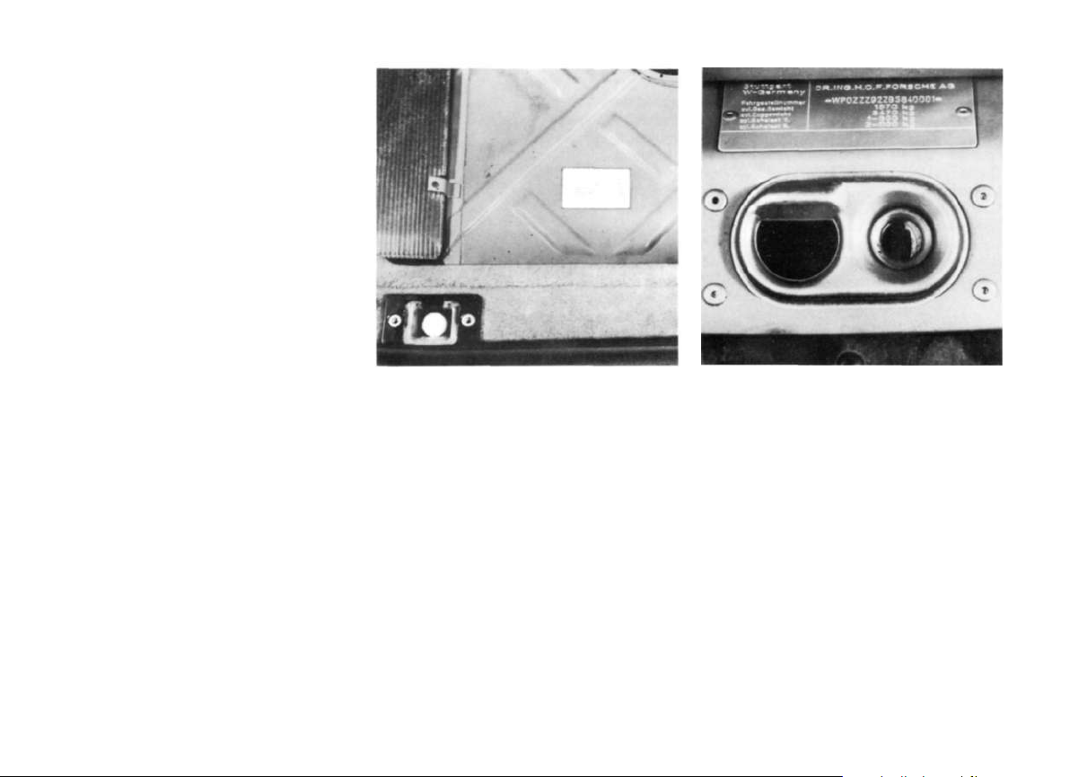
Location of Identification Plate,
Chassis Number, Engine Number
and Paint Number
When ordering spare parts or submitting
inquiries, always quote chassis and engine
numbers to ensure correct and prompt service.
6
Data bank
The data bank is fixed on the floor in the rear of
the luggage compartment next to the spare
wheel well.
Identification plate
The identification plate is riveted on the
front cross member, behind the bonnet lock.
Page 8
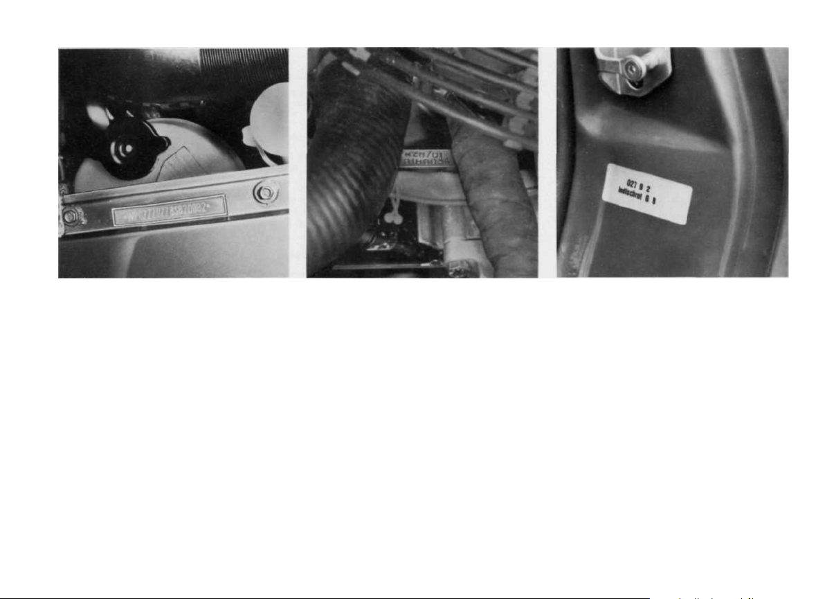
Chassis number
Engine number
Paint number
The chassis number is stamped on the top of
the right wheel arch in the engine compartment and is visible through a cut-out in the
wing flansch.
The engine number is stamped on the front
reinforcing rib in the top half of the crankcase.
The paint number plate is fixed on the left
hand door lock pillar.
7
Page 9
For your own safety, you should,
before a journey,
Keys
check pressures and condition
of the tyres
clean the windows and light lenses,
front and rear
turn the ignition on, and check that
headlamps and turn indicators
are functioning
take note of the central warning
light
adjust rear view mirrors to give
uninterrupted rear vision
fasten seat belts, so should
the passengers.
Have the oil level in the automatic
transmission checked regularly,
even in-between the recommended
maintenance intervals.
8
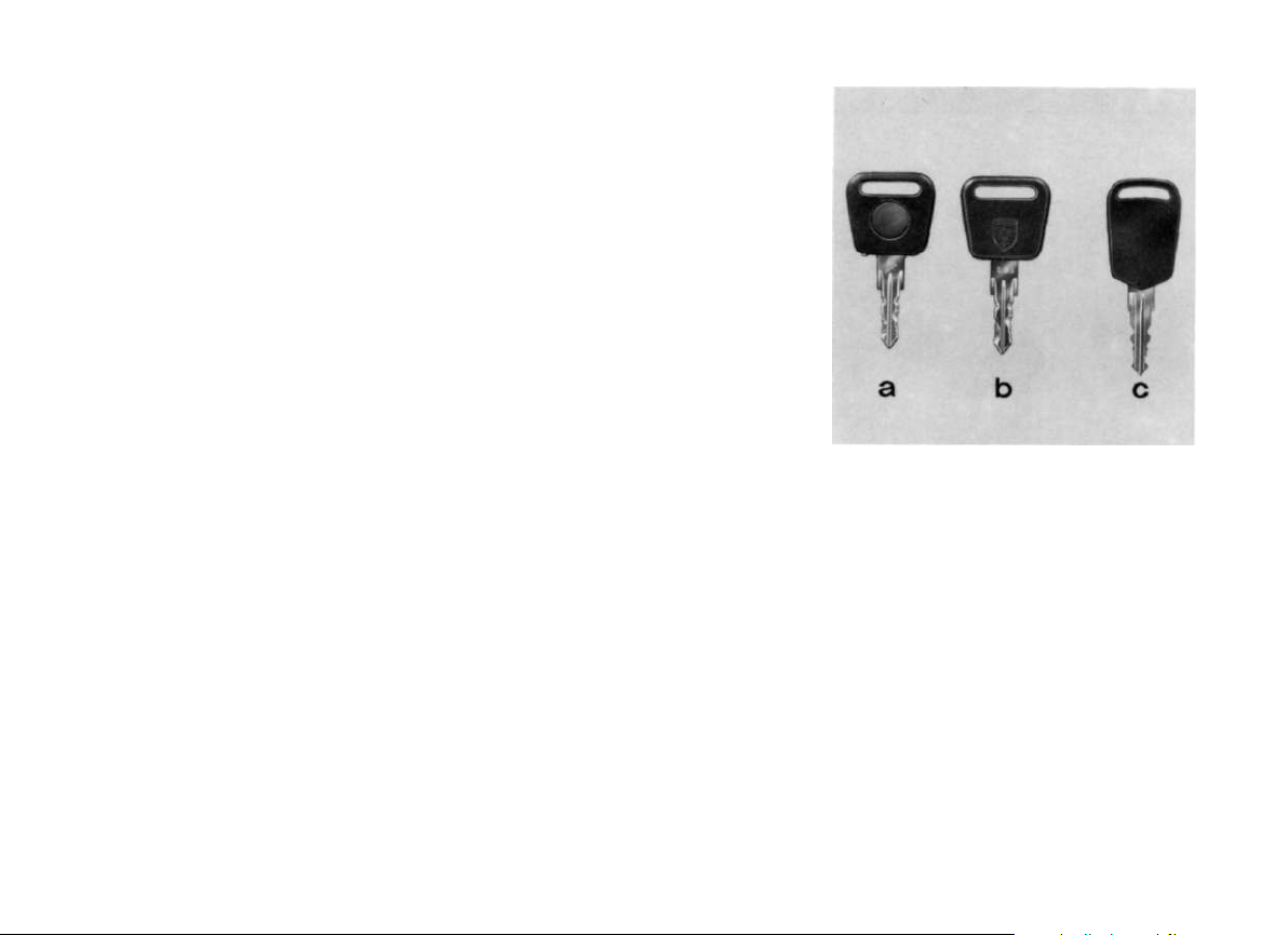
With the vehicle you receive two master and
two auxiliary keys. The two master keys fit all
locks, the auxiliary keys do not fit the glove
compartment lock.
Vehicles with a rear seat storage compartment receive two additional keys for the
compartment lock.
One master key has a built-in flash light. The
light is on as long as the contact button is depressed.
When the light begins to fade, the battery
must be replaced with one of the same type.
A discharged battery could leak and damage your clothing.
By virtue of the new format for the master
and auxiliary keys, the unauthorised manufacture of keys is almost completely elimi-
nated. This means however, that you yourself will not be able to get replacement keys
cut, you must order them from the manufacturer.
a Master key
b Auxiliary key
c Rear seat storage compartment key
Should you need new keys, you must give
the key number. This number is noted on
the plastic tab, that you receive with the
keys. Keep this tab somewhere safe, not in
the vehicle.
Page 10
Application Positions
Door Locks
Steering/Starter
ignition switch
Luggage
Compartment
Door Lock
Tank Filler Cap
Glove
Compartment
Switching Alarm system on and off.
Locking and unlocking the doors.
Lockable.
Switching alarm system on and off. Opening lug-
gage compartment door.
Only lockable with an auxiliary key.
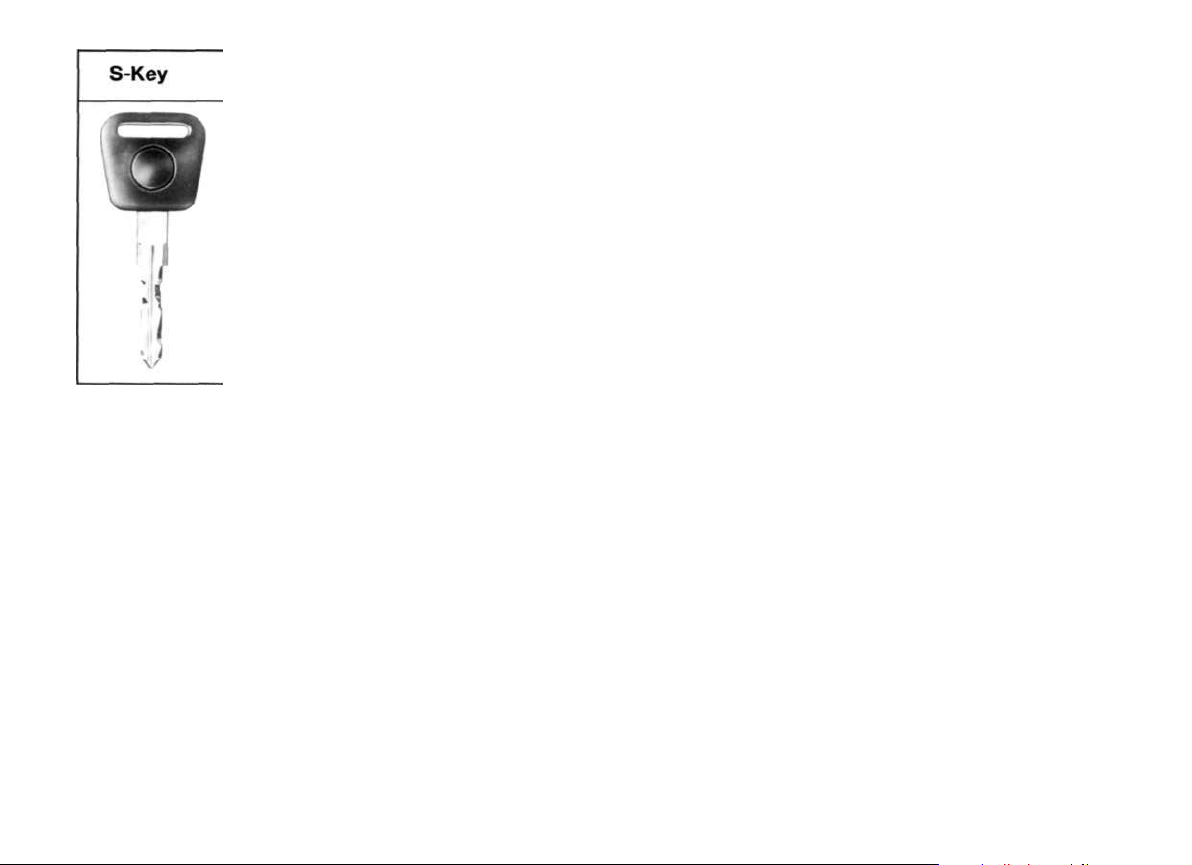
The S-Key should, for reasons of safety, not be
lent out to other persons
Lockable.
Alarm system
If your car is equipped with an alarm system
you will have received two S-keys instead of
the normal master keys. The alarm system
can be activated only with the S-key by locking the doors or closing the luggage compartment door and turning the key to the
left. If the doors are locked with the auxiliary
key then the door will be mechanically locked but there is no contact to activate the
alarm. The alarm system is switched off automatically when a door or the luggage compartment is opened with the S-key. If the luggage compartment door is opened while the
alarm system is switched on, the key must
be turned to the left to reactivate the alarm
system. If the drivers or passenger side door,
engine compartment hood or the luggage
compartment door is opened while the
alarm is activated a specially protected siren
will sound for about 30 seconds. The engine
cannot be started.
In the interest of safety the S-Key should never be lent out to other persons. For this reason the fuel filter cap can only be locked
with the auxiliary key. This key can be used
as a"workshop key" and can also be handed
over at filling and service stations.
9
Page 11
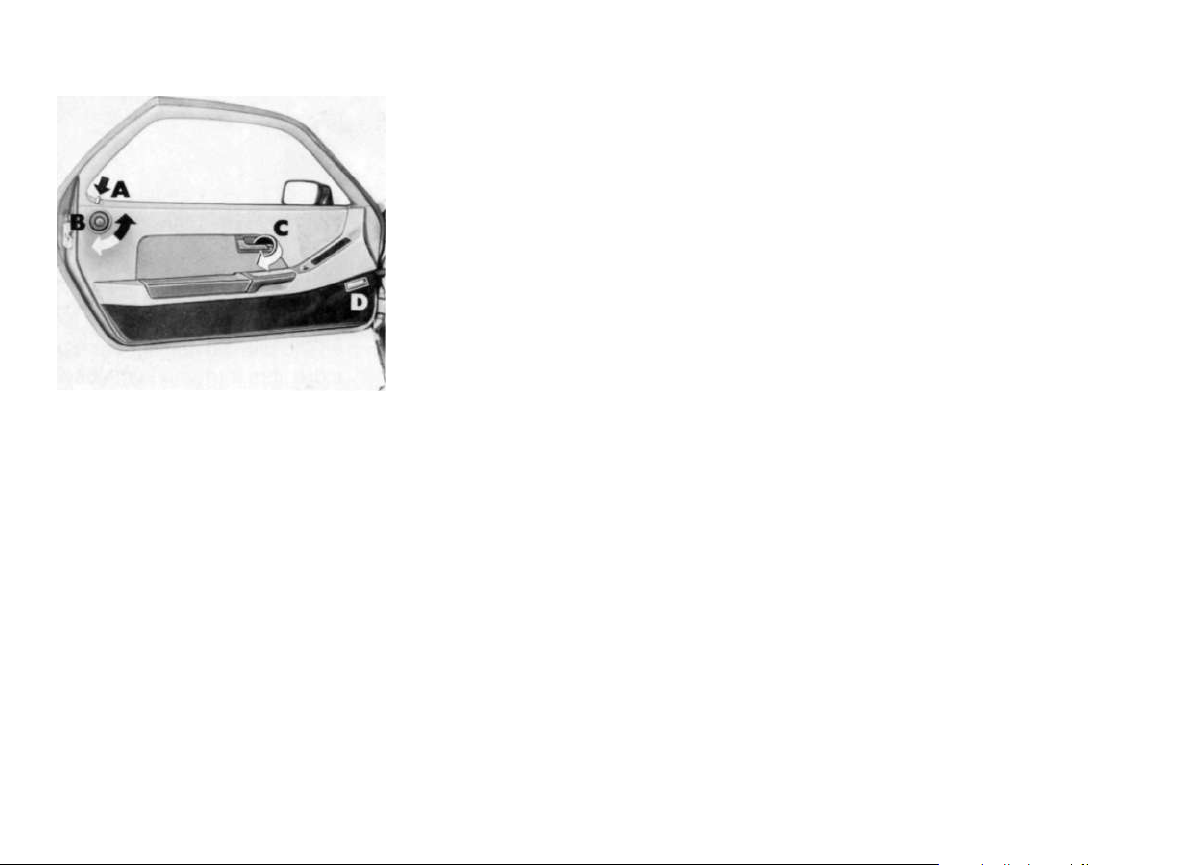
Doors
The doors are opened from the outside by
pulling the inset door handle, and from
inside, by pulling lever (C).
Access to the storage compartments in the
door is obtained by pressing the safety
knob, and tipping the armrest outwards.
The window regulators are operated by the
rocker switches in the middle console.
10
Warning: To avoid injury to unknowing occu-
pants of the vehicle, (e. g. children) by the
closing of the windows, the ignition key
should always be withdrawn when leaving
the vehicle, if only for a short period.
The footwell lights (D) mounted forward in
the lower part of the door trimcone on, with
the switch in the appropriate position, when
the door or the luggage compartment door
is opened. Each light can also be switched
on or off individually by means of the integrated switch.
Central door locking
By means of the central door locking system
both doors are electrically locked or unlocked by operating one lock.
When the doors are locked the locking buttons (A) must be fully retracted. If this is not
the case the lock on that door is not properly
engaged. Re-open the door, close it properly and re-lock it.
Page 12
On vehicles with central locking the passenger door can be locked and unlocked by
turning the knob (B) as well as with the key.
To prevent being accidentally locked out of
the vehicle it is impossible to lock the door,
while open, either using the knob (B) or with
the key.
Central locking is only possible when both
driver and passenger doors are closed. If
one door is locked before the other is closed
it will automatically unlock when the other
door is closed.
A mechanical locking or unlocking of the
individual doors is only possible when the
ignition is switched on or when the ignition
key is turned to pos. 1. This cut out of the
electrical function prevents the doors from
locking in the case of a short circuit or if
deformed in an accident.
When the ignition is switched off but with the
key still in the ignition lock the doors can be
centrally locked using either the key or the
knob (B).
Door guard lights
The door guard lights come on when a door
or the luggage compartment door is opened.
11
Page 13
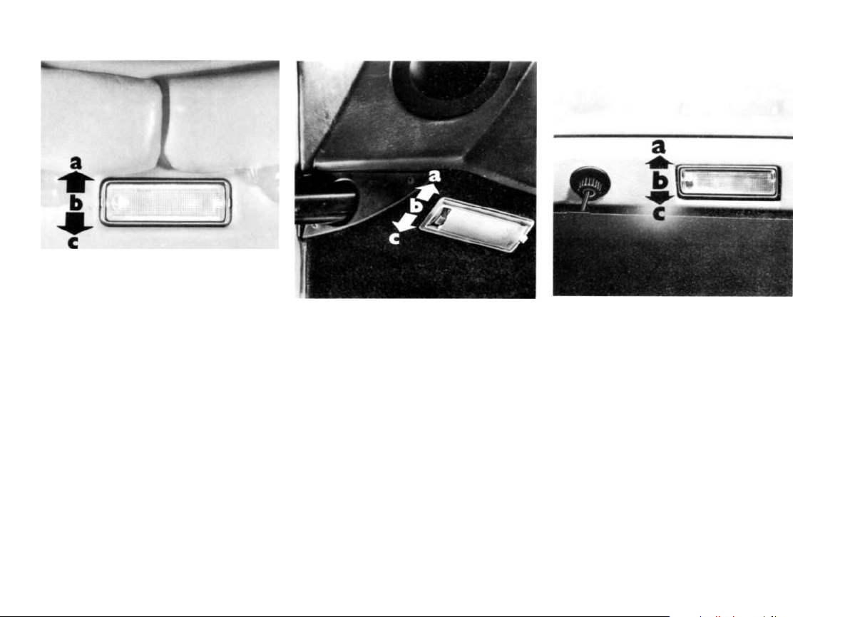
Interior lights
The interior lights, which are independent
from one another, come on, with the switch
in the appropriate position, as soon as a
door or the luggage compartment door is
opened. The interior lights mounted in the
roof lining can be switched as following by
tipping the light cover:
a - light switched on permanently
b - light switched off permanently
c - light comes on only when a door or lug-
gage compartment door is opened.
12
The footwell lights mounted forward in the
lower part of the door trim have following
switch positions:
a - light comes on only when a door or lug-
gage compartment door is opened
b - light switched off permanently
c - light switched on permanently.
The luggage compartment light in the rear
lid has the following switch positions:
a - light comes on only when a door or lug-
gage compartment door is opened
b - light switched off permanently
c - light switched on permanently.
Page 14
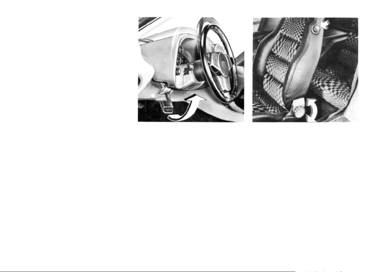
Front seats
Correct seat positioning is imperative for
safe and tireless driving. To enable individual
seating comfort, the seats are adjustable for
and aft and the backrest angle is adjustable.
To find the most suitable seat position, we
suggest the following procedure:
1 Pull the locking lever at the front of the
seat upwards, and slide the seat until your
leg is straight when fully depressing the
clutch pedal. You should not however
have to outstretch your foot to reach this
position. Let the locking lever down, and
ensure that the seat is locked in a ratchet
on the seat slides. Never try to adjust the
seat whilst driving, as a sudden change of
seat position could cause you to lose
control of the vehicle.
2 Grip the top half of the steering wheel.
Then set the backrest angle so that with
fully outstretched arms, your shoulders
still contact the backrest.
Then check the steering wheel position, and
view of the instruments.
For optimum legroom and view of the instru-
ments, the steering wheel and instrument
console can be released, adjusted, and then
re-locked.
The backrests are secured in position to
stop them tipping forward during braking; to
release, press the button on the side of the
backrest.
Similarly, the rear seat backrests can be released, and tipped forward, thereby giving
more luggage room in the rear.
13
Page 15
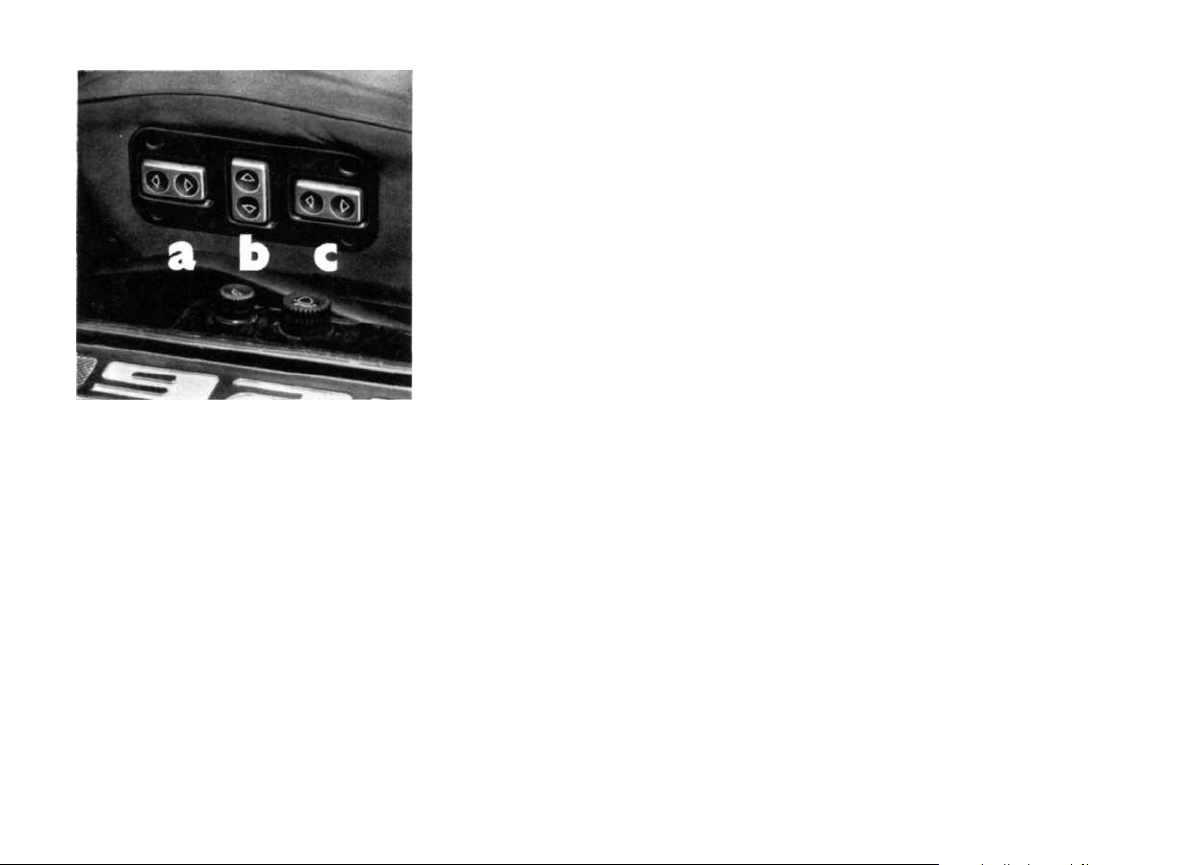
a - For and Aft adjustment
b - Height adjustment
c - Backrest adjustment
Electric seat adjustment Hand operation
In vehicles fitted with electrical seat adjustment, the controls for the electric motors
which adjust the seat for/aft, height, and
rake angle can be found mounted in the outside flanks of the seats.
14
To prevent damage to the belt lock and to
the seat cover, care should be taken that the
belt lock is pushed outwards so that it cannot jam between the seat and seat backrest
when the seat is moved forward.
Manual operation of the seat is also possible
in case of possible electrical malfunction. To
do this pull the locking lever at the front of
the seat upwards and slide the seat to
achieve the desired seating position, then
release the lever.
Page 16
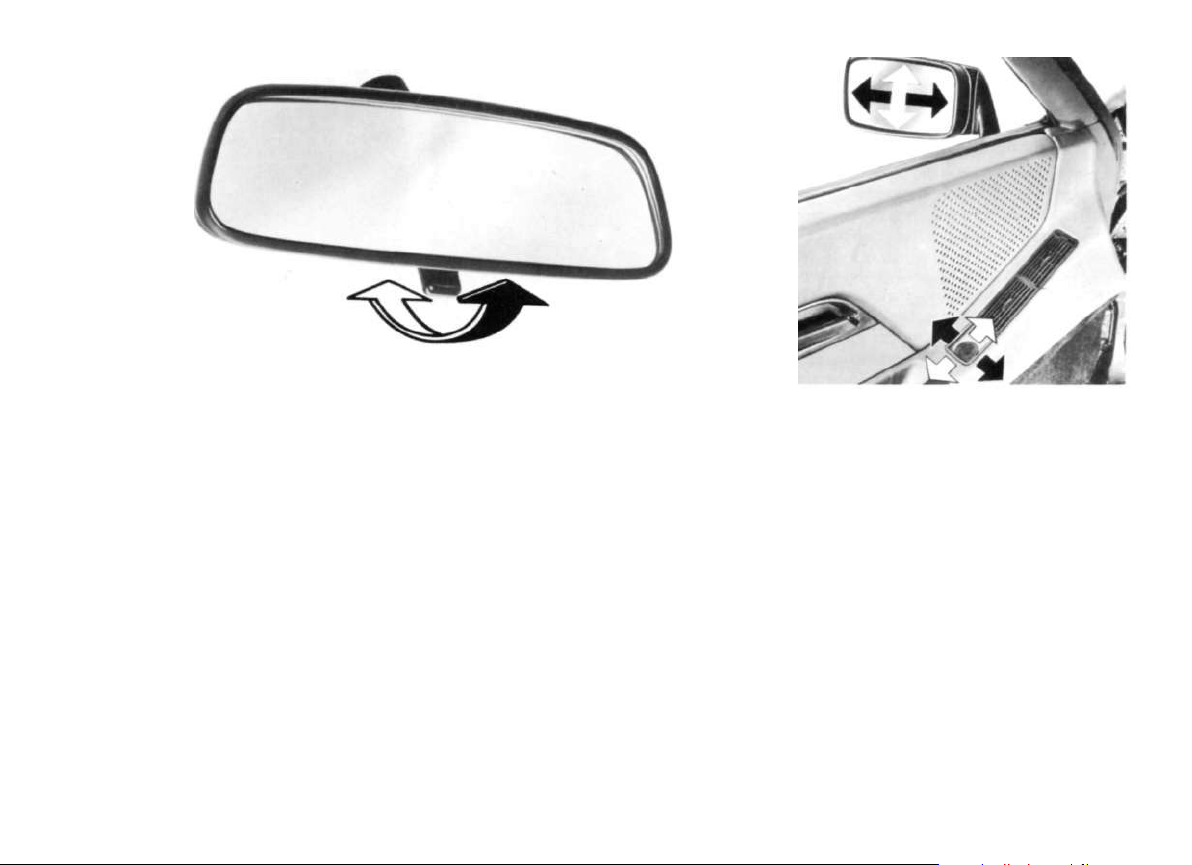
Rear view mirrors
Before beginning a journey you should ensure that the rear view mirrors are properly
adjusted.
The interior rear view mirror is stuck directly
on the windscreen. This enables a very short
mirror stem to be used thereby obviating
vibration, and a blurred image.
The mirror is adjusted to the anti-dazzle
position by pressing the lever underneath it.
The electrically adjustable wing mirrors can
be set with the switch in the driver's door.
The passenger door wing mirror is adjustable by the same switch, by pressing the
rocker switch beside the adjuster switch into
the appropriate position.
When necessary, the wing mirrors can also
be adjusted by hand.
The wing mirrors are also electrically heated
when the rear window heating is turned on.
15
Page 17
Safety belts
Your Porsche is equipped with safety belts
as standard fittings. All occupants of the car
should wear safety belts for their own safety,
on every journey. To remind you of this, a
warning light in the middle console comes
on for approx. 6 seconds, every time the
ignition is turned on.
The lap and shoulder belts as fitted are not
suitable for children under 140 cm (4 ft. 6
ins.) tall. To stop them distracting the driver's
attention, and for their own safety, children
under 12 years old should always travel in
the rear seats.
Never use one seat belt for two people.
Loose clothing affects the fit of the seat belt.
You should therefore take your coat off, because a correct seating position and freedom of movement are important for comfort
and safety.
Do not run the belt over fragile objects in
your pockets, e. g. spectacles, pens or a
pipe etc. as these could represent additional hazards.
Please remember when driving abroad, that
in some countries the wearing of seat belts
is compulsory.
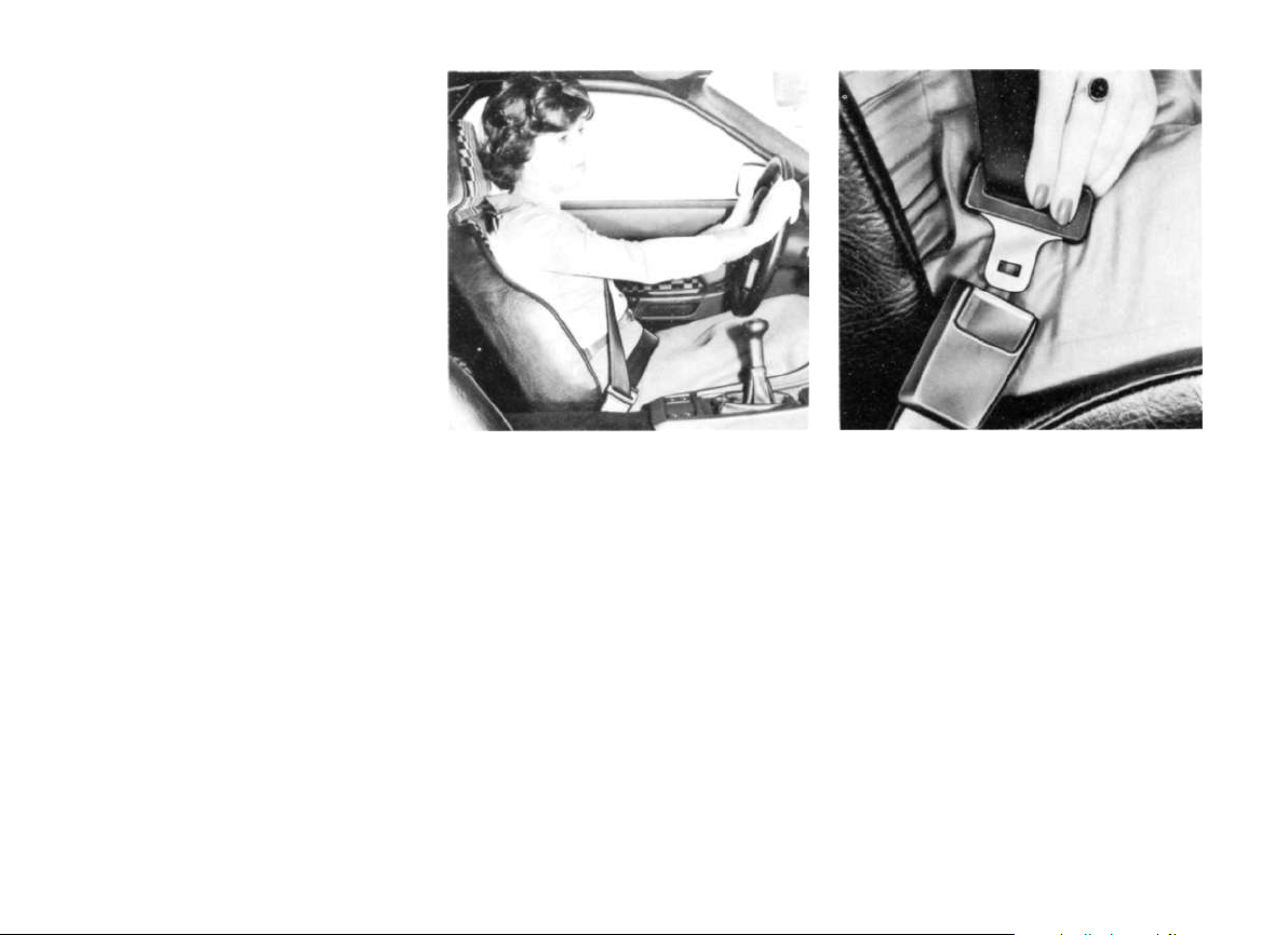
Putting on the belts
Decide the best seating position for yourself. Take hold of the sliding buckle and pull
the belt firmly over chest and hips. Press the
buckle into the respective anchor point until
you hear that the latch is locked. Slide the
plastic loop up to the buckle.
Avoid twists in the webbing when putting
on the belt.
16
Page 18
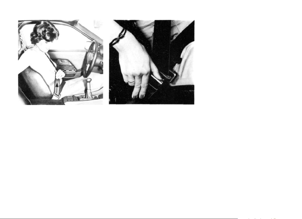
The lap part of the belt must always stay taut
over the pelvis. After putting the belt on, you
should therefore pull the shoulder part of the
belt upwards as shown in the picture. Now
and again during the journey, you should
repeat this procedure to ensure that the lap
belt is always taut.
The locking mechanism in the roll-up unit is
so designed, that by rapid acceleration or
braking, cornering or driving on steep in-
clines, the belt is locked. This locking system
reacts more quickly to the retardation of the
car than to any pull on the belt.
Releasing the belts
To release the belt, press the red button
marked "press". The buckle then springs out
of the anchorage, whether there is any loading on the belt or not.
Make sure that the belts are always fully retracted when not in use. This will prevent
them becoming dirty and avoid unnecessary damage to the belts themselves.
You should check your seat belts regularly
for signs of damage to the webbing. Make
sure that the locks and anchorage points are
in good condition. If the belts have been
subjected to high loads or stretched in an
accident, have them replaced in the interests of your own safety.
Back seat safety belts
The back seats are equipped with automatic lap belts. Do not twist the belt when putting it on. The belt is released by pressing
the red button.
Warning. Please do not make any alterations
or additions.
In case of doubt please consult your authorized dealer or, if you live in Great Britain contact
Porsche Cars Great Britain
26-30 Richfield Avenue
Reading
Berkshire RG1 8PH
17
Page 19

Footbrake
Clutch
Handbrake
The handbrake is cable operated to the rear
wheels only. It is applied by pulling the lever
upwards.
To release the brake, the lever must be pulled upwards whilst pressing the button in the
end of the lever until the ratchet is cleared,
and then letting the lever downwards.
The central warning light and the handbrake
warning light will go out when the brake lever
is fully released. (See Automatic warning
unit.)
18
To reduce the pedal effort necessary when
braking, your Porsche has a brake servo unit.
The vacuum necessary to operate this unit is
taken from the engine inlet manifold, when
the engine is running.
Please note that with a defective servo unit,
or when the vehicle is being towed with the
engine turned off, the braking effort required
is considerably increased as soon as the
vacuum reservoir is used up.
With properly bled and functioning brakes,
the free movement at the brake pedal will
remain constant. This free travel before the
brakes start to operate can be 20 mm (0.8
ins.).
Should this free travel suddenly become
bigger, either air has entered the system, or
one of the brake circuits has malfunctioned.
A malfunction of one of the brake circuits or
the loss of brake fluid would cause the central warning light to blink. (See Central warning unit.)
Due to the hydraulic operation of the clutch,
a free travel of the clutch pedal of 2.5 mm is
necessary.
Should this free travel suddenly become
bigger, it could mean a malfunction of the
clutch. Please consult your workshop for
rectification.
Page 20
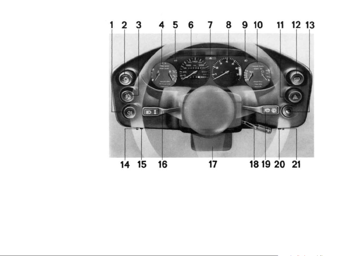
Instrument Panel
1 Rear fog lamp
(on vehicles without rear fog light:
buttton for re-setting trip meter)
2 Light switch
3 Front fog lamps
4 L.H. combination instrument
5 Turn flasher warning light
6 Speedometer
7 Central warning light
8 Rev. counter
9 Main beam warning light
10 R. H. Combination instrument
11 Hazard light switch
12 Heated rear window switch
13 Ignition switch and Steering column lock
14 Instrument panel illumination dimmer
control
15 Trip meter reset
(only on vehicles with rear fog light)
16 Turn indicator-Dipswitch-Parking light
and Headlamp flasher lever
17 Locking lever for steering column and
instrument height adjustment
18 Tempostat
19 Wiper - washer lever
20 Concentrated washer system
21 Wiper-delay adjuster
20
Page 21
1 -Steering unlocked, and all electrical cir-
cuits are operational except direction indicator - reversing lights, wing mirror ad-
justment, rear screen heating and fresh
air fan.
2 -Ignition is switched on. All circuits can
now be operated. With the motor
stationary, the central warning light and
the individual lights are on for control
purposes.
Steering lock and ignition switch
The ignition key has 4 positions:
0 -The steering is locked. All circuits con-
nected to the ignition switch are off.
This is the only position in which the ignition key can be withdrawn, and the
steering lock only operates after the key
is withdrawn.
The parking lights can be operated with
the switch in this position by using the
direction indicator lever.
20
3 - By turning the key to the right, the starter
motor is operated. As soon as the engine
fires, release the key. It will spring back
to position 2. With the engine running,
the central warning light and the other
warning lights should go out except the
brake warning light, which will go out
after the first application of the brakes
(see central warning unit). During the
operation of the starter motor, the items
with heavy electrical consumption, e. g.
headlights, rear screen heating, wipers/
washers, will be interrupted.
The starter motor should not be operated for
longer than 10-15 seconds. If the engine
does not fire, repeat the starting procedure
after a pause of approx. 10 seconds. Every
time the starter motor is operated, the key
must be returned to position 1 before trying
again, as a device is built into the ignition
switch to prevent inadvertent operation of
the starter motor whilst the engine is running.
Page 22

Starting the engine
neutral, but drive off immediately while
avoiding high rpm and full throttle until the
engine has reached its normal operating
temperature.
Warning: Never turn the key back to posi-
tion 1 whilst the vehicle is moving.
It is in your own interest to always remove
the ignition key when leaving the vehicle, if
only for a short period, and to ensure that
the steering lock is fully engaged. This is
done by rocking the steering wheel left and
right. This might also be necessary to re-
lease the lock when turning on the ignition.
When the engine is cold, component parts
being controlled in dependence of the temperature automatically provide the correct
fuel-air mixture required for starting.
Therefore, special starting instructions are
not necessary.
With a hot engine we recommend that
you fully operate the accelerator when starting. Do not allow the engine to warm up in
By cold weather, it is recommendable to
depress the clutch pedal when starting the
engine, even when the vehicle is in neutral.
Never start the engine or let it run in confined spaces. The exhaust contains the colourless and odourless gas, carbon monoxide, which is poisonous, even in small
quantities.
Please take note of the hints on running-in.
21
Page 23
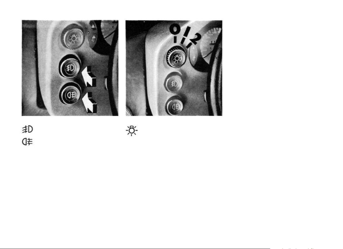
Fog lights
Rear fog lights
(on vehicles without rear fog light: .
button for re-setting trip meter)
The fog lights and the rear fog light can be
switched on in addition to the headlights by
pressing the respective switch. The lamp built
into the switch comes on when fog lights are
switched on. (The rear fog light operates only
when the front fog lights are switched on.)
Note: Take account of the varying laws in different lands controlling the use of fog lights.
22
Light switch
Switch in position 1: Sidelights
Switch in position 2: Headlights
In both of the switch positions the following
are also on: Backlights, Number plate lights
and instrument illumination. With the ignition
tion turned on, and the switch in position 2, the
headlights are elevated.
Instrument illumination
When the headlights are switched on the in-
strument illumination and Automatic gear selector illumination (vehicles fitted with automatic transmission) comes on automatically.
The illumination intensity of the instruments
is controlled by turning the knurled wheel
under the instrument panel.
Page 24
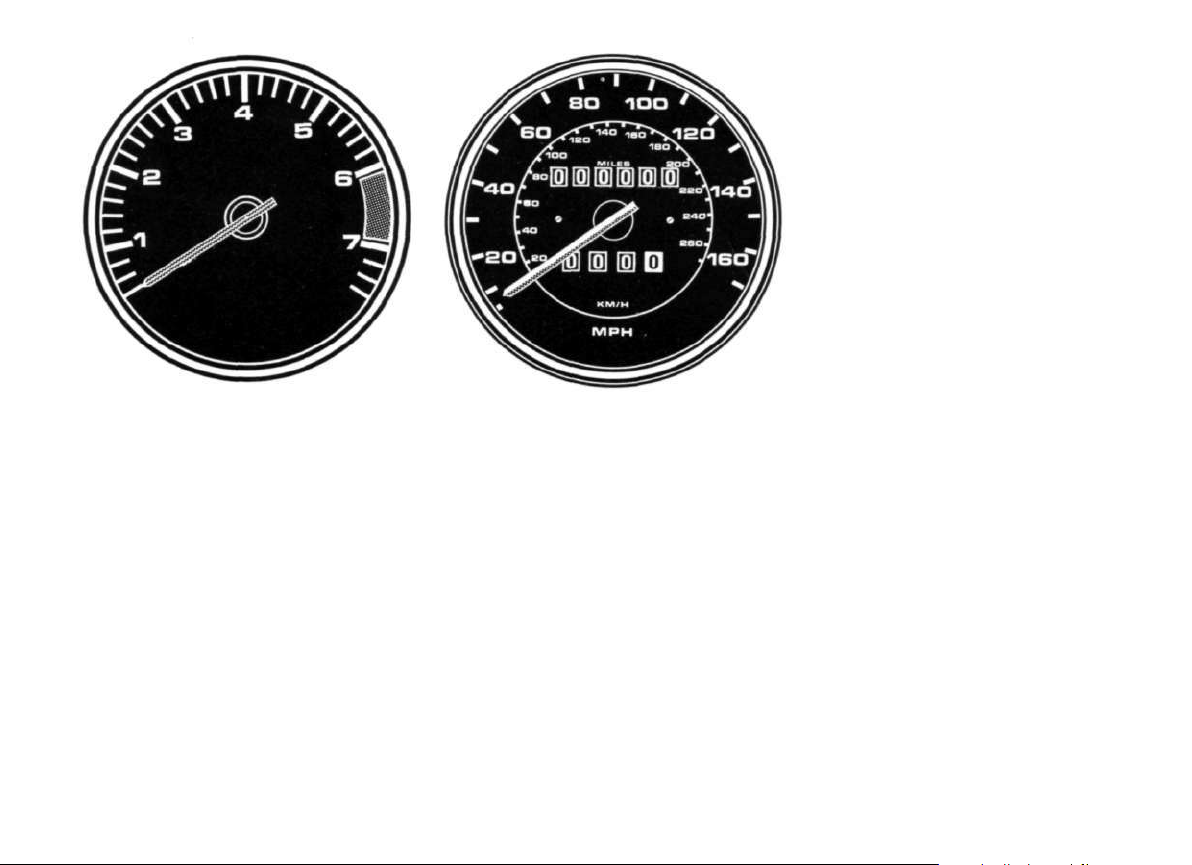
Revolution counter
Speedometer
The transistorised revolution counter indicates the number of thousands of revolutions per minute of the engine.
The red range on the scale of the instrument
is a visible warning of the maximum permitted revolutions per minute. Should you inadvertantly, during acceleration, exceed these
revolutions, a built in governor in the distributor cuts out the ignition current.
The electronic speedometer shows the
speed in miles and kilometres per hour.
The upper odometer registers the total mileage driven. The trip odometer can be set
back to zero when the ignition is on, by pressing the button under or in the left hand side
of the instrument console.
23
Page 25
Main beam warning light
Red Range-Warning
The main beam warning light in the instrument console lights when the headlamps
are on main beam. It goes out when dipped
beam is selected.
Blinker warning light
The blinker warning light flashes at the same
frequency as the blinker lights. Should one
of the blinker lights fail, the flashing is noticeably quicker.
Central warning light
The central warning light in the instrument
console lights when a fault occurs in one of
the systems in the vehicle. See "Automatic
warning unit".
Cooling fluid
Temperature Gauge
White Range - engine cold
Avoid over-revving the engine or labouring
Middle Range - normal
The temperature gauge needle should normally stay in this range. It is not unusual, when
the engine is being highly stressed, that the
needle tends towards the red range, but it
should return to the middle when the engine
loading is reduced.
If the needle goes into the red range it means
that the engine is being overloaded (by high
outside temperatures) and the warning light
will come on.
Warning light
If the warning light comes on, check that the
cooling fan is working. If the fan is not rotating,
the V-belt may be slack or broken; if so, it must
either be tightened or renewed. In cars with
air-conditioning, the electric fan located in front
of the air-conditioning condenser must also
operate. If it does not, there is a fault in the power supply or the temperature switch.
Allow the engine to cool down and drive to the
nearest authorized workshop, keeping a con-
stant check on the temperature gauge.
Avoid idling, crawling and engine speeds over
4000 rpm.
Consult the chapter on the cooling system.
24
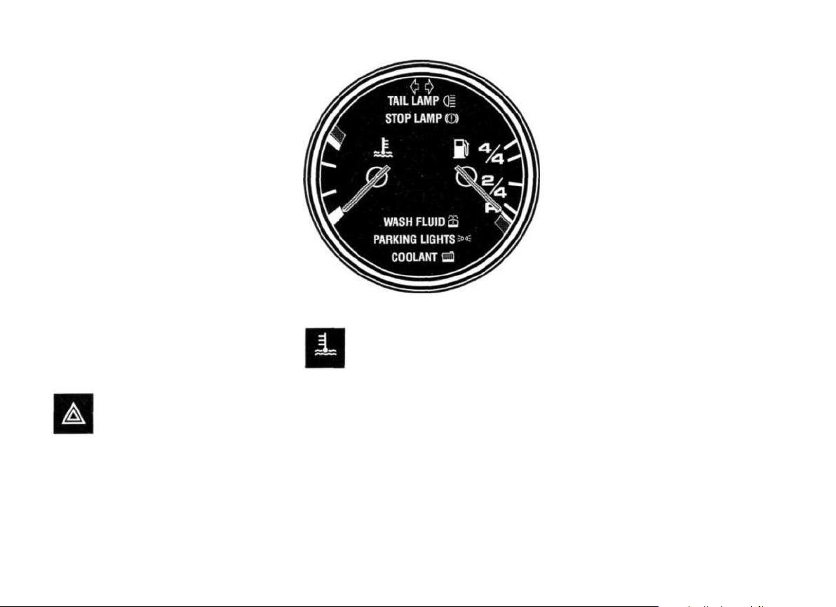
Page 26

Warning Lights
(see also Central Warning Unit)
TAIL LAMP
The warning light comes on when a tail light
ceases to function.
Consult the chapter on the cooling system.
PARKING LIGHTS
This light comes on in the Combi-lnstrument
when the sidelights are turned on and goes
out again when the headlights are turned on.
Fuel Gauge
With the ignition turned on the gauge shows
the amount of fuel in the tank. If the level is too
low the fuel warning light comes on.
Warning light
The warning light comes on when about 8 liters
(7 Imp. qts) are left in the tank. The tank should
be filled at the next opportunity.
STOP LAMP
The warning light comes on when the ignition
is switched on and must go out after the first
brake application. If a brake light bulb is defec-
tive the warning light will not go out.
WASH FLUID
The warning light comes on before the screen-
wash water runs out, indicating that about 2
liters (1.75 Imp. qts.) of water remain.
COOLANT
The coolant warning lamp lights up as soon
as the coolant level in the expansion tank drops
below the minimum permissible level. The
warning lamp may come on when the car is
started and then go out again after a short
time. This is due to the volume of the coolant
increasing as it warms up, and thus exceeding
the minimum permissible coolant level.
It is essential to top up the coolant and, if necessary, to have the cooling system checked
for leaks.
Trailer Indicator Light
The blinker warning light for the trailer operation flashes at the same frequency as the blinker lights. Should a trailer blinker fail the frequently is noticeably quicker.
25
Page 27
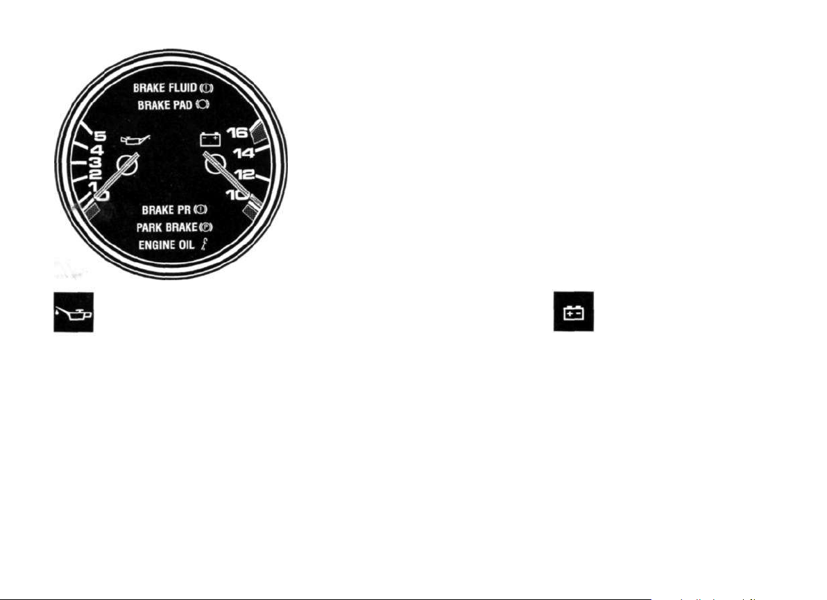
Oil Pressure Gauge
Voltmeter
Engine oil pressure is shown in bar. At 5000
rpm with the engine at normal operating temperature the oil pressure should be about 5
bar. A slight drop in oil pressure at higher temperatures is normal.
Should the oil pressure suddenly drop while
driving or should the red oil pressure warning
light come on, the engine should be turned off
immediately. If the oil level is correct the next
workshop should be called in to rectify the
fault.
26
Warning Light
The warning light comes on when the ignition
is turned on and goes out as soon as the cor-
rect operating pressure is reached. Should
the light come on during driving, this indicates
that the oil pressure is not correct.
In this case stop immediately.
If the oil level is correct the next workshop
should be called in to rectify the fault.
The voltmeter shows the overall condition of
the charging system. The needle should nor-
mally stay in the range 12-14 volts when the
engine is running. A temporary drop under 12
volts when starting the engine is normal.
Warning Light
The warning light checks the function of the
alternator. It comes on when the ignition is
Page 28

turned on and goes out as soon as engine rpm.
are high enough. If the warning light flickers or
comes on during driving, it can mean that the
fan belt is loose or broken. The fault could also
lie however in the regulator or the alternator.
In the latter cases the journey can be continued but only to the next workshop. Electrical
consumption should be kept to a minimum.
Warning Lights
(see also "Central Warning Unit")
BRAKE FLUID
The warning light blinks when the fluid level
drops below the allowable minimum.
BRAKE PAD
The light comes on when brake pads are worn
down to the allowable minimum.
BRAKE PR
The light blinks when one brake circuit fails.
PARK BRAKE
The light comes on when the handbrake is on
or not fully released.
ENGINE OIL
With the vehicle level and the ignition turned
on, the warning light will come on if there is
less than 6 liters (1.32 Imp. galls.) of oil in the
sump.
27
Page 29
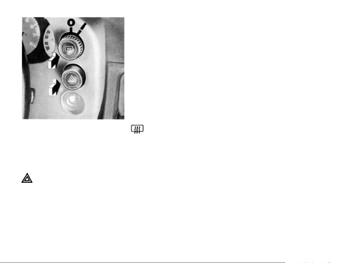
Rear screen heating
The heating for the rear screen and outside
mirrors is operated by the combined twistpush-pull switch in the instrument panel. The
switch is illuminated when the heating is on.
Switch in the pushed-in position
Hazard light switch
When the hazard light switch is operated, all
4 flashing lights flash simultaneously.
The hazard light switch is operative in any of
the ignition switch positions.
28
Switch in pulled-out position
0 - Rear screen heating off.
1 -Rear screen heating on. The heating is
so regulated that the rear screen will not
mist up.
0 -Full heating for de-icing. After approx. 15
minutes the heating turns off, automatically.
1 - Full heating for de-icing. After approx. 15
minutes a relay switches the heating
down to demisting power.
Page 30
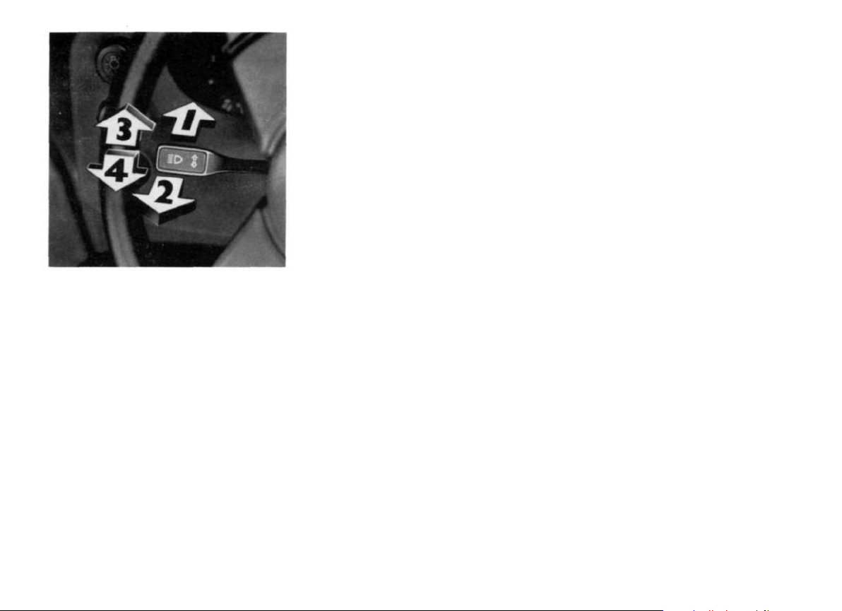
Direction indicator- Dip - Parking
light - Headlight flasher switch
This switch operates the headlight flasher, the
dipped and main beams, the direction indicators and the parking lights.
Direction indicator
Push the lever upwards beyond the overcentre position - Right blinker.
Push the lever down beyond the over-centre
position - Left blinker.
If the lever is only pushed to the over-centre
position, the blinkers only operate until the
lever is released.
The malfunction of a blinker light is apparent
by a faster flashing rate. The direction indicators only operate when the ignition is on.
With the ignition key removed, the lever in the
up position turns the right hand parking lights
on, and in the down position the left hand parking lights.
Parking lights are the front and rear sidelights
of the respective side.
Main and dipped beam
With the light switch in position 2, main beam
is selected by pushing the lever towards the
instrument panel, and dipped beam by pulling
the lever back towards the steering wheel. With
main beam selected, the blue light in the instrument panel comes on.
Headlight flasher
The headlight flasher is operated by pulling
the lever right back towards the steering wheel,
and the headlights stay on as long as the lever
is held in this position. The headlight flasher
operates also when the vehicle lighting is not
on.
29
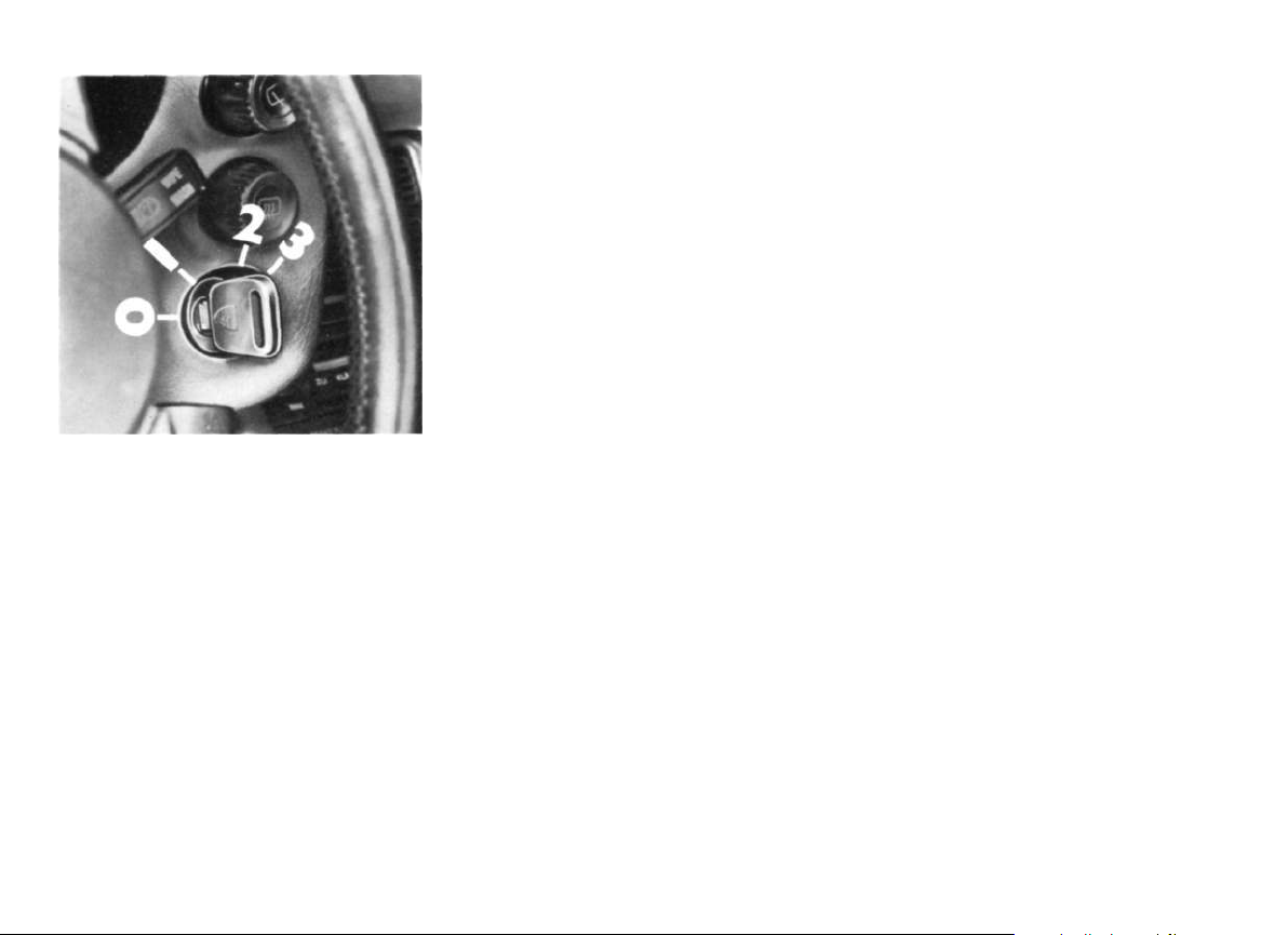
Page 31

1 Set/accelerate
2 Reset
3 Cancel
Tempostat
(Automatic speed control)
The Tempostat will maintain any desired
speed with the range 50-200 km/h (30 to
120 mph) without your foot being on the accelerator. Independent of this, you can
brake, change gear and accelerate as normal.
The operation of the Tempostat is controlled by the antenna lever behind the wiper
antenna.
The speed being travelled at any point in
time can be fed into the electronic control
unit by moving the lever forewards (position
1).
You can then take your foot off of the accelerator and this speed will be maintained.
By braking or stopping, the unit cuts itself
out, but the last speed fed into the unit remains registered. This registered speed can
be recalled by moving the lever downwards
(position 2). However, should the ignition be
turned off, the registered speed is cancelled from the unit.
If the registered speed is too low, you can
increase speed with the accelerator or by
moving the lever forewards to position 1 and
holding until the desired speed is attained,
and then letting the lever free. This speed is
now fed in to the unit and registered.
If the registered speed is too high, pull the
control lever towards the steering wheel
(position 3) or brake; this interrupts the Tempostat control, until the required lower
speed is attained, and then move the lever
forewards to position 1. Again this new
speed is registered and maintained.
Note: When you depress the clutch, the
speed control is interrupted, but when the
clutch is released, the speed control takes
over again.
To avoid accidentally overrevving the engi-
ne, do not move the gearshift lever into neutral at road speed above 50 km/h (30 mph)
while the cruise controle is engaged.
If you exceed the speed registered in the
control unit, e.g. during overtaking by using
the accelerator, as soon as you come off of
the accelerator, the registered speed will be
automatically resumed. On a steep incline
either up or down, it is possible that the vehicle will not maintain the registered speed
in a high gear, then you must change down,
to avoid labouring the engine by uphill, or to
ensure sufficient engine retardation by
down hill driving.
We do not recommend use of the tempostat
in heavy traffic or when road conditions are
unsuitable (eg. winding or slippery roads).
30
Page 32

5 Wipers and washers. By pulling the lever
towards the steering wheel, the electric
washers as well as the wipers are switched on.
6 Head lamp washers. By pushing the lever
towards the instrument panel, the headlamp washers are operated, but only when
the headlights are on. Refer to paragraph
on headlamp washers.
Wipewash lever
The wipewash lever has 6 switch positions.
0 Wipers off
1 Slow wipe
2 Fast wipe
3 Very fast wipe
4 Delay wipe. The wipers operate automa-
tically at regular intervals. The delay interval can be adjusted by turning the knurled
knob A under the right hand side of the
instrument panel.
The windscreen should be sufficiently wet
before the wipers are actuated to avoid
scratching it. The wiper blades should be
checked regularly, and replaced at least
once a year.
Concentrated washer system
With the concentrated washer system, even
dirt embedded in siliconbased polishes can
be removed from the screen.
A short press on the switch Β under the right
hand side of the instrument panel causes
the concentrated Porsche cleaning solution
to be pumped onto the screen. The duration
of the spray is controlled by a time relay to
avoid too heavy consumption of the solution. If necessary the operation can be repeated.
The windscreen washers and wipers can
then be operated to finish off the cleaning
process.
31
Page 33

Cockpit Layout
1 Side window demisting
2 Instrument panel
3 Air conditioning
4 Cancelling button for Auto. Warn unit
5 Center vent
6 Safety belt warning light
7 Glove compartment lock
8 First aid box holder
9 Wing mirror adjuster
10 Bonnet lock
11 Horn
12 Power window switch
13 Sunroof switch
14 Rear screen wiper switch
15 Selector lever
16 Clock
Page 34

Central Warning Unit
Priority 1 - The central warning light flashes
together with the individual warning light.
The following functions have priority 1:
Brake circuit failure, Brake fluid level, Oil
pressure, Oil level.
If a malfunction is indicated here the vehicle
must be stopped and turned off immediately. The fault must be rectified.
Functions that do not require immediate
attention are:
Priority 2 - The central and individual warning lights come on continuously.
The following functions have priority 2:
To increase driving and operational safety
an automatic warning system has been
developed, that shows the driver, via an
unmistakeable warning light that comes on
in the instrument panel, that there is a possible malfunction. This is done automatically
without the driver having to do anything.
The warning lights for the various functions
are located in the Combi-instruments.
32
Should a malfunction occur the central
warning light in the instrument console will
come on. At the same time the light for the
individual function will also come on, indicating what is malfunctioning.
The function control is divided into two
priority groups. Functions that are essential
for driving and operational safety are:
Brake pad wear, Hand brake, Cooling fluid
level, Cooling fluid temperature, Fuel tank
reserve, Screen washer water level, Brake
lights, Tail lights.
These functions show the need for part
replacement, re-filling, change of driving
mode or release of the handbrake, but not
for an immediate halting of the journey or
visit to a workshop.
Page 35

With the ignition turned on (engine not run-
ning) all individual warning lights and the
central warning light must come on to indic-
ate operational readiness. If the engine oil
level is too low the central warning light will
flash, (lack of engine oil can, in comparison
with all other functions, only be checked
with the engine turned off and with the vehi-
cle level.)
The warning light for the brakelights must go
out with the first brake application. The
remaining lights go out when the engine is
started.
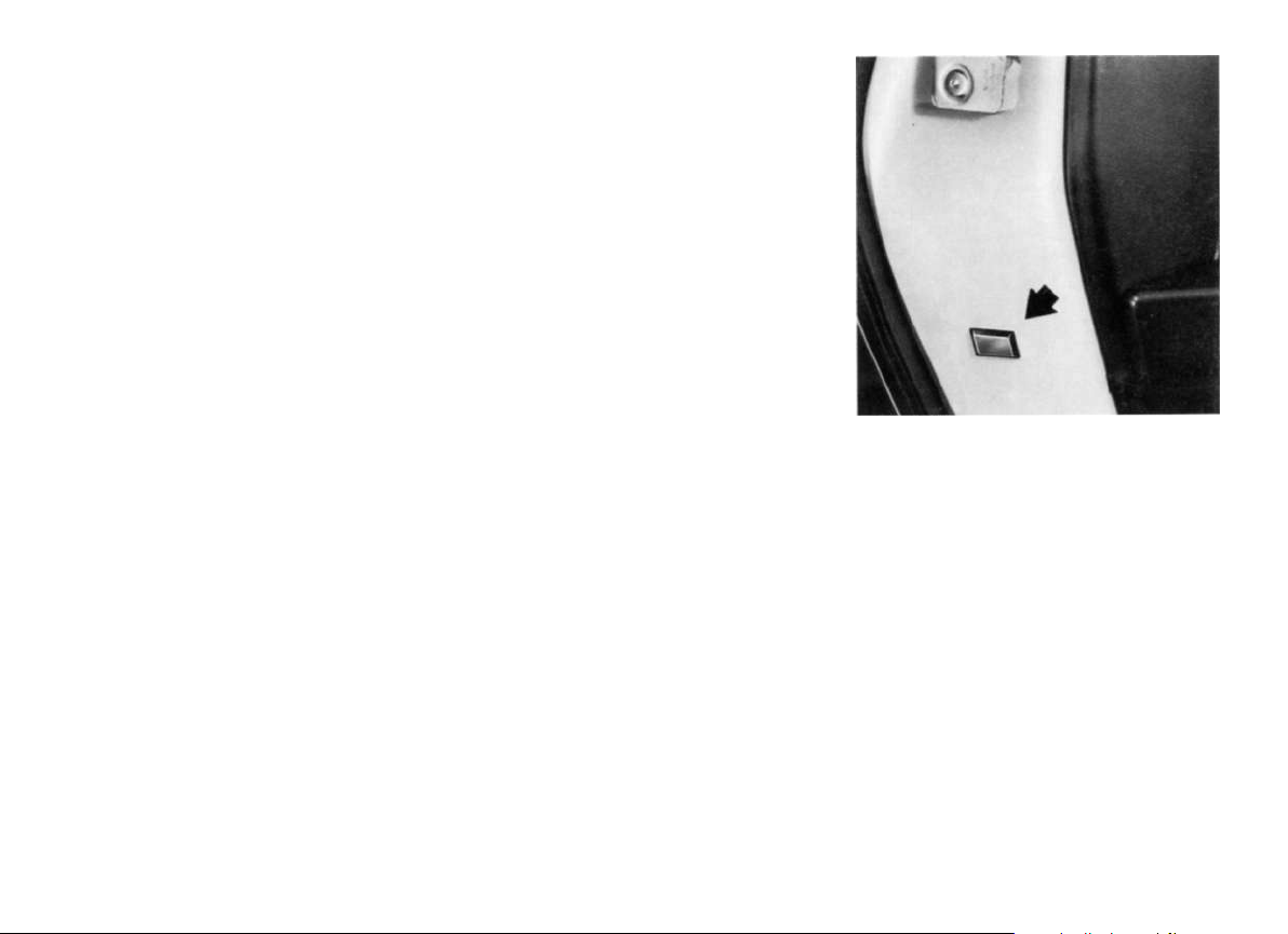
By pressing the button (arrow) in the middle
of the console the central warning light can
be turned off in the case of priority 2 mal-
functions. It cannot be turned off in priority 1
cases because immediate action is neces-
sary to rectify the fault.
When the handbrake is applied or not fully
released the central warning light cannot be
turned off. Only when the handbrake is fully
released does the central warning light go
out.
Note: If the vehicle is tow or roll started the
warning lights will not go out. The engine
must be turned off and restarted with the
ignition key.
33
Page 36

Ventilation grills
1 De-icing jets for windscreen
2 De-icing jets for side windows
3 Fresh air jets for passenger compart-
ment
4 Fresh air jets for footwells
5 Air jet in glove box
The height of the jet stream can be altered
by tipping the horizontal bars in the grill. The
lever in the grill adjusts the lateral air flow.
34
Central air inlet grills
The central air inlet grills provide ventilation
for the interior. If the air flow should become
uncomfortable the central air inlet grills can
be closed by means of a lever mounted at
the side of the grills.
In the defrost position the grills are closed
automatically.
Page 37

Side air inlet grills
To avoid misting up of the side windows, air
inlet grills are built into the door trim panels.
The direction of the air stream can be adjusted by the grills, and the airflow can be regulated by a lever.
A- Air inlet grill closed
B- Air inlet grill open
35
Page 38

Automatically controlled
air conditioning
The air conditioning only functions with the
engine running. The cooling effeciency is
dependent on engine revolutions. If more
cooling is required it is necessary - especially in city or stop-go conditions - to increase
engine rpm.
By automatically controlled air conditioning
the air conditioner compressor is switched on
automatically in position AUTO and Bl. The
engine runs at a higher idle speed in this position.
36
A maximum cooling effect is achieved with
the fan switch at pos. 4, the windows closed
and the side and center vents fully open.
When the air conditioner is switched on additional cooled air is fed via a vent to the glove compartment.
If the vehicle has stood for a long time in direct sunlight, it is recommended that the air
conditioning be turned on with the windows
open, to provide through ventilation.
The air conditioning must be operated for a
short period at least once a month.
This is especially important during the cold
weather when the air conditioning is not
needed.
This operation is necessary to lubricate the
expansion valve and the seals on the mainshaft.
Should the air conditioning become defective, that is to say if warm air comes from
the inlet grills, the air conditioning must be
turned off immediately or otherwise the
cooling compressor can be damaged.
Page 39

The automatic controls the temperature inside the car according to the programme
chosen and the temperature control lever
position.
The interior temperature is kept constant
even under changing climatic conditions.
Cold and warm air is blended automatically
by means of air mixer valves which are ope-
rated by a servo motor. The servo motor is
switched and controlled via inside and outside temperature sensors as well as the
coolant thermometer.
The following controls make an individual regulation of the air conditioning possible:
Temperature control lever for adjusting the
required interior temperature with temperature scale. The adjusted temperature is
equal to the temperature in the middle of
the vehicle interior.
As heat output is dependent on the coolant
temperature, the full heating capacity is delivered only after the engine has reached normal operating temperature.
Programme control lever to enable the automatic air conditioner to meet individual requirements several programmes are available.
Air conditioner and blower fan
switched off.
Automatic heater control. No cooling is possible on this position because compressor is switched off
for fuel ECOnomy. This programme is recommended when outside air temperatures are below
+5° C (40° F).
37
Page 40

An airstream is also
directed toward the windshield.
Automatic temperature control.
Heating and cooling (during normal
weather conditions). Air is distributed according to a predetermined
programme to suit the outlet temperature. The center vent may be
closed manually.
Same as position AUTO in addition
the defrost vents are opened. This
position is recommended during
wet and humid weather (rain, heavy
snowfall) to prevent the windscreen
from fogging up. It also provides
better cooling at head level and in
the footwells when outside air temperatures are very high.
Defrost position: provides fastest
possible defrosting of the iced or
fogged up front screen and side
windows. With this programme the
maximum heating effect and highest blower fan speed are switched
on automatically and the full air flow
is directed to the windscreen and
the side vents. The center vent is
closed automatically.
To prevent uncomfortable draughts, in positions the automatic control first comes into operation at coolant temperatures above approx. 45° C. Below
these temperatures the uncooled fresh air is
prevented from entering the footwell by a cold
start shut off device.
Blower fan switch
To provide air circulation when the vehicle is
standing still or at low speeds the blowerfan
runs at low speed even when the switch is in
the 0 position. Should you require increased
air flow the blower fan can be switched from
positions 1 to 4.
38
Page 41

Tensioning the V-belt
Checking cooling medium level
The tension of these compressor V-belt is
checked every 20.000 km. If the airconditioner is used frequently the V-belt tension
should also be checked between the service intervals.
The three mounting bolts (A) must be
loosened for tensioning the V-belt. Correct
the V-belt tension with tensioning nut (B)
and tighten the mounting bolts (A). The Vbelt is correctly tensioned when it can be
depressed approx. 5 mm using thumb pressure, between both V-belt pulleys.
Due to the fact that the system loses coolant it is necessary to check the coolant level
at the reservoir at least once a year.
Should air bubbles be visible at the inspection glass of the reservoir (arrow) for an
extended period, with the air conditioner
switched on, this indicates a lack of coolant.
Air bubbles will be normally visible for a short
time.
If necessary have the system re-filled in an
appropriately equipped service workshop.
39
Page 42

Headlight beam regulator
The height of the headlight beams can be regulated to the laden condition of the vehicle
with the knob (B). This enables maximum
road illumination without dazzling other road
users.
The normal headlight beam setting is obtained by turning the rotary knob as far as the
noticeable stop, i. e. the white dot must be
in line with "0" (see also "Headlight adjustment").
40
The beam setting must be corrected as
shown in the table when the vehicle load is
increased. Turning the knob clockwise raises the beams and vice versa. The correc-
tion should be checked by observing the
dipped beam cut-off (e. g. on the back of the
vehicle driving ahead of you).
Loudspeaker balance control
The volume of the loudspeakers in the door
and in the rear of the vehicle can be balanced by turning the loudspeaker balance control knob (A).
Page 43

Cigarette lighter
The element is heated by pushing the lighter in. When the correct temperature is
reached, the lighter springs out to the
normal position. With the lighter out, the
socket can be used for electrical auxiliaries
such as compressor or handlamp, with a
consumption of up to 120 watts at 12 volts.
Clock
The left-hand push-button beneath the display is used for setting the hour. The right-hand
push-button is used for setting minutes.
A brief press of a button (best done with a ball
point pen) will put the time forward by one hour
or one minute.
Prolonged pressure on the button(s) will cause
the hours and/or minutes to be displayed in
sequence.
In order to set the time accurate to the very
second, press the minute button at the very
moment you hear the time signal on your car
radio.
Ashtray
The ashtray is mounted in the middle console in front of the gear lever. To empty the
ashtray pull the tray upwards out of the
housing.
Rear seat storage compartment
The storage compartment is opened by
pressing the button and lifting the lid. For
security reasons, the storage compartment
is lockable.
On vehicles with a rear seat storage compartment a second ashtray can be found on
the tunnel in front of the compartment.
41
Page 44

Electric Sliding Roof
Manual Operation
The sunroof is operated by a spring loaded
rocker switch on the middle console. Appropriate movement of the switch opens or
closes the sunroof. When released the
switch returns to the neutral position and
the roof stops in the required position. The
drive mechanism is equipped with a safety
clutch which disengages when a certain
resistance is met, thus excluding the possibility of accidental injuries.
42
We do not recommend that the sliding sun
roof be operated at speeds in excess of 100
km/h. The force required to overcome the
resistance of the air pressure at higher
speeds can cause damage to the sliding
roof.
A hand crank is provided for manual operation in the event of an electrical failure. To do
this the cover of the sunroof drive must be
removed. Pull the cover down at the rear and
unhook the spring. Unscrew the now visible
slotted screw with the screwdriver tip of the
hand crank. Before inserting the fork-end of
the crank remove spacers which were under
the screw. Turn the knurled screw of the
crank into the threaded hole in the drive
Page 45

Rear screen wiper
shaft making sure that the lugs engage in the
slots. The roof can then be moved by turning
the crank.
If the roof is only about half open, it is recommended that you close the roof by turning
the slotted screw instead.
The rear screen wiper is switched on by a
press switch in the middle console. To prevent the rear screen from becoming
scratched it should be sufficiently wet
before operating the wiper.
The wiper motor is mounted in the bodywork
of the vehicle and not in the luggage compartment door, and drives the wiper with a
clutch, that disengages and engages automatically when opening or closing the door.
43
Page 46

Glove box
Sun visors
Make up mirror
The glove box is opened by pulling the
handle set into the lid. For security reasons,
the glove box is lockable.
44
The front sun visors can be either pulled
down in front of the screen or swung to the
side in front of the door windows to prevent
dazzle from the sun.
The rear sun visors can be swung back to the
rear window.
The make up mirror can be found on the rear
side of the passengers sun visor. On vehicles with leather interior a lighted make up
mirror is installed in the roof lining behind the
passengers sun visor (except on vehicles
with sun roof). By pressing the button the
mirror swings out from the roof lining.
Page 47

Luggage compartment door
(See notes under "Alarm system" if your car
is equipped with an alarm system.)
To open the door
Insert key into the lock and turn it to the right
and lift the door. Two gas-struts will then
open the door fully.
To close the door
Push the door down until it can be heard to
lock.
Never drive with the luggage compartment
door ajar or open, as then exhaust fumes
could enter the vehicle.
Engine compartment Hood top
To release the hood
Pull the lever on the left hand cowl side
panel underneath the instrument panel.
To open the hood
Lift the hood top slightly and release the
safety catch by pressing the lever upwards.
Make sure the windscreen wipers are not
tilted forward!
When the vehicle lights are on, a lamp on the
underside of the hood top lights automatically.
45
Page 48

Manual gearbox
The fully synchronised gearbox permits
rapid gear changes without the need to
double declutch. Be sure however that the
clutch is fully depressed before engaging or
disengaging a gear.
The gear positions are shown in the diagram
on the right.
46
Reverse should only be selected after the
vehicle has come to a complete stillstand.
To shift from 1 st into reverse gear, the gearshift
lever must first be moved into neutral position
between 4th and 5th gear.
With the ignition on, the reversing lights
come on automatically when reverse gear is
selected.
Permissible rpm before shifting down.
5-4 gear 4800 rpm
4-3 gear 4800 rpm
3-2 gear 4700 rpm
2-1 gear 4400 rpm
Page 49

Automatic gearbox
The automatic gearbox facilitates the driv-
ing of the vehicle. The individual gears are
selected automatically, depending on the
position of the gear selector lever, the
speed of the vehicle and the position of the
accelerator.
For safety reasons, the motor can only be
started with the selector lever in positions Ρ
or Ν.
The selector lever has six positions, and is
fitted with a mechanical lockout, to avoid inadvertent selecting of the wrong gear.
The lockout button must be pressed when
changing from
Ρ
R
Ν
?
. .. to
... to ...
... to ...
... to ...
. .
R
.
Ρ
R
1
At speeds in excess of 15 km/h (10 mph) a
hydraulically operated mechanical lockout
avoids changing into R or P.
The selectorlever console is illuminated.
Operation
Before selecting a gear with the engine run-
ning and the car stationary, either the handbrake must be on, or the footbrake operated. The brakes should only be released
when you wish to drive away, as the vehicle
will creep as soon as gear is selected. Do not
accelerate while selecting a gear.
At speeds in excess of 50 km/h (30 mph) Ν
should not be selected. Should however Ν
be selected inadvertantly during driving, the
accelerator should be released to allow the
engine to attain tickover revolutions, before
the gear is selected again. This avoids overloading the fluid clutch.
It is extremely important for correct functioning of the automatic gearbox, that the
correct fluid level is maintained. For this
reason you should check the fluid level frequently, between the normal servicing of
the vehicle.
If there is no automatic transmission fluid in
the gearbox or the torque convertor, the
engine must not be started, nor must the
vehicle be towed.
The automatic gearbox and the torque convertor are both filled with ATF, simultaneously. The back axle is filled with Hypoid oil. For
filling amounts see the chapter "Filling capacities".
47
Page 50

Selector positions
D
This is the gear to select for normal driving.
The three forward gears are automatically
engaged, according to the load on the
engine and the speed of the vehicle.
2
This is the gear to select for mountainous
terrain, as well as for long uphill or downhill
stretches. The engine's power is better utilised, and also the retardation affect of the
engine is greater. The vehicle pulls away in
1st gear and changes automatically into 2nd
gear. 3rd gear is locked out. During driving,
this position can be selected, even with the
accelerator depressed. However, as 2nd
gear is then immediately engaged, this
should not be done at speeds in excess of
150 km/h (90 mph).
1
This position should be selected when it ap-
pears advisable to hold the vehicle in 1st
gear, e. g. steep up or downhill stretches, or
when operating with a trailer in mountainous
terrain.
The vehicle remains in 1st gear, and 2nd and
3rd gears are locked out.
This position can be selected from position
2 during driving by pressing the lockout button, but should only be done at speeds
lower than 60 km/h (35 mph).
Ρ
Must only be selected when the vehicle is
stationary.
In this position, the driving wheels are mechanically locked. To select Ρ the lockout
button must be pressed.
Ρ should only be selected after the handbrake has been applied, and should be disengaged before the handbrake is released.
The engine can be started in this position.
Ν
In this selector position, no gears can be
engaged. It is the same as neutral in a man-
ual gearbox, and should be selected when
the vehicle is stationary for any length of
time, e. g. traffic jam. This position should
only be selected when the engine r. p. m. are
at tickover.
The engine can be started in this position.
R
This position must only be selected at tick
over, and with the vehicle stationary. The
lockout button has to be pressed to select
R. At speeds in excess of 15 km/h (10 mph) a
hydraulically operated lockout prevents R
and Ρ from being engaged. With the ignition
on, the reversing lights come on automatically when R is selected.
48
Page 51

Waiting Trailer operation
For short waiting periods, e. g. traffic lights,
the vehicle can be left in gear, and held stationary with the footbrake.
For longer waiting periods, with the engine
running, position Ν should be selected.
Never hold the vehicle stationary on a hill
with the accelerator. Always apply the hand
or footbrake.
This avoids unnecessary warming up of the
torque convertor or gearbox.
Stop start driving
For stop start driving, e. g. traffic jam, posi-
tion 1 should be selected.
Parking
When parking, or manouvering in confined
spaces, the speed can be adjusted with the
brakes, and very little acceleration is requir-
ed.
Selector position 2
For inclines, up or down, select position 1 in
good time, to attain maximum engine power
or retardation, and thereby reduce the loading on the brakes. For mountainous terrain
only use selector position 1.
Being towed
When the engine is not running, the oil pump
for the automatic gearbox is not driven, and
therefore the gearbox is not lubricated. The
following points must therefore be noted:
1. Selector
2. Towing speed must not exceed 50 km/h
(30 mph).
3. Maximum towing distance 50 km (30
miles).
4. For greater distances, the vehicle must be
transported on a trailer.
Tow or push starting
If your Porsche is fitted with automatic gearbox, it cannot be tow or push started.
in position N.
49
Page 52

The shift points given here are theoretical road speeds. There may be certain variations in practice as a result of ma-
nufacturing tolerances, the temperatures of components and automatic transmission fluid as well as tyre slip.
Up shifts
In selector position "D" the automatic up
and down shifts are dependent on a combination of road speed and accelerator pedal
position. The shift points vary between the
part throttle and full throttle positions.
50
A) When you drive with a gentle pressure on
the accelerator pedal the transmission
shifts from 1 st to 2nd gear approx. 30 km/h
(20 mile/h) and into 3rd gear approx. 45
km/h (28 mile/h) in order to preserve fuel
and reduce noise levels.
B) During full throttle acceleration or kick-
down the transmission holds 1st and 2nd
gears longer for better acceleration. It then
shifts from 1st to 2nd at approx. 100 km/h
(60 mile/h) and into 3rd gear at approx. 160
km/h (100 mile/h).
Page 53

The shift points given here are theoretical road speeds. There may be certain variations in practice as a result of manufacturing tolerances, the temperatures of components and automatic transmission fluid as well as tyre slip.
Down shifts
A) When you drive with gentle pressure on
the accelerator pedal the transmission
shifts down from 3rd to 2nd gear at approx.
35 km/h (23 mile/h) and into 1st gear at approx. 20 km/h (12 mile/h).
B) When you drive at full throttle the trans-
mission shifts down from 3rd to 2nd gear
at approx. 80 km/h (50 mile/h) to provide
better acceleration or hill climbing ability
on gradients and then shifts to 1st gear at
approx. 50 km/h (30 mile/h).
C) If you press the accelerator pedal down
beyond the pressure point to actuate the
kick-down switch, the down shifts take
place at higher road speeds to provide maximum acceleration. The down shift from
3rd to 2nd gear takes place at approx. 130
km/h (80 mile/h) and 1st gear is selected
at approx. 70 km/h (45 mile/h). The up-shift
points for kick-down acceleration are the
same as those given for full throttle acceleration.
51
Page 54

Tips for "Running-in" Maximum permitted revolutions Roof Racks
There are no particular rules to be observed
when "running-in" your new Porsche, however the following tips will be helpful in obtaining the optimum running properties.
Despite the most modern manufacturing
methods with their high precision, it cannot
be completely avoided that the moving
parts have to wear in with each other. This
wearing-in occurs mainly in the first 1000 km
(600 miles).
Oil consumption can be somewhat higher
than normal during the "running-in" period.
Therefore you should
never over-rev a cold engine, either in neutral or in gear,
continually change the demands made
upon the engine and transmission,
never exceed 5000 rpm in the individual
gears,
always change gear in good time, and thereby keep the engine in the optimum revolution range (note the Transmission diagram).
This of course also applies after running-in.
The red range on the rev-counter scale is a
visual warning.
When the maximum permissible engine speed
is reached, the governor built into the distributor cuts off the ignition current, and thereby
prevents the engine from being overrevved
during acceleration.
Bedding-in new brake pads
New disc pads have to bed-in, and do not
therefore have the full braking ability in the
beginning. To compensate for this reduced
braking ability for approx. the first 200 km
(120 miles) a little more pedal pressure is
necessary. This also applies after having the
disc pads renewed at a later date.
Please note: New tyres do not posess their
full road-holding ability. Therefore only
drive at lower speeds for the first 200 km
(120 miles).
Normal commercially available roof racks
cannot be fitted.
If an original Porsche rack (as available hitherto) is fitted, the permissible roof load is 35
kg. With the "New Porsche Roof Transport
System" you can transport a wide variety of
sports and hobby equipment, up to a roof load
of 75 kg. There are many different racks to
choose from.
Your Porsche dealer will be glad to advise you
on the versatility of the "New Roof Transport
System".
To ensure minimum noise, maximum econo-
my and a desirable level of safety when driv-
ing with an unloaded roof rack, you should not
exceed a maximum speed of 180 km/h.
When the roof rack is loaded, the recommended maximum speed depends on the nature, size and weight of the load. You should
not however exceed a speed of 140 km/h at
any time. Make sure that the load is firmly and
securely fastened.
52
Page 55

Tips for winter operation
Engine oil Cooling fluid
Before the onset of the colder weather, have
the engine filled with oil of the correct viscosity. See chapter on "filling capacities".
Battery
The battery capacity drops with lower temperatures, but the demands made upon the
battery generally increase. Therefore, have
the battery checked and charged, if necessary, in good time. Also have the acid content checked, and the terminals greased.
See chapter "Check and care of battery".
Corrosion protection
The salt spread on winter roads can have a
detrimental effect on your car's bodywork.
You should therefore wash the car as often
as convenient in accordance with our care
instructions. Have a preservative applied
and the underseal checked in an authorized
workshop before and after the cold weather
season.
The vehicle should not be driven without
anti-freeze at temperatures below freezing
point. The all-season cooling fluid in the
cooling system, put in by the manufacturer,
offers protection down to -30°C (Northerly
lands -40°C).
Nevertheless it is advisable to have the cooling fluid checked to make sure that the necessary protection is afforded, at the onset
of colder weather. When necessary, top up
with antifreeze. For amounts see chapter
"Filling capacities".
Brakes
After driving for extended periods on salt
covered roads a film can form on the brake
discs and pads which considerably reduces
friction and thus the braking effect.
Door and window seals
To prevent the freezing of the rubber seals
on the doors and hood top, they should be
treated with talcum powder or glycerine.
Door locks
To prevent the door locks freezing up, the
lock cylinders should be masked when
washing the vehicle, to avoid ingress of
water. Should however the locks still freeze
up, a proprietory de-icing solution can be
used to free them. A warmed-up key can
also be useful, but never use force.
53
Page 56

Water reservoirs
To ensure the function of the screen and
headlight washers under frost conditions,
anti-freeze should be added to the water. A
mixture of one part household spirit to three
parts water also works very well.
Winter tyres and snow chains
Due to the reduced effectiveness of summer tyres in winter we recommend the fitting of special winter tyres when snow and
ice are expected.
If M + S tyres are used in the winter, they
must be fitted to all 4 wheels. Be acquainted
with the different laws in different lands governing maximum speeds with these tyres.
54
Snow chains can only be mounted on the
driving wheels, and only the fine link chains
recommended by Porsche for the normal
series tyres should be used. This ensures
that the clearance between the wheel and
wheelhouse is maintained. However, note
the chain manufacturers recommendations.
Your authorized dealer will be pleased to
advise you in choosing the appropriate winter tyres and snow chains.
Additional equipment
It can be helpful during winter to keep a
handbrush and scraper in the vehicle, to
clear the screens of ice and snow, as well as
a board to put under the jack and some dry
sand to help traction when pulling away on
icy slopes.
Page 57

Car care instructions
Regular and correct care helps to maintain
the value of your car and is also a precondition for the long-life guarantee.
Washing
The best method of protecting your car from
the damaging effects of the environment is
frequent washing and the re-application of a
preservative.
The salt spread on winter roads, road dust
and dirt, airborne industrial emissions, dead
insects, bird droppings etc. can have a damaging effect on the bodywork if allowed to
remain on the car for a long time.
Salts have a particularly corrosive effect on
body seams, flanges and joints.
It is therefore necessary to clean such areas
thoroughly with a sponge when you wash
the car - or after going through an automa-
tic car wash, then rinse them with water and
rub dry with a leather.
New cars should be washed carefully with
plenty of clear water to protect the fresh
paintwork. Dark paint finishes show up the
smallest of surface damage (scratches) mo-
re readily than light colors. Dark colors are
also slightly more susceptible to scratches
because the composition of their pigments
and therefore require special care and attention.
Use an abundant supply of water, a soft
sponge or wash brush and a suitable, mild
car shampoo. Begin by spraying the body
thoroughly with water to rinse away loose
dirt. Do not wash your Porsche in bright sun-
light or while the bodywork is still hot. After
washing, rinse the car plenty of water and
then leather dry. Remember to clean the
seams, flanges and joints!
Do not use the same wash leather for rub-
bing down as you use for cleaning the windshield and windows.
The moisture which gets on to the brakes
during a car wash can reduce braking efficiency or make the brakes pull unevenly. Always test the brakes a few times after wash-
ing your car to make sure they are properly
dried off.
Dust should never be wiped off the car with a
dry cloth since dust particles are abrasive
and could dull and damage the surface finish.
Preservation
The paintwork contains certain fats which
maintain its high lustre and prevent it becoming brittle. Climatic effects can remove
these fats from the paintwork. This should be
counteracted by applying a paint preservative in good time to restore the fats and thus
retain the high lustre.
Please use only the preservatives and washing agents recommended by your Porsche
dealer. Provided it is washed and treated
with preservative regularly, the brand new
finish of your car will be retained for years to
come. Apply the paint preservative after the
car wash and polish it dry to obtain a bright
finish or simply add a preservative to the fi-
nal rinse water and rub down with a leather.
Polishing
The use of polishes is recommended only after it becomes evident that the normal preservatives no longer produce the desired finish.
Caution: Do not apply silicone polishes to
the windshield or windows.
The paintwork of your car is exposed to all
manner of mechanical and chemical stres-
ses, particularly climatic ones such as bright
sunlight, rain, frost and snow. Ultraviolet
light, rapid changes in temperature, rain,
snow, industrial dust and chemical deposits
constantly attack the paint which is only able to withstand such exposure in the long
term if it is given regular care and attention.
Matt painted parts should not be treated
with preservatives or polishes as this will
spoil the matt effect.
55
Page 58

Spots and stains
Tar stains, grease, oil spots and dead insects
cannot always be removed by washing alone. They can cause discoloration if allowed
to remain on the paintwork. They should
therefore be removed without delay with a
suitable cleaner (tar, stain or insect remover). Wash the affected area immediately after treating it.
Minor paint damage
Minor paint damage, such as scratches, scores or chips caused by flying stones, should
be covered immediately with paint before
corrosion sets in. However, if there are already traces of corrosion they must first be removed carefully and thoroughly. Coat the
area with a rust-proofing primer (applicator
or aerosol) and finish off with a top coat. The
paint code and color number are found on a
label close to lock on the left door pillar.
Undersealing
The underside of the car is durably protect-
ed by a factory-applied undersealing material.
As it is not possible to exclude the risk of da-
mage to this protective coating in day-today driving, it is advisable to have the underside of the car inspected at certain intervals
- preferably before the start of the cold season and again in the spring - and the undersealing repaired as necessary.
The oil industry has developed undersealing
and rust-proofing compounds based on bitumen or wax. Unlike conventional spray
oils, these preservatives do not attack the
anti-drumming materials applied at the factory.
Before applying fresh underseal, carefully
remove deposits of dirt and grease. Once it
has dried the new undersealing compound
forms a tough protective coating which provides efficient rust-proofing of the floor panels and components.
Always apply a fresh coating of suitable
preservative to unprotected areas after
cleaning the underside of the body or the
engine or carrying out repairs to underbody
components.
Your Porsche dealer is familiar with the bodyseal treatment procedures and has the
necessary equipment for applying factoryapproved materials. We recommend that
you entrust him with all such work and inspections.
Cleaning and preserving engine compartment
The engine compartment and the surface of
the engine are treated with a corrosion inhi-
bitor at the factory. If grease solvents are
used for cleaning the engine compartment
or the engine itself, they invariably destroy
the corrosion inhibiting coating. It is then absolutely necessary to have a durable preservative applied to all surfaces, body seams,
joints and components in the engine compartment.
Grease the return springs of the accelerator
cable after every engine wash.
Effective rust-proofing is particularly important during the cold weather season. If the
car is driven frequently in areas where salt
has been spread on the roads, the whole en-
gine compartment should be cleaned tho-
roughly after the cold weather season to
prevent the salt causing any lasting damage.
A full underbody wash should be performed
at the same time.
Windows
The road dust which settles on the windshield and windows contains particles of tire
rubber and oil residue. The interior trim and
upholstery gives off deposits, particularly in
strong sunlight, which collect on the insides
of the windows. These deposits are aug-
mented by impurities in the air which enter
the car through the fresh air vents.
A luke-warm soap and water solution or a
normal window cleaner can be used for
cleaning the insides and outsides of win-
56
Page 59

dows. Remember to clean the wiper blades
as well. If you use a chamois leather for the
windows, do not use it for the paintwork as it
will otherwise pick up a certain amount of
preservative or polish and could smear the
windows and thus impair vision. Use a special sponge for removing dead insects from
the windshield.
In winter a cleaning and anti-freeze agent
must be added to the water used by the windscreen washer system. These agents are to
be added in the ratio specified by the manufacturer.
Lights, plastics
Use only a soap and water solution for cleaning the plastic light lenses. Never use chemical cleaning agents for this purpose. The
same applies to other plastic parts and finishes.
Door, lid and window seals
Rubberseals tend to age and become brittle
or crack if they are not treated occasionally
with glycerine or talcum powder.
Aluminum wheels
Pitting can occur if metallic particles which
cause contact corrosion (e. g. brass or copper in brake dust) are allow to remain on the
aluminum for too long.
Regular care is necessary in order to retain
the attractive surface finish. The wheels
should be washed down with a sponge or
wash brush about every two weeks. In areas
where salt is spread on winter roads or there
is a lot of airborne industrial dust, it is best to
clean the the wheels weekly. Non-acidic cleaning agents with a maximum pH of 10 may be
used for this purpose.
Every three months you should coat the
wheels with a non-corrosive grease (vaseline) after cleaning. Use a clean cloth to thoroughly rub the grease into the surface.
Polishes which dissolve oxide, as frequently
used for other metals, or abrasive tools or
agents are unsuitable because they break
down the paint-resp. oxide film.
57
Page 60

Leather care
Cleaning is best performed with a white, soft
woolen cloth and a weak soap and water solution. Don't use aggressive cleaners and
rough cleaning materials. Take special care
not to dampen the other side of perforated
leather trim. Once you have cleaned the
leather (especially the very stressed leather
seats) treat it with »Karneol« preservative Porsche part-No. 000.043.007.00 -. Ask your
Porsche dealer for further details.
Care of seat belts
If it becomes necessary to clean the belts,
you can use any mild washing agent. Allow
the belts to dry, but avoid direct sunlight. If
unsuitable cleaners are used or any attempt
is made to dye or bleach the belts, the webbing may be weakened and thus constitute
a safety risk.
Leather should be cleaned and treated several times a year, depending on how quickly it becomes dirty. We recommend that
"Karneol" be applied initially after the first
few weeks or after the car has covered a few
thousand miles.
The natural surface markings of leather
skins, such as creases, healed scratches, insect bites and slight variations in shade and
grain add to the attractiveness of the real
leather product.
Fabric upholstery, carpets
Use only a vacuum cleaner or a medium stiff
brush. Remove stains and spots with a lukewarm soap and water solution or a reputable
spot remover.
58
Cleaning the antenna
To ensure perfect radio reception and smooth
action, the telescopic antenna must be cleaned regularly (weekly) with a soft cloth moistened
with oil. Operate the antenna several times
while cleaning it. Use only light, non-resining
oil, e.g., sewing machine oil, or special antenna cleaning cloths.
Storing your car
If you intend to store your Porsche for a prolonged period, please consult your Porsche
dealer. He will be glad to advise you on the
most suitable and necessary methods of
corrosion protection.
Page 61

Advice on maintenance
and breakdowns
It is strongly recommended that all the ne-
cessary work on your vehicle be carried out
by authorised workshops. The training and
experience of the workshop personnel, the
technical information from the manufacturer
and the special tools and apparatus provide
a good basis for the correct treatment of
your Porsche.
When, however, you wish to work on your
vehicle, this should only be done with great
care. Only then, is the safety of your vehicle
ensured. The engine should always be turned off and cool, before starting work on it.
Before undertaking an oil-change on your
vehicle, you should know how to dispose of
the old oil. Under no circumstances should
it be tipped into the drainage system, over
the ground or into the waterways. If you
cannot dispose of the oil properly, then let
your workshop do the oil-change.
Tool-kit
The tool-kit is in the tray fitted to the back panel
of the vehicle. To remove the panel covering
the tool-kit, both knobs must be turned through
90°. It contains all the tools necessary to remedy small faults and to enable you to do your
own servicing. The jack is by the spare wheel.
Some lands require that additional tools and
replacement parts be carried in the vehicle.
Please enquire before driving abroad.
The jack supplied with the vehicle should
only be used when changing the wheels on
the vehicle. When working under the
vehicle, it should be supported on purpose-
made stands for safety.
59
Page 62

Engine oil level
The oil level should be between the two
marks on the dipstick. If the oil level sinks
below the lower mark, the central warning
light will flash when the ignition is turned on.
(See Central warning unit.) The actual oil
level can only be determined however when
the vehicle is standing horizontal.
It is incorrect to check the oil level immedia-
tely the engine has been turned off,
because the circulating oil takes a few
minutes to flow back to the sump. If the level
is on the lower mark, only enough oil should
be added to ensure that the level does not
fall below this mark before oil is checked
again. When the engine is heavily stressed,
as in summer on the motorways with constant high speeds, or in the mountains, the
oil level should be maintained near the
upper dipstick mark as the oil has more cooling to do.
60
Checking oil level
1. Pull dipstick out and wipe with clean cloth.
2. Push the dipstick fully in, and then pull out
and read the level. The difference bet-
ween the upper and lower marks is approx. 1,5 liter.
Topping up engine oil
1. Unscrew
2. Top up with an oil of the same quality and
of a recognised brand.
3. Check oil level on dipstick, it should not be
over the top mark.
4. Screw the cap up tightly.
the cap and pull out the dipstick.
Page 63

Engine oil change
Oil level in gearbox
For the intervals between oil changes see the
maintenance plan.
The refill quantity is ca. 7.5 liters.
1. With the engine warm, remove the oil filler
cap and the oil drain plug.
2. Let all the drain out and renew the filter.
When renewing a filter, no undue force
should be used to tighten it, (lightly oil the
sealing ring) as it will then be very difficult
to remove when doing the next filter change.
3. Screw the filter element up until it contacts
the sealing ring.
4. Screw the filter element a further half a turn.
5. Clean the drain plug and replace it, using a
new sealing ring.
6. Pour the new oil in, check the level and replace filler cap.
7 Run the engine and check for leaks.
8. Run the motor and check for leaks.
To check the oil level in the gearbox, the
plug (B) must be wiped clean and removed
by unscrewing.
With the vehicle standing horizontally, the oil
(cold) should be topped up to the lower lip of
the hole.
To refill the gearbox, only use the oils recommended in the table "Filling quantities".
61
Page 64

Manual gearbox
Oil change
Automatic gearbox
Checking oil level
The level of the oil should be checked regularly, even between services.
To check the level, the vehicle must be
standing level. The selector must be in posi-
tion Ν and the engine running at tickover.
The difference between the two marks is ca.
0.2 liter (1/2 pint).
Should oil leakage be visible the next workshop should be called in to rectify the fault.
Oil change
When changing the oil, ca. 5.5 liters (1.25
Imp. galls.) are required to fill the gearbox
and torque convertor.
The filter must be renewed at every oil
change, and the level must be up to the
mark underneath the min. mark.
To refill, only use the oils recommended in
the table "Filling quantities".
To change the gearbox oil, both drain plugs
(A) must be removed by unscrewing. They
are to be found at the front and back of the
gearbox.
62
The level can be seen through the transparent reservoir, that is mounted on the back
end of the gearbox housing. The fluid level
must be between the max. and min. marks
when at normal operating temperature.
For fluid changing intervals see the mainten-
ance plan.
If too much oil is added, inadvertently, it
must be removed.
Page 65

Since the expansion tank is transparent, there
is no need to remove the cap to check the
coolant level.
When cold (approx. 20°C) the coolant should
be up to the level of the joint in the expansion
tank. When the engine is warm, the coolant
level should be above this line.
As engine temperature rises, superfluous
coolant is discharged through the pressure
relief valve in the tank cap.
Right-hand drive
Cooling system
The cooling system capacity is approx. 16
liters. The cooling fluid is a mixture of approx. 8.8 liters softened water and approx.
7.2 liters of cooling fluid additive, and gives
frost protection down to -30° C, as well as
protection against corrosion. For greater
frost protection, see the chapter "Filling
capacities".
Therefore, if the needle on the coolant temperature gauge moves into the red zone, for example when driving fast in very hot weather, it
is advisable to reduce engine speed intermit-
tently.
Left-hand drive
Cooling fan
The cooling fan is driven by a V-belt through a
temperature-controlled, speed-governing
visco-coupling. When the engine is cold, the
fan speed is only a fraction of the engine speed;
when the cooling system is warm, fan speed
is the same as engine speed up to approx.
3500 rpm. The fan speed does not exceed this
value, even at higher engine speeds.
Topping up the coolant
There must always be some coolant in the expansion tank.
WARNING: Do not remove the expansion
tank cap when the engine is hot, otherwise
you may be scalded.
To remove the cap proceed in two steps: When
the engine is hot release excess pressure by
turning the cap to the first stop. Protect your
fingers! The cap can then be turned further to
remove it.
When the coolant level drops below a certain
level the central warning light on the instrument panel will light up; the coolant level must
then be topped up.
63
Page 66

To guard against corrosion, the mixture
strength of the cooling fluid should not be
altered, so even in warm weather, never top
up the system with just water.
The system should only be topped up with a
mixture of soft water and cooling system
additive. For mixing ratios see the chapter
"Filling capacities".
To avoid damaging the engine, cold fluid
should only be added to a cold engine.
Note: There should seldom be need to top
up this sealed cooling systems. If there is a
considerable fluid loss, it probably means a
leak in the system. This should be checked
immediately by an authorised dealer.
64
Draining and refilling the cooling system
1. With the engine cool, set the heating lever to "warm" and remove the cap from
the expansion tank.
(On cars with automatic air conditioning,
set temperature slide control to 30°C
(86°F) and switch on the ignition).
2. Remove the drain plug from the radiator,
and catch the fluid.
3. Remove the two drain screws located
left and right in the engine and catch the
fluid.
4. Renew the sealing washers on the drain
plug for the radiator and the two engine
drain screws, and refit.
5. With the engine stationary, refill the sys-
tem as full as possible.
6. Run the engine until it reaches normal
operating temperature, checking the fluid
level constantly. If necessary, top up the
level in the expansion tank to the middle
line.
7. Refit cap to expansion tank.
Page 67

Left-hand drive
Screenwash water container (A)
The transparent water container is in the
right hand side of the engine compartment
and has a capacity of approx. 8 liters.
It is advantageous when you add a screen
cleaning and anti-freeze agent, in the ratio
recommended by the manufacturer, to the
water. Clear water is in general not sufficient
to clean the windscreen and the headlights.
Brake fluid reservoir (B)
Right-hand drive
bers: one for each of the two brake circuits,
and one for the clutch. The screw cap for the
combined filler neck has a ventilation hole,
which must always be kept free.
The reservoir is transparent, so that the fluid
level can be controlled from the outside. The
level should always be between the max.
and min. marks.
A nominal dropping of the fluid level will oc-
cur during the use of the vehicle as the brake
disc pads wear and automatically adjust.
This is quite normal.
Left-hand drive
tral warning unit.) Consult an authorised
dealer immediately and have the braking system checked.
Brake fluid is hygroscopic! A too high water
content in the brake fluid adversely affects
the braking system, and therefore the brake
fluid should be changed every two years by
an authorised dealer.
To top up the level, only use new (unused)
brake fluid. For specification and amounts
see the chapter "Filling quantities".
The brake fluid reservoir is mounted in the
engine compartment. It has three cham-
Should the fluid level drop appreciably, the
central warning light will come on. (See cen-
Note: Brake fluid is corrosive, and attacks
paintwork.
65
Page 68

Container for concentrated
wash system
The fluid reservoir is mounted at the right on
the front bonnet lock cross member and holds
approx. 0.6 liters of cleaning fluid. To avoid
damage to the paintwork, only "Porsche special silicone remover" should be used. Other
cleaning agents are not suitable for the concentrated washer system, but if this special
solution is not obtainable, a proprietory solu-
tion can be used, following the manufacturers
recommendations for mixing quantities. "Porsche special silicone remover" is proof against
frost down to -25° C.
66
Fuel tank
The fuel tank filter is set in the rear quarter
panel behind the right hand rear wheel.
An extra area is built in to stop the fuel from
overflowing when it warms up. This area
should not be filled when filling up with fuel.
After filling up, the filler cap should be screwed on until it is felt to be fully home.
When refuelling, the engine should always
be turned off.
The fuel tank holds approx. 86 liters (19
galls.). When the central warning light and
the fuel tank warning light in the instrument
console come on, you should refill the tank.
You have only about 8 liters (7 Imp. qts.) fuel
left.
Fuel
Your Porsche will run on any grade of fuel
with an octane rating of 98 or higher.
To prevent ignition knock (pinging) when driving in countries with low-octane fuel, you
should accelerate gently, change speeds in
good time and avoid driving at top engine
speeds. If you intend to stay in one of these
countries for some time, you should consult
your Porsche dealer regarding adjustment of
the ignition timing.
Page 69

Power assisted steering
With power-assisted steering, the turning
action on the steering wheel is assisted by a
hydraulic mechanism. At low engine speeds,
e. g. when parking or when driving slowly, the
power-assisted steering is fully effective.
The power assistance reduces with increas-
ing engine revolutions or increasing vehicle
speed and has the effect of producing increasingly positive steering action.
The audible rushing noise that occurs at full
steering lock is a characteristic of the construction and does not indicate a fault in the
steering assembly.
Note that when the engine is not running
(when being towed) or when the hydraulic
steering mechanism is faulty, there is no
power-assist action present. In this case, a
greater effort is required to steer the
vehicle.
Container for hydraulic fluid
The reservoir is mounted on the left hand
inner wheelhouse in the engine compartment.
To check fluid level:
1. Remove cap from reservoir.
2. With the engine running, the fluid level
should be up to the mark in the reservoir. If
necessary top up with hydraulic fluid. To
refill, only use the oils recommended in
the table "Filling quantities".
3. Replace cap on reservoir, ensuring that
the sealing ring sits properly.
1. Release
filter housing complete with filter element.
2. Clean out filter housing and renew the filter element.
3. Carefully replace top of filter housing and
element, and refasten fixing clips.
the fixing clips and remove top of
67
Page 70

Tyres and tyre care
Steel braced radial-ply tyres are high quality
engineering products. The life of your tyres
depends not only on correct inflation and wheel
alignment but also on your style of driving: Full
throttle acceleration, very high cornering
speeds and hard braking increase tyre wear.
Moreover, tread wear is greater on rough road
surfaces and in very hot weather. Like the engine, tyres need to be run under the correct
operating conditions at all times. If treated properly they will be a long lasting safety element
on your car. The following points demonstrate
what is necessary. Your tyres will thank you for
regular care.
1 Tyre pressure
It is absolutely essential to keep your tyres
at the right pressure.
The tyre pressures are shown in the "Techni-
cal data" and must always be regarded as
minimum pressures!
Always check pressures when the tyres are
cold. Never let air out of hot tyres!
The maximum air pressure of 36 psi stamped
on the tires only applies to the U.S. classification is not to be confused with normal service
pressures. In Europe, the tire can be inflated
to higher pressures.
Check regularly every 14 days.
2 Valve caps
Valve caps protect the valve against dust
and dirt as well as leaks. Always screw the
caps firmly into position and replace missing
ones immediately.
Check every 14 days.
3 Load and speed
Do not overload your car. Never exceed the
specified roof and trailer coupling loads. A
combination of overload + low tyre pressures + high speed + high ambient temperatures is extremely dangerous.
4 Winter tyres
Do not exceed the maximum speed limit (e. g.
160 km/h /100 m.p.h. for M + S [Q] radial-ply
tyres).
An appropriate sticker must be affixed in the
driver's field of vision if the tyre's maximum
speed is less than the car's maximum
speed.
5 Tread
The risk of aquaplaning increases as the
tread depth decreases. Appearance of the
wear indicators (webs in tread grooves 1.6
mm high) should be taken as a signal for early tyre replacement.
Check regularly, particularly before and after
long journeys.
6 Lateral and radial run-out
Take the precaution of having the tyres balanced in spring (summer tyres) and before
the start of winter (M+S tyres). Note that only the specified weights may be used for balancing. (Self-adhesive weights must not come into contact with cleaning agents as they
might otherwise drop off.) Uneven tread
wear indicates that the wheel is not running
true. A specialist should be consulted in
such a case.
See also "Wheel alignment".
Uniform tyre wear can be achieved by periodically changing round the wheels (e. g. after 5000 km/3000 miles or longer). But only
change the wheels at one side from front to
back and vice versa so that the tyres always
run in the same direction.
Balancing and checking should be performed by a specialist workshop.
7 Tyre damage
Examine tyres at regular intervals for foreign
matter, nicks, cuts, cracks and bulges (sidewalls). In case of tyre damage where it is uncertain whether there is a break in the ply
with all its consequences or tyre damage
caused by thermal or mechanical overloading due to a loss of pressure or any other
prior damage, we recommended that the tyre be replaced for safety reasons.
If one faulty tyre is replaced it should be no-
68
Page 71

ted that the difference in tread depth on one
axle must not be more than 30%.
Visual inspection.
8 Tyre replacement
The tyres approved for your car are listed in
the vehicle log book. Only buy new tyres of the
same make and type which comply with these
specifications. Always replace the tyres on
one axle at a time because
a) the rear axle is more critical from a stabi-
lity point of view and
b) in wet conditions it is the front wheels
which hit deep water first, while the rear
wheels run mostly in the track of the
front ones.
Make sure that new valves are fitted whene-
ver the tyres are changed. During their initial
break in period new tyres do not have their
full grip. It is therefore necessary to run them
at only moderate speeds during the first
100-200 km (60-120 miles). Never use different types of tyre. Have tyres fitted by a
specialist.
For this reason you should only drive over
curbs slowly and preferably at right angles.
Take car when parking at or on curbs.
Tire designations
Due to new speed and load ratings for radial
tires, new designations have come into force
for winter tires for your car.
9 Curbs
Hard impact against curbs (traffic islands
too) is dangerous. It can result in hidden tyre
damage which only becomes noticeable later on (risk of high speed failure); tyres have
a memory!
10 Tyre storage
Always store tyres in a cool, dry and dark place. Tyres not on rims should be stood up.
Avoid any contact with fuel, oil or grease.
During the transitional period tires may bear a
dual designation, e. g., 185/70 SR 15 M + S Q.
If so, the valid designation is the new one.
The old designation continues to be used for
VR tires, e.g., 225/50 VR 16 (VR = code letter
for radial tires for speeds above 210 km/h).
69
Page 72

Spare wheel
The spare wheel is in the luggage compartment under a cover plate. Behind the spare
wheel is the jack, and in the spare wheel is
the compressor and a plastic sack in which
the put the changed wheel to avoid making
the luggage compartment or car interior
dirty.
The spare wheel is fitted with a collapsible
tyre, and when it is needed, it must be inflated with the electric compressor to a pressure of 2.2 bar (32 psi).
70
The collapsible tyre must only be mounted
on the front axle, which means that if a rear
tyre punctures, the front tyre on that side of
the car must be mounted on the rear, and
the spare wheel at the front. This gives better handling properties for the vehicle, and
reduced tyre wear. This is especially so for
vehicles with limited slip differentials.
The collapsible tyre expands through warm-
ing up as it is used. When deflating the tyre,
(completely remove the valve core) it requires several hours to cool down and thereby
assume it's original form, before it can be
replaced in the well in the luggage compartment.
The collapsible tyre can be neither repaired
nor mounted in a normal workshop. All work
on these tyres must be left to the manufac-
turer.
The spare wheel with the collapsible tyre
may only be used in an emergency, for
short distances, and then only on the front
axle. The maximum speed for this tyre is
100 km/h (60 mph) and this speed must not
be exceeded because of the changed
handling characteristics of the vehicle, and
the wearing properties of the tyre. The
same law applies to depth of tread for this
tyre, as for the normal tyres.
Page 73

Lock-up wheel nuts
The wheels of your vehicle can be made theft-
proof by means of a wheel nut lock. The wheel
nut lock consists of a wheel nut and a plug-on
sleeve with lock. The same lock is used on all
four wheels.
To remove the wheel nut lock, take off the
plastic cap, insert the key as far as it will go into
the lock, turn approx. 90° to left or right and
remove the sleeve with the key.
To fit the wheel nut lock, insert the key as far
as it will go into the lock and slip the sleeve onto the wheel nut.
Before removing the key check whether the
sleeve is up against the shoulder of the wheel
nut.
When removing the key press the sleeve
against the wheel nut. Fit the plastic cap.
It is not usually necessary to re-balance the
wheels.
Puncture
When a tyre is punctured, drive as far over to
the offside of the road as possible, and if
necessary turn the hazard warning lights on
and set up a warning triangle at the correct
distance behind the car.
The ground should be firm and even before
jacking up the car. The handbrake must be
firmly applied, and the wheels on the other
side of the car should be chocked.
71
Page 74

Black arrows: Jacking points for vehicle jack
White arrows: Lifting points for inspection platform or workshop jack
Order of working
In the case of a defective rear tire jack the
rear of the car up, after changing the front
wheel, and replace the defective rear
wheel with the front wheel.
5. When replacing the wheelscrews, do not
tighten too hard yet, and make sure that
the round surfaces of the screws sit pro-
perly in the depressions in the wheel,
which should be clean.
6. Screw the compressor hose first onto the
tyre valve, then plug the compressor into
the cigarette lighter socket. The necessary tyre pressure is reached in a few
minutes.
7. Check tyre pressure with pressure gauge.
8. Let the car down from the jack, and
remove jack. Tighten the wheelscrews.
1. Loosen front wheelscrews slightly.
2. Insert the car jack, with it tilted slightly
away from the bodywork, in the respec-
tive jacking point (black arrow).
72
3. Jack the car up until the wheel to be
changed is clear of the ground.
4. Remove wheelscrews, remove wheel and
mount the spare wheel on the front axle.
After changing a wheel, the wheelscrew
torque must be checked with a torque
wrench as soon as possible. (Tightening
torque 130 Nm, 13 kpm.)
Page 75

Lifting the vehicle with it's own
jack
Lifting the vehicle
with a lifting platform or trolley jack
The jack may only be used at this point.
Warning: The jack is only provided to lift the
vehicle. If work is to be carried out under the
vehicle, the vehicle must be supported on
suitable chassis stands or similar.
Before driving over the lifting platform,
ensure that there is enough clearance between the underneath of the vehicle and the
lifting platform.
The car may only be lifted from the points
shown in the pictures.
Front: The normal jacking point.
Rear: Bearing bracket for back axle control
arms.
A trolley jack may only be used at the same
4 points as for the lifting platform, and also
under the middle of the back axle. To avoid
damaging these lifting points, a wooden
block or a rubber pad should always be
inserted between the vehicle and the jack.
The vehicle should never, under any circumstances be jacked up from under the oil
sump or the gearbox, as this could cause
severe damage.
73
Page 76

Changing a fuse
Relay function
Fuses and relays
To avoid short circuit or overloading damage
to the electrical cables or apparatus, the
individual circuits are protected by fuses.
The main fuse box is mounted in the passen-
ger footwell under the floor panel. To change
a fuse or relay, the carpet must be folded
back, and the floor panel hinged upwards. If
a considerable amount of work is necessary
on the fuse box, the battery earth cable
should be disconnected.
Switch off the affected system.
A blown fuse is evident from the burnt
through wire. To replace the fuse, it must be
pulled out of the clips. The fuse should only
be replaced with a fuse of the same rating.
Fit the new fuse with the wire visible. When
fitting, avoid touching the wire or bending
the clips that hold the fuse. The fuse must sit
firmly in the clips.
Warning: Never repair a fuse with wire or
silver foil as serious damage could result.
Should a fuse blow several times, an authorised workshop should be consulted.
At the top edge of the fuse box is space for
spare fuses. It is advisable to carry spare
fuses of the different ratings in the vehicle.
Fitted underneath the fuses are relays for
various electrical switching functions.
Changing of defect relays should be left to
an authorised workshop.
l + ll Double relay for rear screen heating
III Not used
IV Not used
V Flasher unit
VI Window regulator
VII Headlight washer pump
VIII Not used
IX Not used
X Horns
XI Not used
XII Fog lamps
XIII Wiper delay
XIV Starter relay
XV Concentrated wash system
XVI Not used (on US vehicles relay for
L-Jetronic)
XVII Fuel pumps
XVIII Blower fan for additional air con.
cooler
XIX+XX Double relay for retractable
headlights
XXI Fresh air blower
XXII Defrost pos. (blower pos. 4)
The time relay for the seat belt warning is in
the middle console in front of the radio.
The relay for the rear screen wiper is at the
rear left behind the tool tray. The relay for
the automatic seat movement (forwards) is
under the seat.
74
Page 77

Table of fuses
Fuse function
1 Foglamps 16
2 Aux. driving lamps 16
3 Engine compt. & No. plate lights . . 8
4 Switch illumination 8
5 Cigarette lighter 16
6 Windscreen wipers,
concentrated wash system 16
7 Not used
8 Sliding roof 16
9 Reversing lights, mirror adjustment,
rear screen wiper 8
10 Brake lights & Tempostat 8
11 Instrument-& switch illumination .. 8
12 Combination instruments
& warn, lights 8
13 Not used
14 Seat adjustment 25
15 Horns, aerial motor
& reset for rear screen wiper 16
16 Aux. cooling fan for air conditioning 25
17 Fresh air fan 25
18 Rear screen heating 25
19 Headlight motor 16
20 Headlight wash pump 16
21 Window regulators,
central door locking 25
Amps.
22 Fuel pump 16
23 Int. lighting clock 8
24 Main beam left 8
25 Main beam right 8
26 Dipped beam left 8
27 Dipped beam right 8
28 Side marker light left 8
29 Side marker light right 8
30 Blinker left front 8
31 Blinker left rear 8
32 Blinker right front 8
33 Blinker right rear 8
34 Rear fog lamp 8
Should you require a wiring diagram your
Porsche dealer will be pleased to assist
you.
Two 400-mA-fuses for the electric central
locking system are fitted above the central
electric board.
75
Page 78

Battery check and care
Checking the acid level
Because of the danger of short circuiting,
the battery should always be disconnected
before starting any work on the electrical
system. Disconnect the battery earth strap
as shown by the arrow in the picture.
Disconnecting the battery whilst the
engine is running destroys the alternator.
This applies also to vehicles with a built in
battery disconnection switch.
Remember that only a well charged battery
can deliver the necessary energy to start the
engine. The condition of the battery should
therefore be checked regularly. The battery
is located in the back of the vehicle, and is
reached via a flap in the spare wheel well.
Before the battery is to be charged with a
heavy duty charger, it must be disconnected, or otherwise the alternator can be destroyed.
The battery capacity is reduced by lower
temperatures. However, during the winter
months, the demands made upon the battery increase because of the need for more
lighting, heating fan, windscreen wipers etc.
Therefore check, especially when only making short journeys, that all unnecessary electrical systems are turned off.
With the vehicle standing level, remove all
the battery stoppers, and check that the
acid level in every cell reaches the full mark.
If the battery has to be topped up, use only
distilled water, not acid. During the summer
months, and in warmer climates, the battery
level should be checked more often.
Checking the specific gravity of the acid
In a battery in good condition, the state of
charge of the battery can be determined by
the specific gravity of the acid, which is measured in Kg/dm3, determined with the use of a
hydrometer.
Checking the voltage of the battery
The voltage of a battery can only be measured
with a special instrument, and should therefore be left to an authorized workshop.
Care of the battery
The battery poles must be kept clean. They
should be smeared with a suitable grease,
and check that the battery terminals are properly fitted.
Check that the battery stoppers are seated
correctly, and that the vent holes in them are
not blocked.
Never let any acid come into contact with
clothing, or any parts of the vehicle. Should
battery acid be splashed or spilled, it should
be immediately neutralised with a soda solu-
tion.
Due to the explosive gases given off by a
battery, never go near it with a naked flame
or fire.
A battery loses it's charge when not being
used, so if the vehicle is laid up for any
period, the battery should be charged ap-
prox. every 6 weeks, to keep it in good condition. A battery left discharged for a length
of time will be ruined. Check, and if necessary top up the acid level, every time the battery is charged.
76
Page 79

Renewing bulbs
To avoid short circuits when changing bulbs,
the respective circuit should be turned off.
Bulbs should be clean and grease free,
therefore never touch the glass with your
bare hands, always use a cloth or a soft
piece of paper.
For safety reasons, you should always carry
spare bulbs in the vehicle, so that any bulb
can be immediately renewed when it blows.
Remember when travelling abroad, that in
some countries it is compulsory to carry
spare bulbs with you.
Only use soapy water to clean plastic light
lenses, never a chemical detergent.
Headlights
1. Elevate
2. Remove the spring holding the bulb cover,
3. Pull back the spring holding the bulb, and
the headlights by turning them on,
and then turn the ignition off. Remove the
screws from the headlight housing and
then the housing itself.
and remove the bulb cover.
remove bulb.
4. When fitting the new bulb, ensure that the
tag on the bulb fits in the cutout in the
lamp surround. Refit bulb retaining spring
and bulb cover with it's spring.
5. Refit headlight housing and check that the
light functions, and that it is properly
adjusted.
77
Page 80

Auxiliary driving lamps
Front side light
Front blinker light
1. Remove
remove surround.
2. Remove the lamp fixing screws (see
arrows) and pull out the complete lamp.
3. Remove cable socket and bulb retaining
spring. Refit new bulb ensuring that it sits
properly.
4. Refit bulb retaining spring and cable
socket.
5. Refit the lamp and the fixing screws.
Check that the lamp functions and that it
is properly adjusted.
78
screws from lamp surround and
The front side light is built into the outer auxiliary driving lamp.
1. Remove
sidelight bulbholder.
2. Refit new bulb and replace lamp.
3. Check function of light.
complete lamp, and then the
1. Remove screws holding the lens, and
remove lens.
2. Remove bulb from bulbholder, and fit new
bulb.
3. Replace lens, and refit screws, tightening
gradually in sequence.
4. Check function of light.
Page 81

Rear lights
ΑBlinker light
ΒBack light
CBrake light
DReversing light
E Rear fog light
1. Remove Phillips head screws and light Number plate light
lens.
2. Remove old bulb and replace with new. 1. Remove both screws and lamp housing.
3. Replace lens and tighten up diagonally 2. Replace defective bulb and refit housing,
opposed screws gradually. ensuring that it sits properly on the gasket.
4. Check that the light functions.
3. Check that the light functions.
79
Page 82

Interior lights
Ashtray lights
The following description applies to the
interior lights mounted in the roof lining and
the footwell lights mounted forward in the
lower part of the door trim.
1. Prise the complete light out of the cutout
in the headlining carefully with a screwdriver.
2. Remove the defective bulb from the
spring clips and refit new bulb.
80
3. Carefully press the light, first one side,
then the other, into the headlining cutout. Check the function of the light.
1. Remove
housing and pull the ashtray upwards and
out. Slide the bulbholder with bulb out of
the housing.
2. Pull out defective bulb and replace with
new. Slide bulbholder back into the housing.
3. Check that the light functions by turning
on the vehicle lights.
4. Refit ashtray.
the two screws in the ashtray
Page 83

Bulb table
Function Wattage Specification Format Socket
Page 84

Headlight adjustment
Upper adjustment screw = lateral adjustment
Lower adjustment screw = vertical adjustment
Adjusting screws
Your Porsche is fitted with a headlight beam
adjustment device inside the vehicle, so that
optimum headlight illumination can be
obtained irrespective of the loading of the
vehicle, and without dazzling oncoming drivers.
The basic adjustment of the headlights can
only be performed on a special machine.
This should be carried out on the vehicle in a
ready to drive condition, and a full fuel tank.
The driver's seat must be loaded with a 75 kg
weight, or with a person, and the tires must
82
be inflated to the manufacturers specifications. With the vehicle in this condition, it
must be rolled several meters to allow the
road springs to settle, before starting to
adjust the lights.
The adjuster knob for the interior headlight
setting must be in the neutral position, i.e.
the white mark on the knob directly over the
mark "O" on the rosette (see headlight
beam regulator). To adjust the headlights,
the screws must be removed from the headlight housings, and the housings removed.
Each headlight has two adjusting screws,
one for lateral setting, and one for vertical.
By turning these screws left or right, the corresponding adjustment in beam position is
effected.
Adjustment of auxiliary driving lamps
The auxiliary driving lamps are adjusted
such, that the centre of the light beam is the
same height as the centre of the lamp.
Page 85

If your vehicle is equipped with asymmetrical dipped beam headlights, and you travel
abroad, where the traffic drives on the other
side of the road, you should stop at the border, and blank off the prism section of the
light diffusing lens with opaque adhesive
strip. The dipped beams will then be symmetrical, and will not dazzle oncoming drivers.
Manual operation of the headlights
If, by reason of a malfunction in the headlight
elevating motor, the headlights cannot be
raised or lowered, the knob on the driveshaft
of the elevating motor can be manually turned, to raise or lower the headlights. The
elevating system is so designed that, to
raise or lower the headlights, only one turn
to the left with the knob is necessary.
Do not try to turn the elevating motor knob
when the headlights are functioning normally from the light switch as they should,
because of the danger of being injured.
By virtue of the switching principle, the ele-
vating motor drives the elevating mechan-
ism another half a turn (180°) that is to say
that after several turns of the knob a contact
is closed so that when the headlights are
functioning normally, they go up and come
down immediately.
83
Page 86

Towing
Remember, when the engine is not running,
that no servo assistance is given, and more
power is required by braking and steering.
For towing vehicles fitted with automatic
transmission please adhere to the regulations to be found in the sections "Automatic Transmission".
The towing eye is located in the tooltray in
the rear of the car.
To tow another vehicle, the towing eye must
be screwed into the hole in the rear bumper
above the rear number plate. Always screw
the towing eye right in.
Should it be necessary for your Porsche to be
towed, the towing eye must be screwed into
the right hole beside the cooling radiator, at
the front of the car. The plastic stopper must
first be removed.
84
Always take into account the necessary
laws governing towing.
When you tow another vehicle, it must not
be heavier than your Porsche.
During towing, always keep the towrope
taut, but avoid sudden jerks on the rope. The
vehicle being towed should have the ignition
turned on so that the brake and direction
indicator lights function, and that the steering lock is released.
Tow-starting
Vehicles with automatic transmission cannot
be tow-started. If the battery is faulty or completely flat, the engine can only be started after
replacing the battery or by using jump leads.
If your vehicle is tow- or roll-started the central warning light and the individual warning
lights can only be turned off by switching the
engine off and restarting it with the ignition key
(see also "Warning Unit").
Page 87

2. Only battery cables with adequate diameters should be used. Observe manufacturers specifications.
3. A discharged battery can freeze at -10°C.
A frozen battery must be thawed out
before connecting the battery cables.
4. There should be no contact between the
two vehicles otherwise current may flow
when the positive pole is connected.
5. The discharged battery must be correctly
connected to the vehicle electrical system.
6. Run the engine of the vehicle supplying
the current.
Care should be taken that the cables do
not make contact with each other and that
the positive cable does not come into
contact with other electrical terminals -
danger of short circuit!
8. Start engine as described in the section
"Starting the engine".
9. When the engine is running disconnect
the cables in the reverse order.
Emergency Starting
Should the engine not start because the battery is flat e. g. in winter or after the vehicle
has stood for a long period, the battery from
another vehicle can be used with the aid of
an auxiliary battery cable. The following
points should be observed:
1. Both batteries must be 12 volt. The capacity (Ah) of the battery supplying current
should not be significantly below that of
the discharged battery.
7. Connect the auxiliary battery leads in the
following order:
First fix one end of the (+) lead to the (+)
clamp on the right at the front of the en-
gine compartment (arrowed). Then con-
nect the other end of the lead to the (+)
terminal of the feed battery.
Now clamp one end of the (-) lead to the
(-) terminal of the feed battery, then attach the other end to the cylinder block
or the transverse strut in the engine compartment (arrowed).
85
Page 88

Technical data
Engine Μ 28.11/12
No. of cylinders 8
Bore 97 mm / 3,82 ins.
Stroke 78,9 mm / 3,11 ins.
Displacement 4664 cm3 / 284,60 cu in.
Compression ratio 10:1
Horsepower DIN rated 221 kW (300 H.P)
at revolutions/min 5900
Torque DIN rated 385 Nm (39,2 kpm)
at revolutions/min 4500
Fuel octane rating 98 RON (premium)
Fuel consumption at 90 km/h 9,7 10,0
in 1/100 km at 120 km/h 12,8 12,6
(according to ECE A 70) city conditions 19,7 18,2
Oil consumption (approx.) 31/2 pts/1000 miles
Max. permissible engine speed 6500 4 % governor built into distributor
Spark plugs Bosch W 7 D (W175 Τ 30), Beru 147 D (175/14/3 A)
Spark plug gap 0,7 mm (,28 ins)
Battery 12 V, 88 Ah
Alternator 1260 W/90 A AC
Firing order 13726548
Ignition timing 26° before T.D.C. at 3000 r.p.m, with distributor vacuum disconnected (23° before T.D.C. at
Fan belt Alternator 9,5 χ 875 LA; cooling fan and air pump 12,5 χ 1040 LAFD moulded tooth;
Valve clearance selfadjusting hydraulically operated
Manual Transmission Automatic Transmission
3000 r.p.m, with distributor vacuum disconnected, for vehicles with Australian specifications)
air conditioning pump 12,5 χ 1125 LA; Servo pump 12,5 χ 975 LA
87
Page 89

Engine construction
Configuration
Work cycle
Cooling
Lubrication
Cylinder block and head
Valve operation
Camshaft drive
Crankshaft
Fuel supply
Fuel injection system
8 cylinders in V configuration
4 stroke otto-cycle
water-cooled
pressure-fed from sump
Light metal alloy
2 over head camshafts
Toothed V-belt
Forged
electric pump
K-Jetronic
88
Page 90

Tyres, Rims, Wheel adjustment
Summer tyres 225/50 VR 16 on 7 J χ 16 Η 2 rims
Winter tyres 185/70 R 15 M+S 90 Q or T on 7 J χ 15 Η 2 rims or
Collapsible tyre 16515 4 PR 83 Ρ on 5 J x 15 Η 2 rim, max. speed 100 km/h
Tyre pressure (cold tyres) 2,5 bar (36 psi) front, 3,0 bar (44 psi) rear, 2,2 bar (32 psi) for space saver tyre
Snow chains Fitting is possible only on the driven wheels for all given tyre sizes.
Wheel camber* Front 30'±10'. Rear 40'±10'. Max. difference left to right 10'
Toein* Front 0°±5' under 150 Ν (33 lb) pressure. Rear +10'±5' per wheel
Castor* 3°30'±15' difference left to right max. 20'
Angular difference between wheels at 20° steering lock 1°±20'
* Vehicle unladen as specified by DIN (vehicle empty, but with a full tank)
205/55 R16M+S 88 Q or T on 7Jx16H2 rims
Weights
Unladen weight as spec, by DIN 1450kg (3190lbs) up to 1540 kg; including ectras; the loading capacity is reduced.
Max. permissible weight 1870 kg (4114 lbs) accordingly.
Max. axle load, front* 900 kg (1980 lbs)
Max. axle load, rear* 1100 kg (2310 lbs)
Permissible trailer weight (unbraked)** 750 kg (1650 lbs)
Permissible trailer weight (braked)** 1600 kg (3520 lbs)
Permissible roofrack load*** 75 kg ( 165 lbs)
Permissible trailernose weight 50 kg (110 lbs)
Total perm, pulling weight (vehicle+trailer) .... 3470 kg (7634 lbs)
* Do not exceed max. permissible weight.
** Gradient up to 12%
*** Applies only if the basic rack of the original Porsche Roof Transport System is used.
If oldtype Porsche ski and luggage racks are used the permissible roof weight is 35 kg (77 lbs).
89
Page 91

Performance* Manual gearbox
Automatic gearbox
Maximum speed 250 km/h (155 m.p.h.)**
Acceleration 0-62 m.p.h. (0-100 km/h) 6,6 secs.
Standing start kilometer 25,9 secs.
* Measured at curb weight to DIN, with vehicle carrying half payload and without extras which diminish performance.
** The top speed of vehicles which have no spoiler is 5 km/h (3 m.p.h.) lower.
Hill climbing performance Manual gearbox
1st gear approx. 70 %
2nd gear approx. 44 %
3rd gear approx. 30 %
4th gear approx. 19 %
5th gear approx. 12 %
* Short duration performance (calculated performances by DIN rating and half loaded vehicle).
Brake system
Hydraulic dual circuit system each circuit working on diagonally opposed wheels
Disc brakes front and rear
Pneumatic brake booster
Mechanical handbrake to rear wheels only
245 km/h (152 m.p.h.)*
7,2 secs.
26,8 sees.
Automatic gearbox
approx.
approx.
approx.
43%
22%
13%
63%
36%
24%
90
Page 92

Filling capacities
Engine ca. 7,5 liters (the criterion is the dipstick). The difference between the Max. and Min. marks on
Cooling system including heating ca. 16 liters of cooling fluid; factory filling frost protection down to-30° C (northerly lands-40* C).
Manual gearbox with differential approx. 3,8 liters hypoid gear oil SAE 75 W-90 of AP classification GL 5 (Mil-L 2105 B).
Automatic transmission with torque converter.. Total capacity of system: ca. 6 liters (1 1/3 Imp. galls.). After oil change 5,5 liters (1 1/4 Imp. galls.)
Differential of automatic transmission ca. 2 liters hypoid gear oil SAE 90 of API classification GL 5 (Mil-L 2105 B).
Powersteering ca. 0,7 liter hydraulic fluid ATF (Dexron).
Fuel tank ca. 86 liters incl. 8 liters reserve (ca. 19 Imp. galls, incl. 7 Imp. qts. reserve). Use premium petrol,
Brake fluid reservoir ca. 0,2 liter (ca. 1/3 pint). Only use brake fluid conforming to specification SAE J 1703 or DOT 3.
Screen and headlight washers ca. 8,0 liters (ca. 2 Imp. galls.).
Concentrated wash system ca. 0,6 liter (ca. 1 pint). Use only "Porsche special silicone remover".
Cooling system mixing chart
(Average values)
Anti-freeze-Water Temp, down to Anti-freeze Water Anti-freeze Water
Consult your authorized dealer on the -35° C 50% 50% 8,0 liters/7,0 Imp. qts. 8,0 liters/7,0 Imp.qts.
approved anti-freeze mixtures. -40° C 55% 45% 8,8 liters/7,7 Imp. qts. 7,2 liters/6,3 Imp.qts.
the dipstick is ca. 1,5 liter. Only use oils tested and recommended by Porsche. Your authorized
dealer will gladly advise you.
Use only specially developed anti-freeze and anticorrosion agents for light-alloy engines and
radiators, which have been approved by Porsche. Your authorized dealer will be glad to advise
you.
When multi-grade gear oils are not available use ATF (Dexron).
ATF (Dexron).
98 octane (RON).
-30° C 45% 55% 7,2 liters/6,3 Imp. qts. 8,8 liters/7,7 Imp.qts.
91
Page 93

Motor Oils
Use only branded HD oils which satisfy the
API classification API SE or SF for gasoline
engines. These classifications are often given
together with the classifications for diesel engines, e. g., SE/CC, SF/CC or SF/CD.
Single-grade, multigrade and fuel-economy
oils can be mixed provided the viscosity grades
correspond to outdoor temperatures.
Single-Grade Oils
Single-grade oils may only be used when
multigrade oils are not available and the car is
being used under normal conditions. To prevent damage, the oil must be changed as required when temperatures change considerably.
Multigrade Oils
The oil change intervals given in the service
schedule apply when multigrade oils are used.
For all-season use only the multigrade oils
indicated the table opposite may be used, in
accordance with prevailing air temperatures.
Fuel-economy Oils
In addition to single-grade and multigrade oils,
"fuel-economy" oils are available (developed
for all-year round use). Before using these
unconventional oils, consult your authorized
Porsche dealer.
92
Page 94

Dimensions
(with maximum permitted load)
Wheelbase 2500 mm ( 98.42 ins)
Front track 1552 mm ( 61.10 ins)
Rear track 1529 mm ( 60.20 ins)
Overall length 4447 mm (175.07 ins)
Overall width 1836 mm ( 72.28 ins)
Height (unladen) 1282 mm ( 51.47 ins)
Ground clearance 120 mm ( 4.72 ins)
Turning circle (approx.) 11.5 m (37 ft 7 ins)
93
Page 95

95
Page 96

96
Page 97

97
Page 98

98
Page 99

99
Page 100

 Loading...