

Porsche 911 TURBO - 1975 WORSHOP User Manual
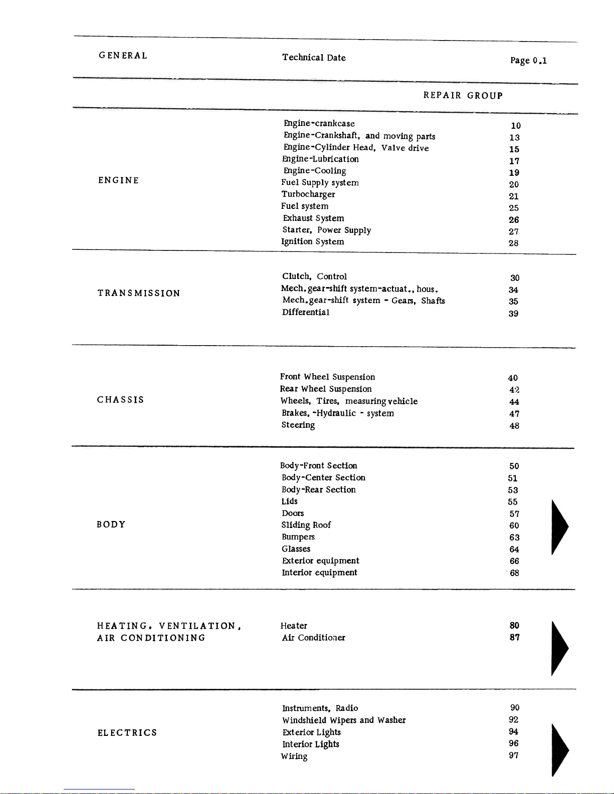
GENERAL
Technical Date
Page 0.1
REPAIR GROUP
10
13
15
17
19
20
21
25
26
27
28
ENGINE
Engine-crankcase
Engine-Crankshaft, and moving parts
Engine-Cylinder Head, Valve drive
Engine-Lubrication
Engine -Cooling
Fuel Supply system
Turbocharger
Fuel system
Exhaust System
Starter, Power Supply
Ignition System
30
34
35
39
Clutch, Control
Mech. gear-shift system -actuat., hous.
Mech.gear-shift system -Gears, Shafts
Differential
TRAN S MISSION
40
4":>'
44
47
48
CHASSIS
Front Wheel Suspension
Rear Wheel Suspension
Wheels, Tires, measuring vehicle
Brakes, -Hydraulic -system
Steering
50
51
53
55
57
60
63
64
66
68
BODY
Body-Front Section
Body-Center Section
Body-Rear Section
Lids
Doors
Sliding Roof
Bumpers
Glasses
Exterior equipment
Interior equipment
HEATING. VENTILATION.
AIR CONDITIONING
Heater
Air Conditioaer
80
87
90
92
94
96
97
Instruments, Radio
Windshield Wipers and Washer
Exterior Lights
Interior Lights
Wiring
ELECTRICS
911 turbo
Alphabetical Index
Volume II
Page
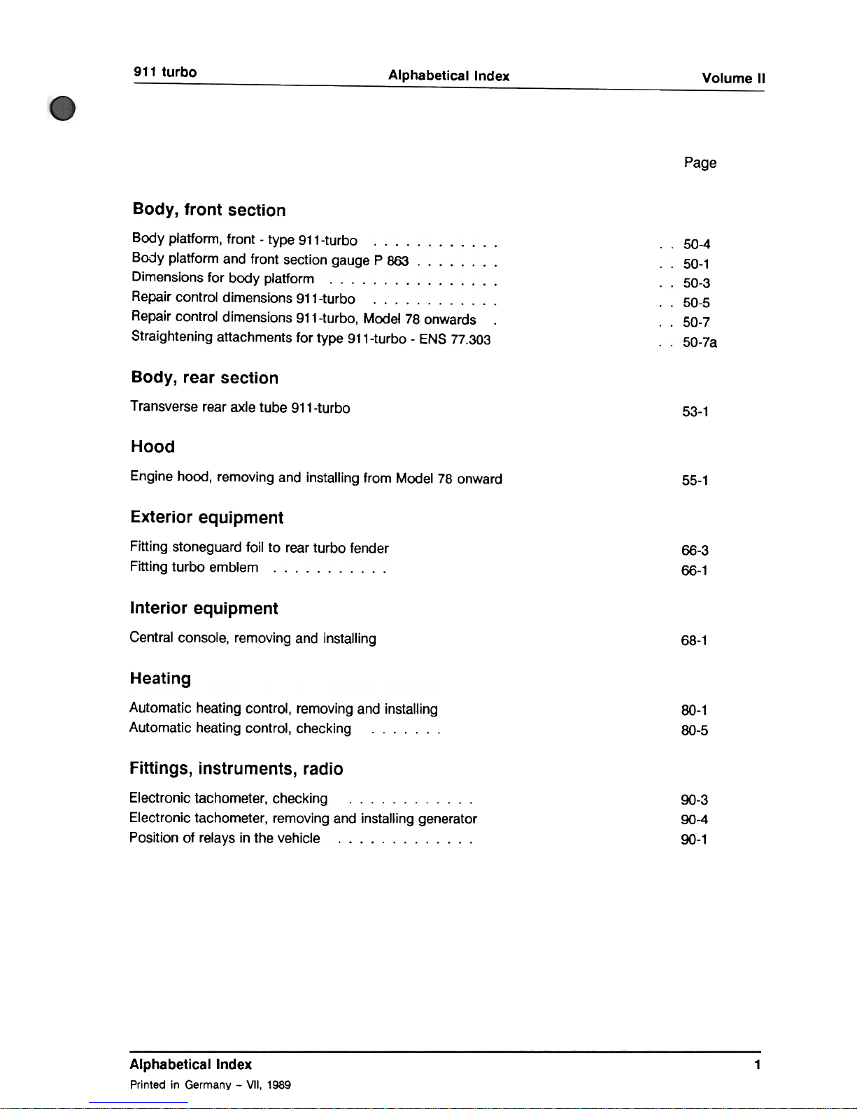
Body, front section
..50-4
..50-1
..50-3
..50-5
..50-7
..50-7a
Body platform, front -type 911-turbo Body platform and front section gauge P 863 Dimensions for body platform. Repair control dimensions 911-turbo Repair control dimensions 911-turbo, Model 78 onwards
Straightening attachments for type 911-turbo -ENS 77.303
Body, rear section
Transverse rear axle tube 911-turbo
53-1
Hood
Engine hood, removing and installing from Model 78 onward
55-1
Exterior equipment
66-3
66-1
Fitting stoneguard foil to rear turbo fender
Fitting turbo emblem.
Interior equipment
Central console, removing and installing
68-1
Heating
Automatic heating control, removing and installing
Automatic heating control, checking.
00-1
00-5
Fittings, instruments, radio
9()-3
9()-4
9()~1
Electronic tachometer, checking. Electronic tachometer, removing and installing generator
Position of relays in the vehicle.
Alphabetical Index
Printed in Germany -VII, 1989
1

Volume II
Alphabetical Index
911 turbo
Page
97-1
97-13
97-19
97-17
97-29
97-25
97-23
97-7
97-31
97-11
97-9
97-27
97-5
97-61
97-79
97-115
97-153
97-197
Wiring
Current-flow diagram -911 turbo, Model 76 Current-flow diagram -911 turbo, Model 77 Current-flow diagram -911 turbo, Model 78 Additional current-flow diagram -exhaust temperature monitoring -type 911 turbo
Additional current-flow diagram -automatic heating control. Additional current-flow diagram -electric windows. Additional current-flow diagram -rear window wiper. Additional current-flow diagram -refrigerant system with front condenser. ...
Additional current-flow diagram -air-conditioning system. Additional current-flow diagram -engine compartment light. Additional current-flow diagram -fog lamp. Additional current-flow diagram -headlight cleaning system. Additional current-flow diagram -intermittent wiper c!rcuit, Model 76 Additional circuit diagram -alarm system, Model 85 Circuit diagram, Model 86 Circuitdiagram,ModeI87 Circuitdiagram,ModeI88 Circuitdiagram,ModeI89
Alphabetical Index
Printed in Germany -VII, 1989
2
Body -Front Section
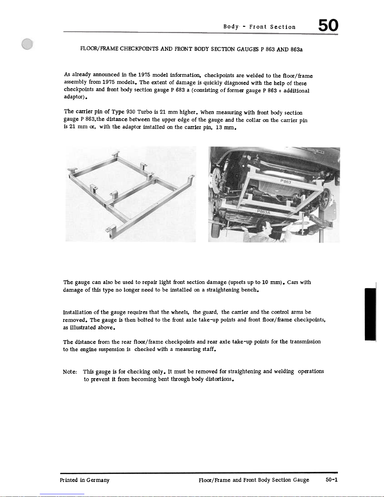
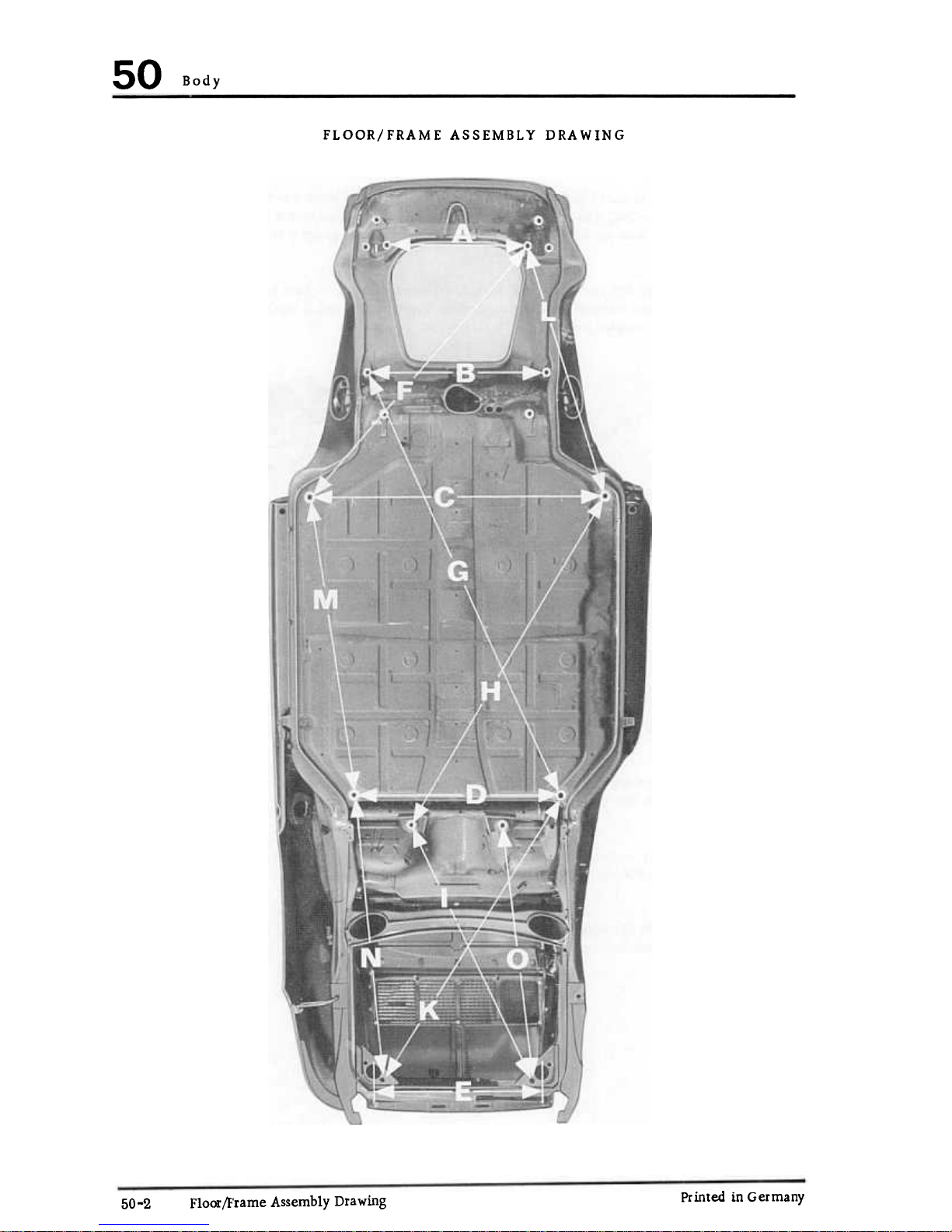
FLOOR/FRAME CHECKPOINTS AND FRONT BODY SECnON GAUGES P 863 AND 863a
As already announced in the 1975 model information, checkpoints are welded to the floor/frame
assembly from 1975 models. The extent of damage is quickly diagnosed with the help of these
checkpoints and front body section gauge P 683 a (consisting of former gauge P 863 + additional
adaptor) .
The carrier pin of Type 930 Turbo is 21 mm higher. When measuring with front body section
gauge P 863,the distance between the upper edge of the gauge and the collar on the carrier pin
is 21 mm or, with the adaptor installed on the carrier pin, 13 rom.
The gauge can also be used to repair light front section damage (upsets up to 10 mm). Cars with
damage of this type no longer need to be installed on a straightening bench.
Installation of the gauge requires that the wheels, the guard, the carrier and the control arms be
removed. The gauge is then bolted to the front axle take-up points and front floor/frame checkpoints,
as illustrated above.
The distance from the rear floor/frame checkpoints and rear axle take-up points for the transmission
to the engine suspension is checked with a measuring staff.
This gauge is for checking only. It must be removed for straightening and welding operations
to prevent it from becoming bent through body distortions.
Note:
Printed in Germany
50-1
Floor/Frame and Front Body Section Gauge
50
Body
FLOOR/FRAME ASSEMBLY DRAWING
Printed in Germany
Floor/F'rame Assembly Drawing
50-2
Body
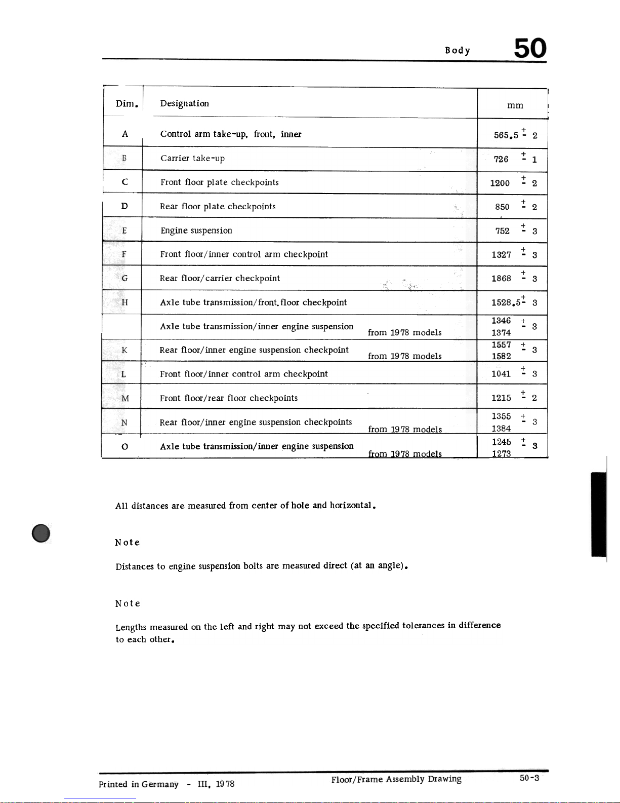
Dim.
Designation
mm
+
565.5 -2
A
Control arm take-up, front, inner
!
1
Carrier take-up
726
! 2
Front floor plate checkpoints
c
1200
! 2
D
Rear floor plate checkpoints
850
! 3
E
Engine suspension
752
!. 3
F Front floor/inner control arm checkpoint
1327
!. 3
Rear floor/ carrier checkpoint
1868
G
+
1528.5- 3
H Axle tube transmission/front. floor checkpoint
1346 "!. 3
1374
Axle tube transmission/inner engine suspension
from 1978 models
1557 :!: 3
1582
Rear floor/inner engine suspension checkpointK
from 1978 models
"to 3
1041
L
Front floor/inner control arm checkpoint
+
1215 -2
Front floor/rear floor checkpoints
M
1355 ! 3
13~4_-
Rear floor/inner engine suspension checkpoints
N
U91ILlll8models
0 Axle tube transmission/inner engine suspension 1245 :: 3
1273
All distances are measured from center of hole and horizontal.
Note
Distances to engine suspension bolts are measured direct (at an angle).
Note
Lengths measured on the left and right may not exceed the specified tolerances in difference
to each other.
Body -Front
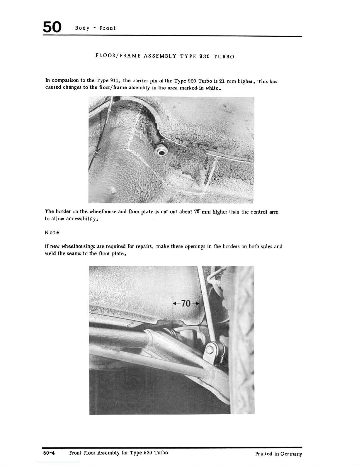
FLOOR/FRAME ASSEMBLY TYPE 930 TURBO
In comparison to the Type 911, the carrier pin <i the Type 930 Turbo is 21 mm higher. This has
caused changes to the floor/frame assembly in the area marked in white.
The border on the wheelhouse and floor plate is cut out about 70'mm higher than the control arm
to allow accessibility.
Note
If new wheel housings are required for repairs. make these openings in the borders on both sides and
weld the seams to the floor plate.
Front Floor Assembly for Type 930 Turbo
50-4
Printed in Germany
Body
')"'
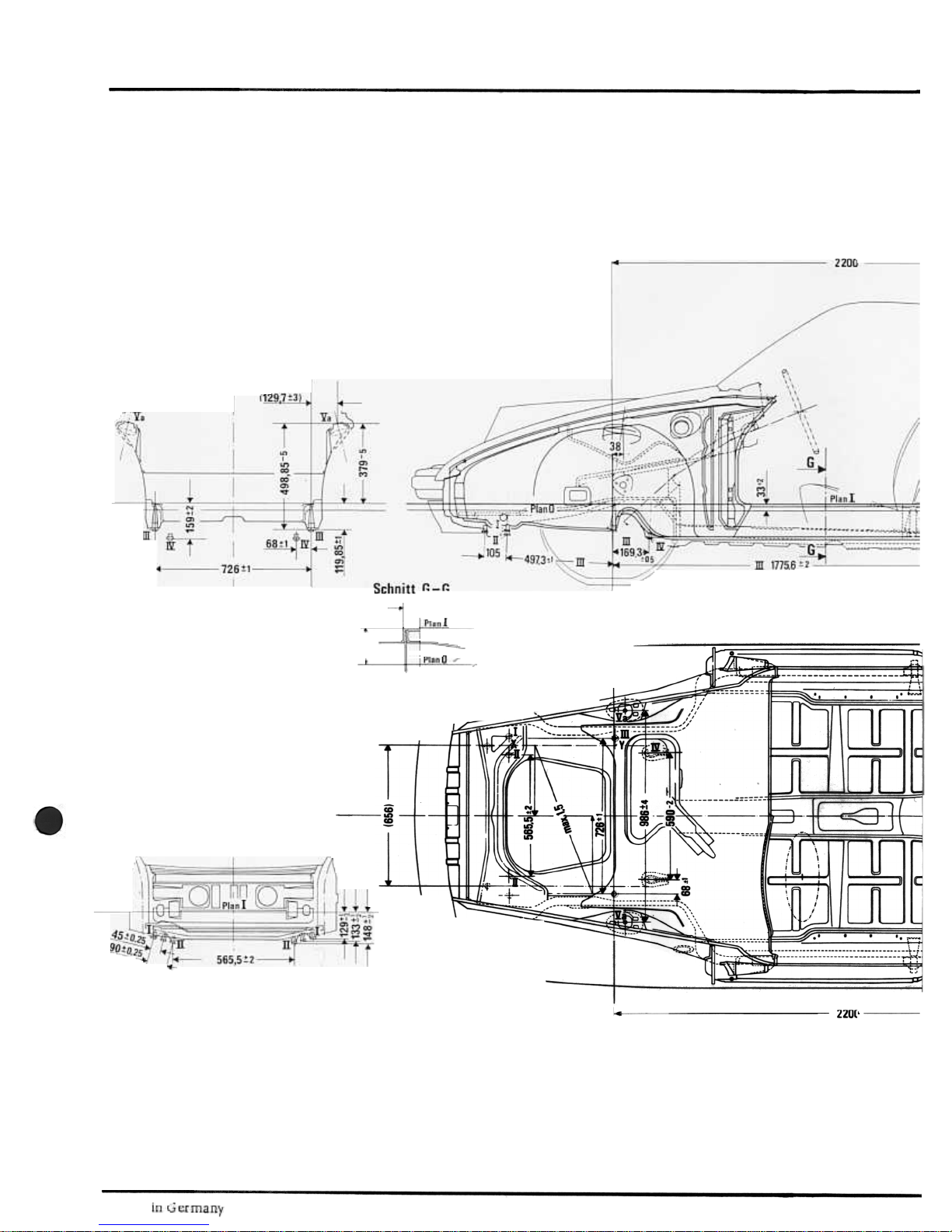
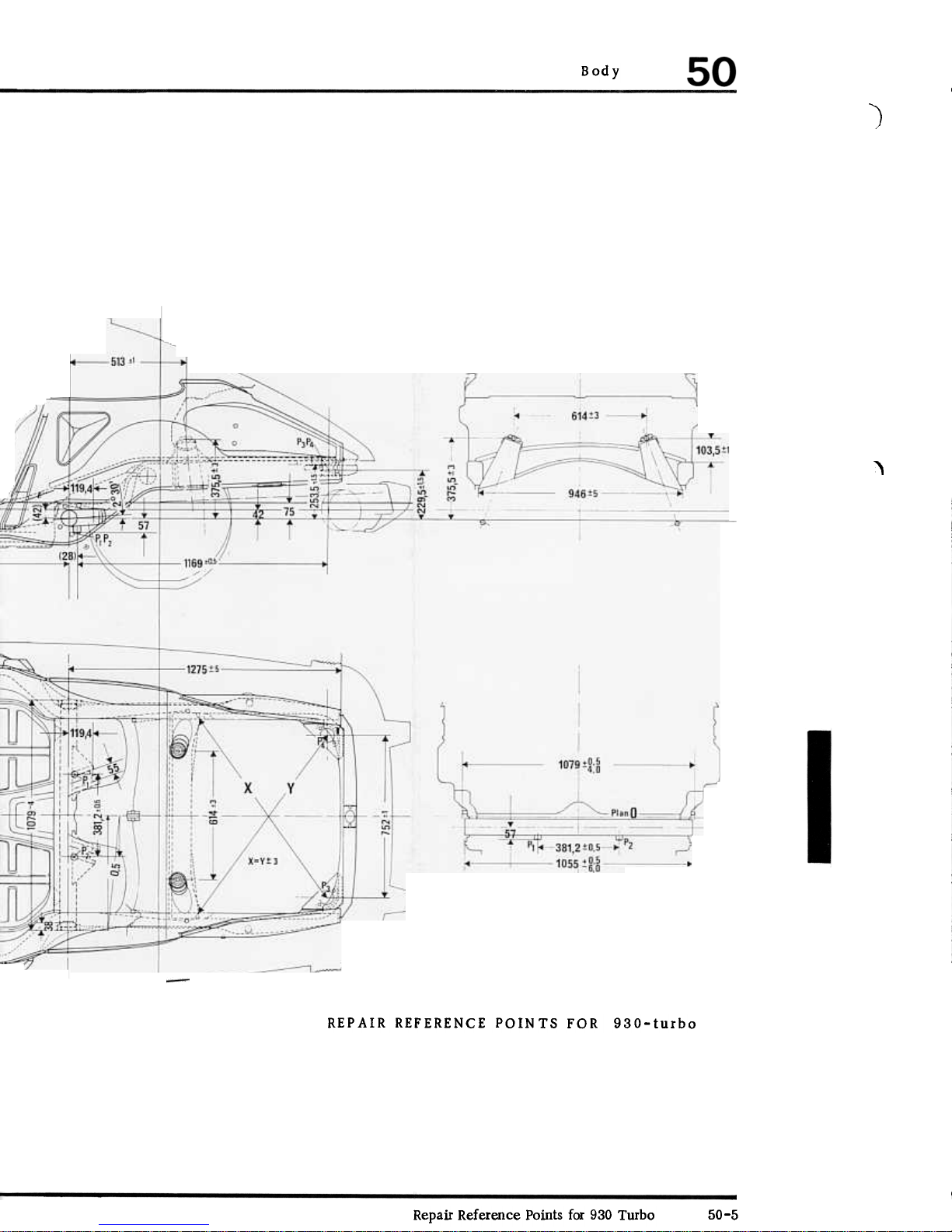
REPAIR REFERENCE POINTS FOR 930-turbo
Repair Reference Points for 930 Turbo 50-5
 Loading...