

Porsche 2012 911 GT3 CUP, 911 GT3 Cup 2011 Technical Manual

Technical Manual
2012 Model

Preface
This technical information will give you the possibility to reference data,
adjustment values and working procedures and make the maintenance
and repair work on the vehicle easier.
We wish you every success with your GT3 Cup
Dr. Ing. h.c. F. Porsche
Aktiengesellschaft
Vertrieb Sonder- und Rennfahrzeuge

Race car 911 GT3 Cup Model 2012
This car is specifically designed for participation in one-make cup
competitions.
For obvious reasons, measurements referring to bodywork dimensions
of the production cars cannot be used as reference.
Porsche accepts no guarantee that the vehicle conforms to the
regulations.
The car can not be registered for road use and does not comply with
German road traffic regulations.
Illustrations, descriptions and schematic drawings serve exclusively as
presentation for the text. Porsche Motorsport accepts no liability for the
completeness and conformity of the contents of this brochure with
respect to the legality of the current regulations.

1
Contents
1. CONTACTS 4
2. GENERAL TECHNICAL DATA 5
2.1. Dimensions 5
2.2. Weight 5
3. ENGINE 6
3.1. Engine technical data 6
3.2. Engine power and torque curves 7
3.3. Engine lubrication 8
3.4. Engine cooling system 12
3.5. Induction system 18
3.6. Throttle butterfly 18
3.7. Working on the engine 23
3.8. Engine component tightening torques 36
3.9. Engine mileage 37
4. FUEL AND EXHAUST SYSTEM 38
4.1. Fuel system 38
4.2. Fuel cell 39
4.3. Exhaust system 42
5. GEARBOX 46
5.1. Technical data gearbox 46
Gearbox layout 47
5.2. 47
5.3. Modifications 2012 model 48
5.4. Gearbox lubrication 49
5.5. Ratio chart 49
5.6. Gear recognition 50

2
5.7. Changing gear 51
5.8. Differential 53
5.9. Clutch 54
5.10. Working on the gearbox 57
5.11. Tightening torques gearbox 79
5.12. Gearbox mileage 79
6. SUSPENSION 80
6.1. Front suspension 80
6.2. Rear suspension 84
6.3. Basic wheel alignment 87
6.4. Wheel alignment procedure 88
6.5. Working on the suspension 95
6.6. Tightening torques suspension 96
6.7. Sachs damper service information 106
7. WHEELS 108
8. BRAKE SYSTEM 110
8.1. Technical data brake system (steel) 110
8.2. Technical data brake system (PCCB) 110
8.3. Brake force distribution (brake balance) 111
8.4. Brake caliper 118
8.5. PCCB brake disk information 118
8.6. Tightening torques brake system 119
9. CHASSIS 120
9.1. Interior 120
9.2. Exterior 120
9.3. Rear wing 121
9.4. Fire extinguisher system 122

3
9.5. Air-jack system 124
10. ELECTRIC 126
10.1. Alternator 126
10.2. Battery 126
10.3. Steering wheel 126
10.4. Centre console 128
10.5. Shift Light Module 129
10.6. MoTeC Dash 130
10.7. Car sensors 134
10.8. Engine Control Unit (ECU) 136
10.9. Relay- and fuse assignment 137
10.10. Fuse carrier 138
11. CAR MAINTENANCE 139
11.1. After approx. 200 km and/or first test 139
11.2. After every session 139
11.3. After every race weekend (sprint) 140
11.4. After 3 - 4 race weekends (sprint) 140
11.5. After 20 respectively 30 hours running time 140
11.6. After 50 hours running time 140
11.7. Operating fluids 141

4
1. Contacts
International One Make Cups Mr Michael Dreiser 0711 911 82684
Assistant Mrs Juliane Gründl 0711 911 82683
Technical support Mr Marcus Stolzenthaler 0711 911 82498
Fax: 0711 911 82920
Porsche Mobil 1 Supercup Mr Jonas Krauss 0711 911 84042
Assistant Mrs Jennifer Biela 0711 911 84096
Technical support Mr Steffen Höllwarth 0711 911 89922
Fax: 0711 911 82920
Porsche Carrera Cup Germany Mr Helmut Greiner 0711 911 84074
Assistant Mrs Andrea Hagenbach 0711 911 84041
Technical support Mr Stefan Rometsch 0711 911 84613
Fax: 0711 911 82920
Sport parts sales Mr Friedrich Weseler 0711 911 89854
Mr Karlheinz Kienle 0711 911 82923
Mr Klaus Lenzner 0711 911 82423
Mr Christian Müller 0711 911 89175
Mr Salvatore Scozzaro 0711 911 83738
Mr Emanuel Donno 0711 911 82687
Fax: 0711 911 82808

5
2. General technical data
Engine type M 97/78
Gearbox type G 97/63
Numbers of gears sequential 6
2.1. Dimensions
Length (w/o spoiler edge) [mm] 4423
Width across front axle [mm] 1787
Width across rear axle [mm] 1859
Wheelbase [mm] 2353
2.2. Weight
Dry weight [kg] appr. 1200
With steel brakes, without front exhaust silencer

6
3. Engine
The engine is based on the power unit fitted to the road approved
911 GT3 and is specially modified for motorsport purposes.
The engine is fitted with a dry sump lubrication system; the oil tank is
mounted directly on the engine. The engine oil is cooled by an oil-water
heat-exchanger integrated in the cooling system.
3.1. Engine technical data
Engine type M97/78
Design
Six-cylinder boxer
Cylinders
6
Bore
[mm] 102.7
Stroke
[mm] 76.4
Cubic capacity
[cm³] 3797
Compression ratio
approx. 12 : 1
Maximum revs
[rpm] 8,500
Inlet valve diameter
[mm] 41
Inlet valve lift
[mm] 12.0
Point of maximum
inlet valve lift
[°] 105 after TDC
Exhaust valve
diameter
[mm] 35.5
Exhaust valve lift
[mm] 12.0
Point of maximum
exhaust valve lift
[°] 110 before TDC
Cooling media
Water cooled
Lubrication
Dry sump lubrication
Oil-water heat-exchanger
7
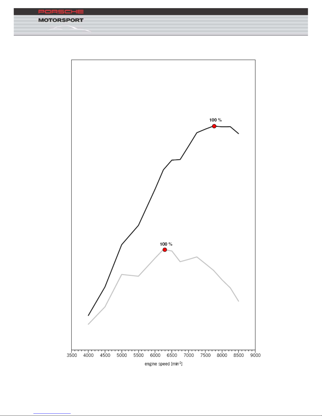
3.2. Engine power and torque curves

8
3.3. Engine lubrication
The 911 GT3 is equipped with a dry sump lubrication system. The oil tank
is mounted to the engine.
The engine oil is cooled by an oil-water heat-exchanger mounted on the
engine.
3.3.1. Engine oil
Mobil 1 0W - 40
Mobil 1 5W - 40
9
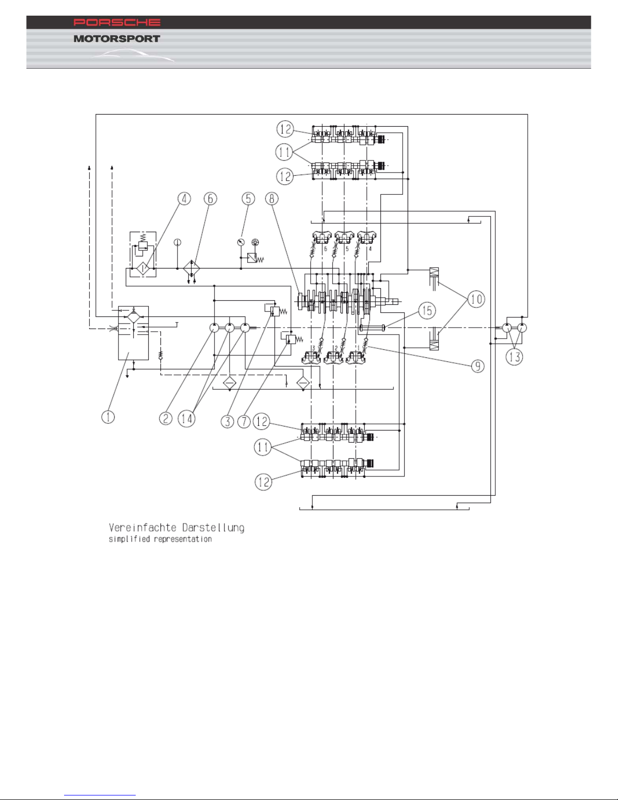
3.3.2. Engine oil system
1 – Oil tank
9 – Piston cooling
2 – Pressure pump 10 – Timing chain tensioner
3 – Safety valve 11 – Camshaft
4 – Oil filter 12 – Hydraulic valve lifter
5 – Pressure sensor 13 – Camshaft housing scavenge pump
6 – Oil-water heat-exchanger 14 – Crankcase scavenge pump
7 – Pressure relief valve 15 – Balance shaft
8 – Crankshaft

10
3.3.3. Checking the oil level
The engine oil temperature must be over 80°C and the engine running at
idle speed (approx 2,000 rpm) to measure the oil level correctly. The oil
level must be between the two marks on the dip-stick. The distance
between the two marks corresponds to 1 litre of engine oil.
An e
xcessively high oil level can lead to oil entering the induction
tract.
If engine oil is added it should be noted that this oil only flows slowly into
the oil tank through the dip-stick guide sleeve. Therefore the oil level
should only be measured again after waiting for a few minutes.
The engine oil level must be checked regularly and corrected
when necessary especially when the engine is new. Oil pressure
signal drop outs in the MoTeC data logging are a clear indication
for low oil level. Therefore the oil pressure must be carefully and
regularly monitored. (e.g. with MoTeC). The MoTeC oil pressure
alarm is active if the oil pressure falls below 2.5 bar for at least
one second at an engine speed of 2,500 rpm or greater (for a
minimum of two seconds).
3.3.4. Filling capacities
New engine: 11.0 l
With oil filter change: 8.3 l
Without oil-filter change 8.1 l

11
3.3.5. Digital oil level display
An optional oil level display is available (997.641.139.9A):
The car wiring loom is already prepared for use of this display. The
connector for the display is located in the area of the rear side-window on
right-hand side of the car.
In addition, the oil level sensor 996.606.140.00 is necessary for
displaying the oil level. The sensor is plugged in the oil tank.
Attention: Do not fill above 90 %
12
3.4. Engine cooling system
The GT3 Cup cooling system is a standard cooling system optimised for
use in a race car.
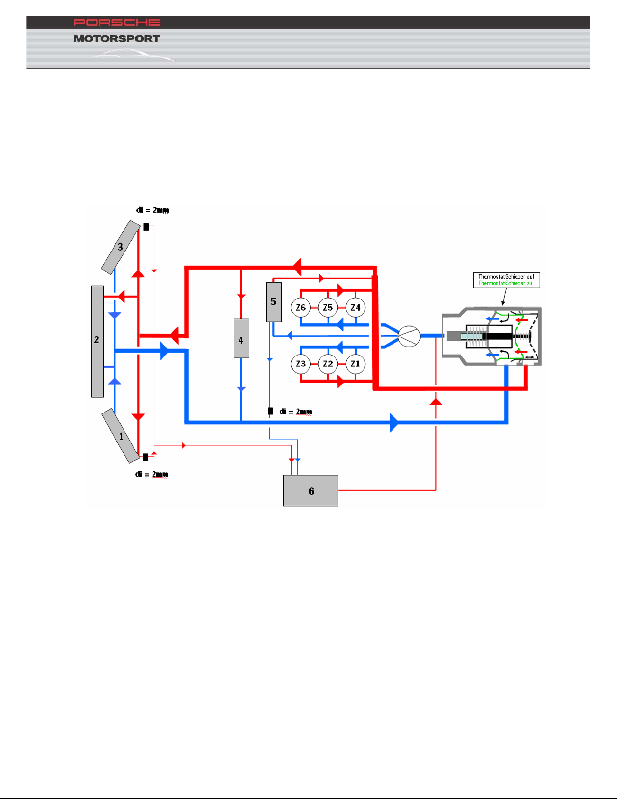
3.4.1. Scheme drawing
1 – Left-hand side cooler 4 – Gearbox heat-exchanger
2 – Centre cooler 5 – Engine heat-exchanger
3 – Right-hand side cooler 6 – Cooling water expansion tank
di – Bleed throttle
3.4.2. Thermostat
The thermostat fitted starts to open when the water temperature exceeds
60°C. The thermostat is completely open from 72°C.

13
3.4.3. Cooling fluid
The cooling system if filled with 11 litres of water and 11 litres of anti-
freeze when delivered. The coolant remains fluid to temperatures of -30°C
in delivery specification with this water/anti-freeze ratio.
For all race events Porsche Motorsport recommends that the factory filled
engine coolant is replaced by 20 litres of water and 2 litres of anti-
corrosion additive (part number. 997.106.907.90), which protects the
water galleries and other cooling system parts from corrosion, reduces
cavitation, lubricates the water pump and increases the boiling point of
the cooling water.
For Cup races supporting Formula 1 events the coolant must be
changes as described below: Approx 20 litres water plus minimum
2 litres anti-corrosion additive part number 997.106.907.90.
3.4.3.1. Capacity
Approx 22 litre
s
14
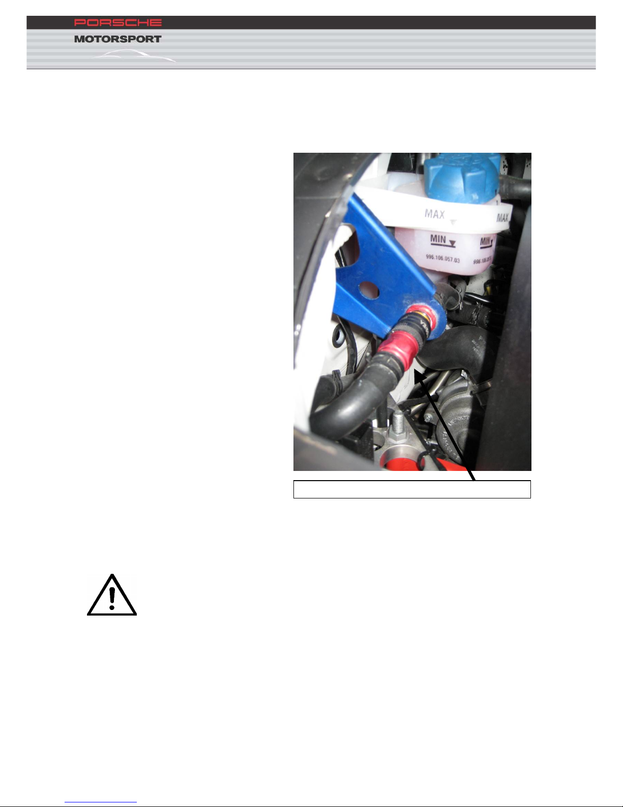
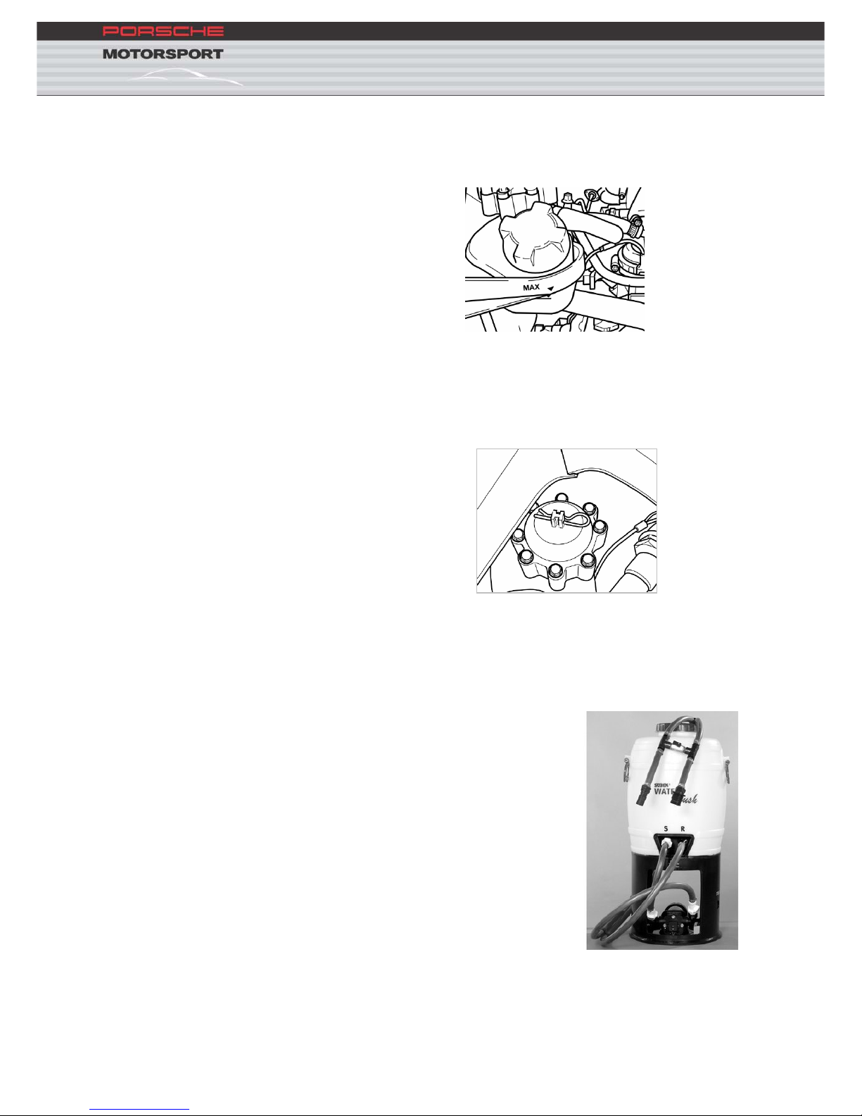
3.4.4. Filling the cooling system
A quick-release coupling is integrated in the engine bay in the area of the
expansion tank. The water system can be filled and bled quickly and
safely via this coupling – after an engine change for example.
When the water system has reached its operating temperature,
the expansion tank cap should under no circumstances be opened
and the pressure released. Since the operating temperature has
already been achieved the water pressure cannot be built up
again. This system pressure is necessary to increase the coolant
boiling point.
Q
uick release coupling
15
Valves in the expansion tank allow the exhaust of steam at a pressure of
1.4 bar, and the release of water at a pressure of 1.8 – 2.0 bar.
The bleed valve in the standard production car improves the initial
reaction from the heating system; the valve remains open in the race car
system allowing the system to be bled continuously.
A special filling system available from Sobek should be used to fill the
water system. The filling system consists of an electric pump that pumps
water from a tank into the system.
Bernd Sobek – Mattern
Fliederstr. 10
D – 69517 Gorxheimertal
Tel +49 (0) 6201 2051
Fax +49 (0) 6201 21834
www.sobek-motorsporttechnik.eu
16
Filling the system should be carried out as follows:
Disconnect the quick release fittings in the engine bay and
connect the corresponding fittings with those of the filling system
Switch on the pump, the system will be filled
The device must run for ten minutes to guarantee that the system
is correctly filled and bled
Warm-up the engine (80°C) and, if required, fill the reservoir
to the maximum level with the filling device still attached
The e
xpansion tank cap must be closed throughout the
entire procedure
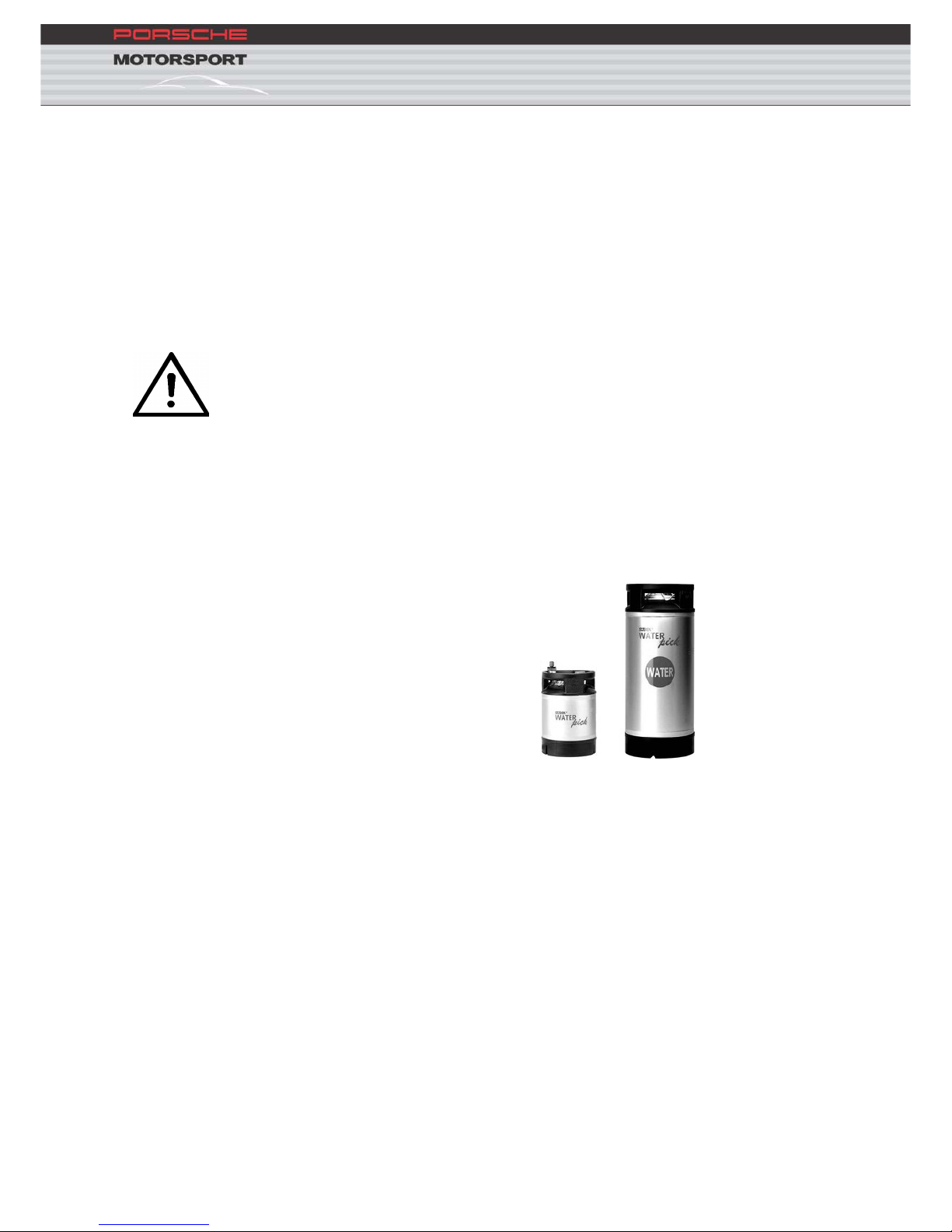
3.4.4.1. Filling the cooling system with engine at
normal operating temperature:
A special filling system to fill the engine water system when the engine is
at normal operating temperature is also available from Sobek. This
appliance consists of a fluid reservoir with a coupling. The reservoir is
charged with a pressure of 2.5 – 3.0 bar.
The system filling procedure must be carried out as follows:
Disconn
ect the quick release fitting in the engine bay and connect
the filling system coupling to the corresponding end of the quick-
release fitting.
The system is filled via the expansion tank.
17
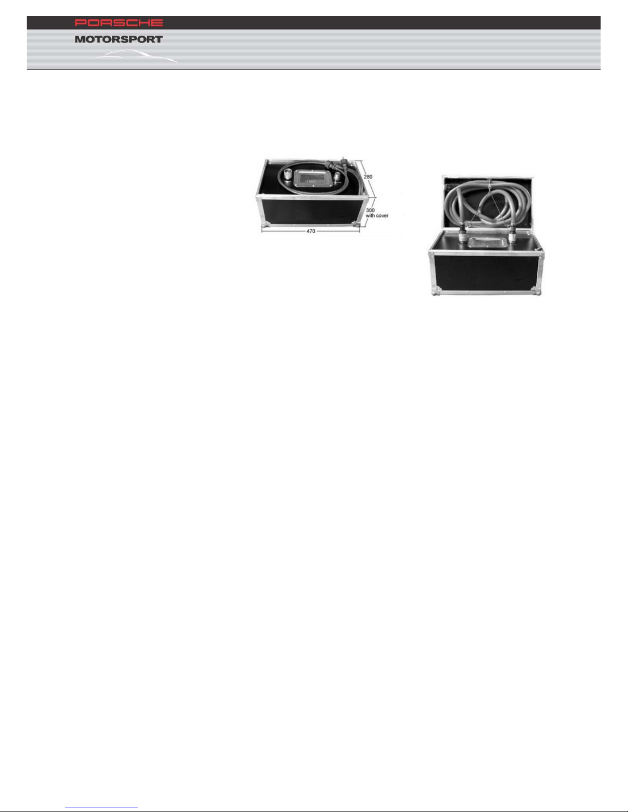
3.4.4.2. Filling the cooling system with pre-heated water
A special filling system to fill the engine water system when the engine is
at normal operating temperature is also available from Sobek.
18
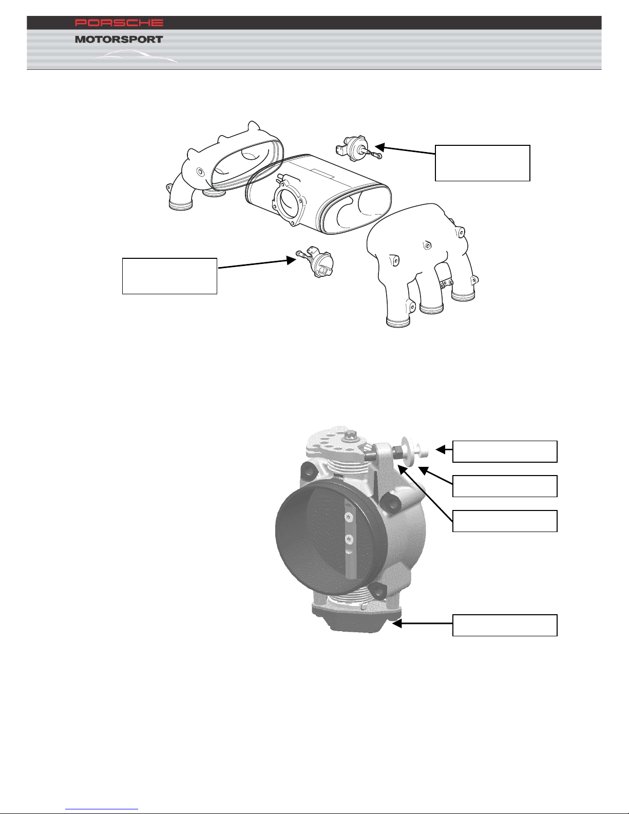
3.5. Induction system
V
acuum actuator
Reso 1 (su)
V
acuum actuator
Reso 2 (su2)
Four-stag
e resonance induction system
Activated by vacuum actuator resonance valves (x2)
3.6. Throttle butterfly
1.) Adjuster screw
2.) Lock nu
t
3.) Threaded bush
4.) Potentiometer
Mechan
ical single throttle butterfly without by-pass
Idle speed set via adjuster screw
19
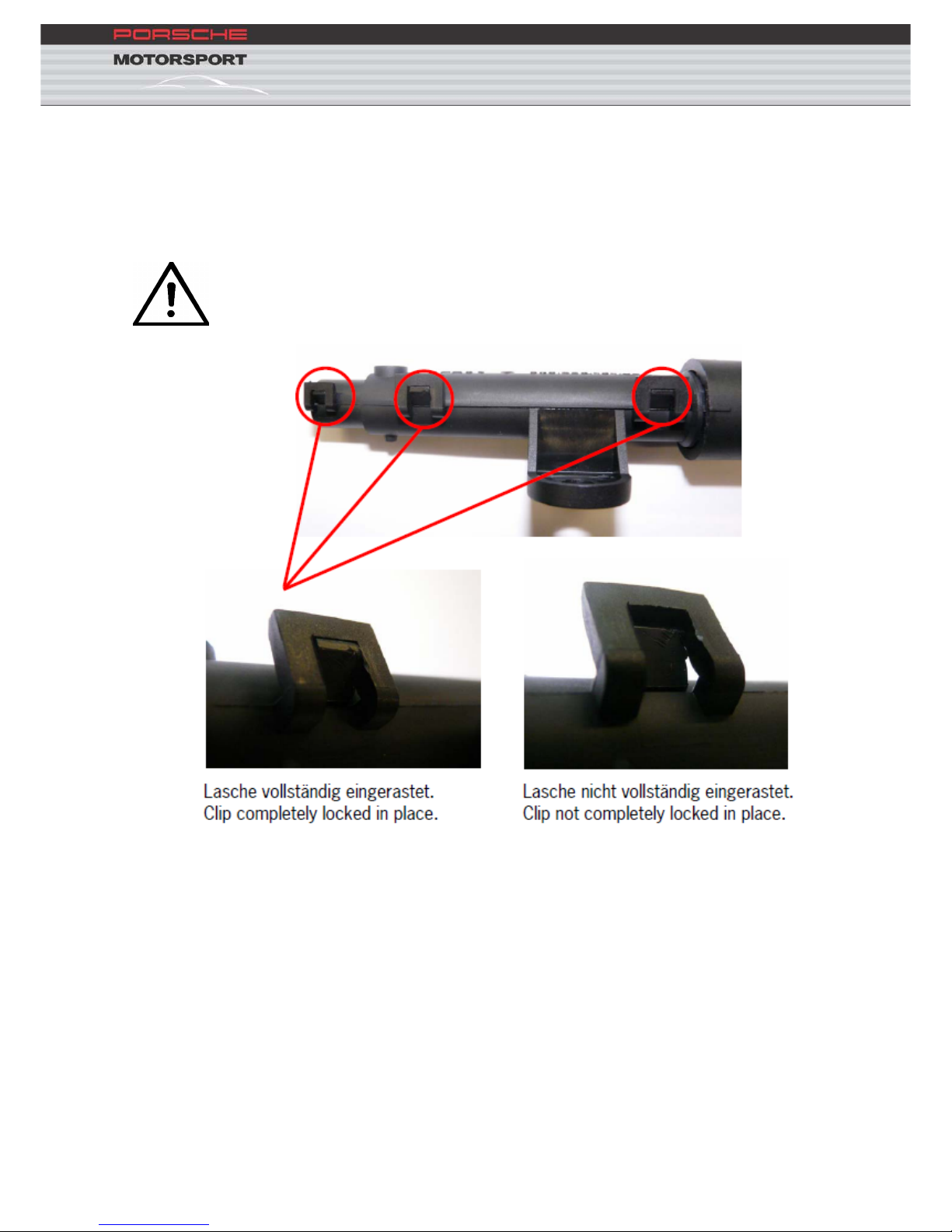
3.6.1. Throttle cable
Compensation of the throttle-cable length is made by the spring fitted in
the connecting piece. To achieve this the spring is tensioned and/or un-
tensioned by rotating the connection piece.
We point out that it is imperative to ensure the complete locking of
all 3 clips of the housing of the connecting piece.
20
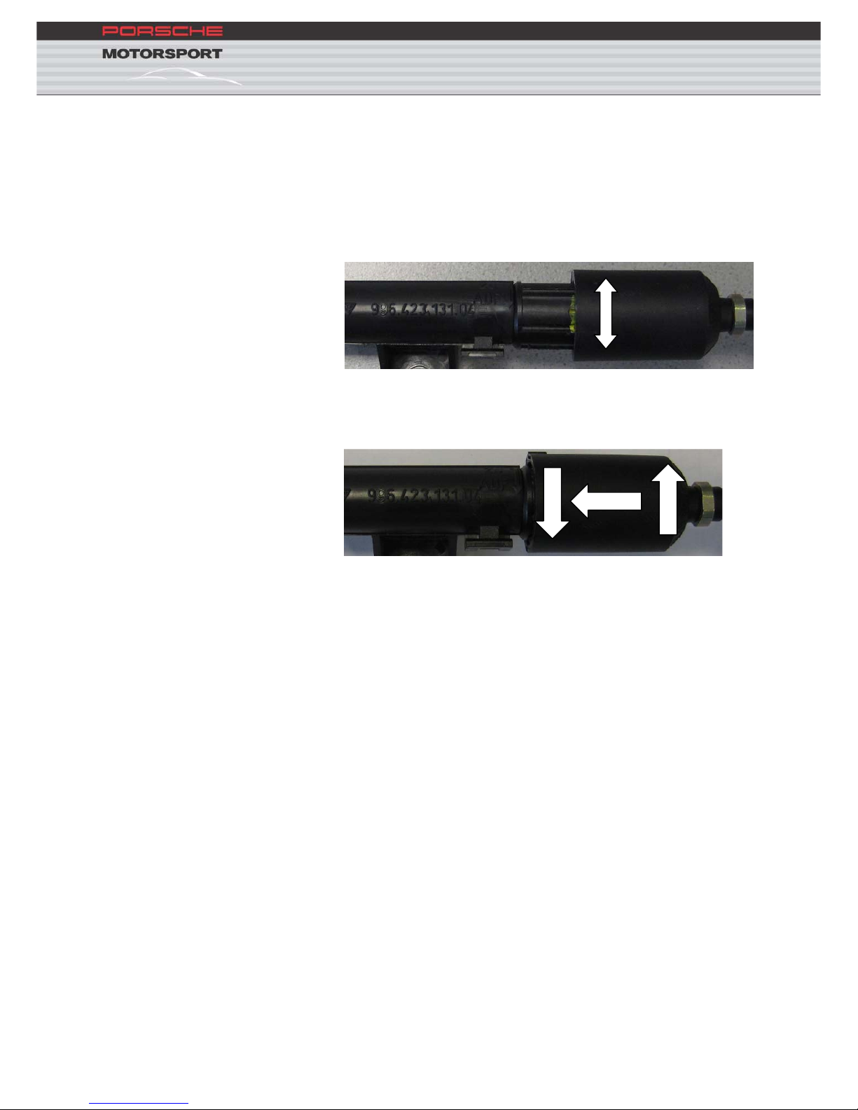
3.6.1.1. Tension-free setting of the throttle cable
Be
fore calibrating the throttle-butterfly potentiometer the throttle cable
must be set “tension-free”:
1. Rotate the throttle cable in the direction “auf” on the connecting
part behind the driver seat
close
open
2. Press t
he two halves of the connecting part together
3. Rotate the throttle cable in the direction “zu”
1 3
2
The
throttle cable has play in this position. Tasks such as throttle butterfly
reset can now be carried out.
21
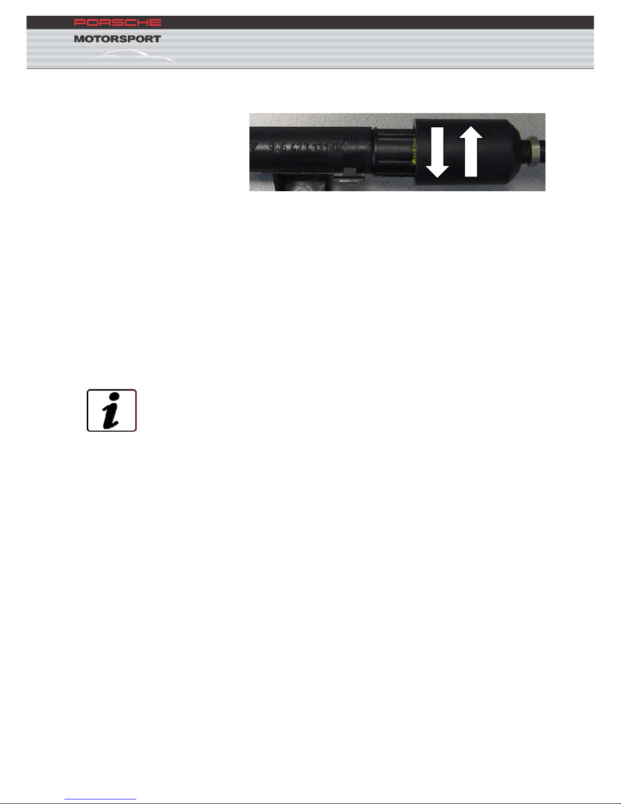
3.6.1.2. Play compensation
To remove throttle cable follow the procedure described below:
2
1
1. The
throttle cable is tensioned automatically by the length
compensation spring
2. To finish, rotate the connecting part in the direction “close” till the
marking lugs on both parts of the connecting part are aligned
The throttle cable is tensioned automatically by the length compensation
spring
3.6.2. Throttle butterfly potentiometer calibration
The throttle butterfly potentiometer must always be recalibrated if:
ECU was changed or reprogrammed
Engi
ne was changed
Throttle butterfly potentiometer was changed
Implausible throttle butterfly position values are displayed
The following steps must be taken to calibrate the potentiometer:
1. Adjust the throttle cable so it is tension free (see
3.6.1.1)
2. Disconn
ect the throttle cable from the cam-disc
3. Loosen the idle adjustment screw 1.)
4. The cam-disc must now rest on the threaded bush 3.),
the throttle butterfly is now completely closed.
Calibration of the throttle butterfly is made in this
position (reset the throttle butterfly angle to 0°)
5. This calibration is made via Bosch Modas a.) or the
MoTeC Dash b.)
22
a.) In Modas on the ‘Throttle’ page (in Engine F1) activate
the button ‘Set Throttle’
throttle angle wdkba_w shows 0°
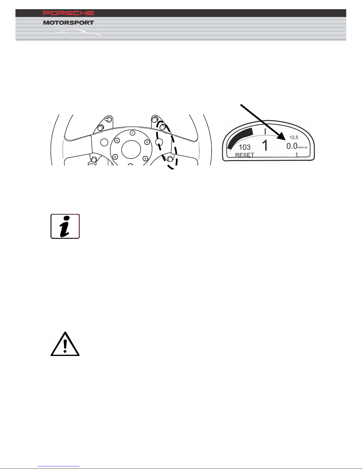
b.) Switch to Warmup mode, press and hold the ‘Display’ and
‘Alarm’ buttons for approx. 3 seconds till the ‘Reset’ appears
in the display and THR_BO goes to 0°
HIGH
BEAM
FLASHER
WIPER
DISPLAY
SPEED
ALARM
6. Screw t
he idle adjustment screw 1.) into the threaded
bush 3.) till a throttle value of appr. 6.5° (THR_BO in
Dash, wdkba_w in Modas) is displayed
7. The throttle value must NOT exceed 9° at idle (THR_BO
in Dash, wdkba_w in Modas)
8. Lock adjus
tment screw 1.)
9. Reconnect throttle cable to cam-disc
10. Tension the throttle cable (see 3.6.1.23.6.1)
3.6.3. Full throttle adjustment
Adjust the throttle pedal stop-screw so that full throttle equals 80° +/- 2°
(THR_BO in Dash, wdkba_w in Modas)
Attention: Only the adjustment screw under the throttle pedal
should be used to set full throttle. It is essential at full throttle, i.e.
when the throttle pedal is touching the stop, that there is sufficient
play in the throttle cable on the engine and that the throttle cable
movement is limited by the adjuster screw and NOT by the cable.
If the full throttle value is too high it is possible that mechanical
damage or a sticking throttle can occur.

23
3.7. Working on the engine
3.7.1. Connecting-rod bolt mounting instructions
1. Thoroughly clean the mating faces, bolt threads and the tapped
bores
2. Smear the threads and bolt head mounting faces with engine oil
3. Initial tightening torque: 30 +/- 3 Nm
4. Final tightening torque: 62 +/- 2° torque angle
5. Resulting elongation: 0.200 +/- 0.015 mm
Attention: Always renew the connecting rod bolts after
disassembly.
The joint surface must NOT be damaged.
As the connecting rods have a coated surface care must be taken that no
visible damage occurs to the connecting rod surface when dismantling
and assembling the engine. The connecting rods must NOT be polished.
24
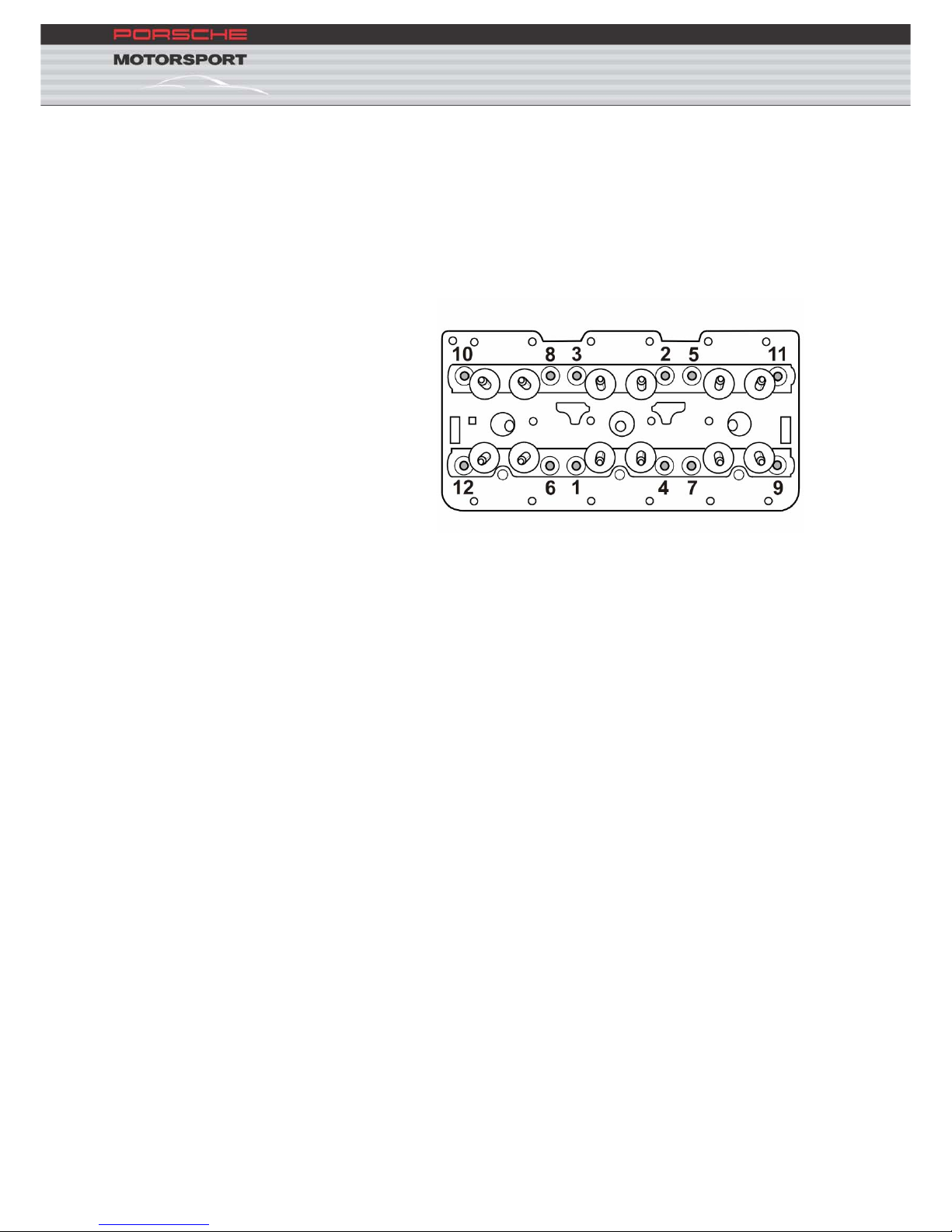
3.7.2. Mounting the cylinder head
The following procedure should be adhered to when mounting the cylinder
head:
1. Lightly oil the threads and mating faces
2. Tighten the bolts initially to 30 Nm in the following sequence,
and then wait 15 minutes
3. Completely loosen the bolts in the reverse sequence
4. Initially tighten the bolts to 20 Nm, before finally tightening to
120° torque angle
3.7.3. Flywheel tightening procedure
3.7.3.1. With used flywheel:
1. Loosen and remove the bolts
2. Replace with new bolts part number 930.102.206.00
3. Tighten the new bolts to 30 Nm (tighten sequence diagonally
opposed)
4. Retighten bolts to 30 Nm and an additional 45° torque angle
(tighten sequence diagonally opposed).
3.7.3.2. With new flywheel:
1. Bec
ause a new flywheel ‘settles’ it should be mounted initially
using used bolts as described above.
2. Replace with new bolts part number 930.102.206.00
3. Tighten the new bolts to 30 Nm (tighten sequence diagonally
opposed)
4. Retighten bolts to 30 Nm and an additional 45° torque angle
(tighten sequence diagonally opposed).

25
3.7.4. Set valve timing
3.7.4.1. Valve timing
Point o
f max inlet valve lift (EM) 105° after TDC
Point of max exhaust valve lift (AM) 110° before TDC
3.7.4.2. Special tools
Porsche Moto
rsport recommends use of the following special tools to
adjust and set the valve timing of the 911 GT3 Cup
Base plate cylinder 1: 996.721.549.90
Base plate cylinder 2: 996.721.550.90
Guide element EM/AM 110/110: 996.721.551.9A
Guide element EM/AM 105/115: 996.721.551.93
Degree wheel crankshaft: 996.450.131.00
Chain tensioner: 000.721.940.10
Setting jig TDC: 996.721.511.91
Retaining key timing chain sprocket: 996.721.513.90
26
3.7.5. Removing and fitting the crankshaft seal – pulley-side
3.7.5.1. Special tools
Porsche Moto
rsport recommends use of the following special tools to
remove and fit the pulley-side crankshaft seal:
Retaining key pulley: 000.721.973.20
Adapter retaining key pulley: 000.721.973.21
Press tool crankshaft seal: 000.721.216.40
Spacer for press tool: 000.721.979.71
Protective cap crankshaft: 000.721.979.70
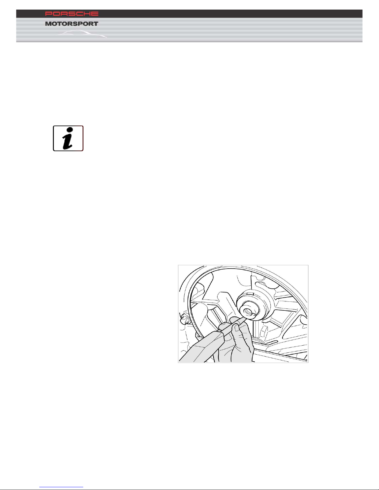
3.7.5.2. Removal
1. Remov
e the pulley from the crankshaft using the special tool
000.721.973.20 with the retaining key extension 000.721.873.20
2. Check the locating dowel on the pulley for damage and replace if
necessary
3. Centre-punch the steel ring in two points offset from one another by
180°
27
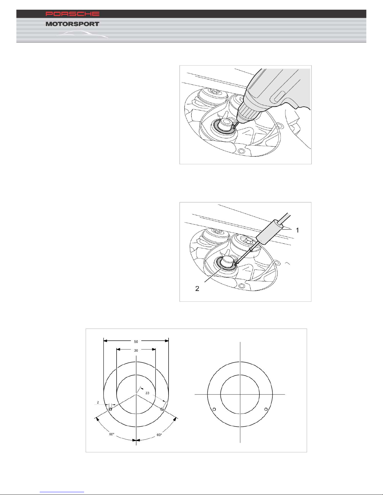
4. Drill two holes (Ø 2 mm) at the centre punched points
5. Screw the threaded-end of a commercially available slide hammer -1-
into the drilled holes. Carefully remove the seal -2- by swapping the slide
hammer alternatively between the drilled holes
6. Make a drill jig according to the following sketch (paper our thick
card). All dimensions in millimetre
 Loading...