

Porsche 928, 1987 928, 1986 928, 1988 928, 1989 928 Workshop Manual
...
Workshop Manual
l
DR. ING. h. c. F. PORSCHE Aktiengesellschaft

The Workshop Manual is only for the internal use of the Porsche Dealer Organization.
@ 1977 Dr. Ing. h.c. F. Porsche Aktiengesellschaft
Sales, D-7140 Ludwigsburg
All rights resewed - Printed in Germany XX, 1986
WKD 481 621
Print No. W 42-608-126-l

List of Repair Groups
General
Technical Data Paae 0.1
Repair Groups
Maintenance, Self-diagnosis
Group
03
Engine
Engine, Crankcase
Engine, Crankshaft, Pistons
Engine, Cylinder Head and Valve Drive
Engine, Lubrication
Engine, Cooling
Fuel Supply
Air Flow Controlled Fuel injection
Exhaust System/Emission Contrds
Starter, Power Supply, Cruise Control
Ignition System
10
13
15
17
19
20
24
26
27
28
Transmission
Chassis
Clutch, Controls
30
Torque Converter
32
Manual Transmission, Controls, Case
34
Manual Transmission, Gears, Shafts
35
Automatic Transmission, Controls, Case
37
Automatic Transmission, Gears, Valve Body
38
Differential, Transaxle System
39
Front Wheel Suspension
40
Rear Wheel Suspension, Axle Shaft
42
Wheels, Tires, Alignment
44
Antiblock System
45
Brakes, Mechanical
46
Brakes, Hydraulics
47
Steering
48
Body-Front Section
50
Body-Center Section
51
Body-Rear Section
53
Lids
55
Doors
57
Hardtop
61
Bumpers
63
Glasses, Window Control
64
Exterior Equipment
66
Interior Equipment
68
Seats
72
Seat Covers
74
Heating,
Heater
80
Ventilation,
Ventilation
85
Air Condition
Air Conditioner
87
Electrics
Instruments, Fuel Gauge, Alarm System
Radio
Windshield Wipers and Washer
Exterior Lights, Lamps, Switches
Interior Lights
Wiring
90
91
92
94
96
97
Printed in Germany - XX, 1997

928 Table of contents Volume III
a
General Data
Technical
data
Tightening torques
Torque Converter
Removing and installing torque convener
32-101
Removing and installing selector lever cover frame
37-101
Removing and installing selector lever cable
37-103
Adjusting selector lever cable
37-105
Removing and installing starter locking and backup light switch
37-107
Adjusting starter locking and backup light switch
37-109
Checking adjustment of selector lever cable and starter locking / backup light switch
37-l 11
Bowden cable for control pressure, removing and installing (service solution)
37-113
Bowden cable for control pressure, adjusting
37-115
Removing and installing transmission
37-l 17
Adjusting transmission suspension
37-123
Disassembling and assembling front convener housing
37-125
Disassembling and assembling front converter housing (‘87 models onward)
37-l 30
Removing and installing rear transmission case
37-131
Removing and installing rear transmission
37.135
Disassembling and assembling transmission
37-143
Transmission I Gears, Valve Body
Checking transmission operation
....................
Checking operation
...........................
Checking operation (87 models onward)
................
Troubleshooting.
............................
Removing and installing shift valve casing
...............
Disassembling and assembling shift valve housing
..........
Disassembling and assembling shift valve casing (‘87 models onward)
Removing and installing lower cover
..................
Disassembling and assembling lower cover
..............
Replacing ATF and filter
........................
Flushing ATF cooler and lines
.....................
Removing and installing governor
...................
Checking governor
...........................
Removing and installing vacuum modulator
..............
Removing and installing primary pump.
................
38-101
38-l 10
38-11 Oa
38-111
38-123
38-l 25
38-130a
38-131
38-133
38-137
38-141
38-143
38-145
38-147
38-149
Page
30-0101
30-0105
-
Table of contents
1
Prlnwd in Germany - XXXV, 1999

Volume III
Table of contents
929
Disassembling and assembling secondaty pump ...............
38-l 55
Disassembling and assembling gear assembly
................
38-l 57
Disassembling and assembling one-way clutch
................
38-163
Disassembling and assembling clutch K 1
..................
36-l 69
Disassembling and assembling clutch K 2
..................
38-177
Differential I Transaxle system
Removing and installing final drive ......................
Disassembling and assembling final drive
..................
Disassembling and assembling differential
..................
Disassembling and assembling bearing assembly
..............
Disassembling and assembling bearing assembly / Determining thickness of
shims for bearing assembly ..........................
Adjusting drive pinion and ring gear. .....................
Adjusting drive pinion and ring gear. .....................
Adjusting drive pinion and ring gear. .....................
Adjusting drive pinion and ring gear. .....................
Adjusting drive pinion and ring gear. .....................
Adjusting drive pinion and ring gear. .....................
Disassembling and assembling central tube
.................
Checking central tube .............................
PSD-Diagnosis I Troubleshooting .......................
39-l 01
39-107
39-113
39-l 19
39-123
39-125
39-127
39-128
39-130
39-133
39-135
39-137
39-139
D39-201
2
l
Table of contents
Printed In Genany - XXXV. 1999

928
General Data
30
a
4 - SPEED AUTOMATIC TRANSMISSION (UP TO '86 MODELS)
1 - Front converter casing
2 - Automatic transmission
a
3 - Final drive
Transmission Type
A 28.01
A 28.02
A 28.03
A 28.04
A 28.05
0 A 28.06
A 28.07
A 28.08
A 28.09
A 28.11
installed in
928 S, USA series / '83 and '84 models for Japan
928 S, Special option for Europe / rest of the
world,
'84 models
928 S, Special option (M 251) Europe / rest
of the world 3/84 onward (as 28.02, but
rear axle transmission ratio 13 : 33)
928 S, USA series / '85 models for Japan
928 S, Special option Europe / '85 models
rest of the world
928 S, Special option (M 251) Europe / '85 models
rest of the world (as A 28.05, but with
rear axle transmission ratio 13 : 33)
928 S, USA series / '86 models for Japan
928 S, Special option Europe / '86 models
rest of the world
928 S, Special option (M 251) Europe / '86 models
rest of the world (as A 28/08, but with
rear axle transmission ratio (13 : 33)
928 S, Australia series, special option (M 299)
for FGR, Switzerland, Austria, Sweden
('86 models)
0
Printed in
Germany-XX,1988
Technical Data
30 - 0101

30
Technical Data
General Data
920
0
4-speed automatic transmlsslon (‘87 models onward)
1 - Front converter casing
3 - Final drive
2 - Automatic transmission
Type
Key-number
Equipment Installed In model
a
A28.12 -
928 S 4 USNJap. 87188
A28.14 - 928 S 4 R.d.W. 87188
A28.16 -
928 S 4 worldwide 89/90/91
A28.18 -
928 GTS worldwide 92/93
30 - 0102
Technical Data
Printed in Germany - XXXI, 1993

928
General Data
30
a
Technical Data
Tmsmlsslon DeslgnatTon
1
A 28 02 12 1 6
E 05065
T
-r
[ - @zFc,985
1 = 5 - speed transmission
6 = Automatic
Transmission for 8 cylinder vehicles
Limited-slip differential 40 %
Country code
Transmission type
A 28 = four speed automatic
A 22 = three-speed automatic
G 28 = five-speed manual transmission
72227012
01
722316 02.~
A28.01
7222702501 72231602...=
A28.07
722 270 14
01
722 318 02...=
A 28.02/03
7222702601 72231602.~
A28.11
7222701701
72231602...=
A28.04
722 270 21
01 722 326 02...=
A 28.12/14
722 270 18
01 722 318 02...=
A 28.0.5/06
7222703201 72236003...=
A28.16
722 270 21
01
722 318 02...=
A 28.08/09
7222703401 72236003...=
A28.18
Technlcal Data
Printed in Germany - XXXI, 1993
30 - 0102a

30
General Data 928
Technical Data
Transmlssion
numbers
(12 dlglts)
A2814
T
Index for varlants
wlthln the assembly number
0 = no differential
1 = normal differential
2 = ZF limited slip differential
3 = proportional slip differential
Model year
Serlal
number
J = 1988
e.g. 00903
K = 1989
L = 1990
M = 1991
Note:
As from model ‘88. the gear box number will be readable from below, stamped on the rear stiffening
rib of the rear-axle housing
* As of MY ‘92, the model letter is omitted.
30 - 0102b Technical Data
a
Printed in Germany - XXXI. 1993

928
30
General data
Ratios
1st gear
2nd gear
3rd gear
4th gear
RDckw&tsgang
Final drive
Final drive ratio
(Stall speed)
Capacity, rear
axle final drive
Oil grade
Capacity, auto.
unl with
converter
A28.0 1/04/07/l 2
R8.02/03/05/06/08/09/11/14/16/18
Fully automatic 4-speed sun-an&planet transmis
368
2941
I,44
1 ,oo
5,14
Drive pinion without hypoid displacement
m
A 28/t 6
3,87
2,25
I,4
1 ,oo
5,59
15
: 33 i = 2,200 14 : 33
i = 2,357 (A 28.02/05/08)
13 : 33
i = 2,538 (A 28.03/06/09/
11/14/16’18)
A 28.01 =
A 28.02/03/05/06/08/09/l 1 =
2200...2600rpm 2200...2600rpm
up to MY ‘86 = approx. 2.7 I
from MY ‘87 to ‘90 = approx. 3.0 I
MY ‘91 = 2.3 I*
as of MY ‘92 = 1.9 I
Multigrade transmission oil 75 W 90 to MIL L 2105 B or
API classtication GL5
Total capacity = approx. 8.01 (‘87 models onward,
approx. 9.31). Capacity for fluid change with converter
= approx. 6.01 (‘87 models onward, approx. 7.31) ATF Dexron II D
* refer to Technical Information No. l/91 of 08.3.91
0
Technlcal Data 30 - 0103
Printed in Germany - XXXI. 1993
928
General 30
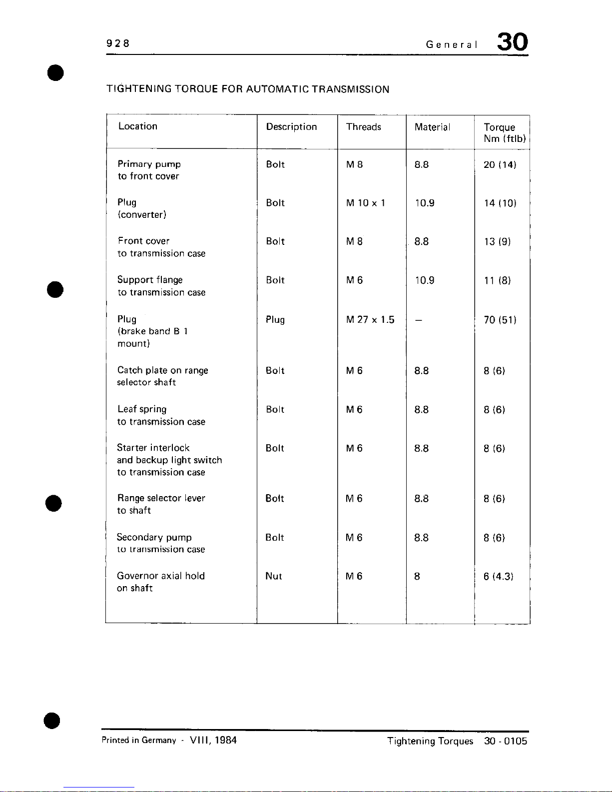
TIGHTENING TORQUE FOR AUTOMATIC TRANSMISSION
Threads
Description
Material
Torque
Nm (ftlb)
Location
Primary pump
to front cover
Bolt M8
Bolt MlOxl
Bolt
M8
Bolt
M6
Plug M 27 x 1.5
8.8
10.9
8.8
10.9
-
20 (14)
14 (10)
13 19)
11 (8)
70 (51)
Plug
(converter)
Front cover
to transmission case
Support flange
to transmission case
Plug
(brake band B 1
mount)
Catch plate on range
selector shaft
Bolt M6
M6
M6
8.8
8.8
8.8
8 (6)
8 (6)
8 (6)
8 (6)
8 (6)
Bolt
Leaf spring
to transmission case
Starter interlock
and backup light switch
to transmission case
1 Bolt
Range selector lever
to shaft
1 Bolt M6
Bolt
M6
8.8
8.8
Secondary pump
to transmission case
Governor axial hold
on shaft
Nut
M6
8 6 (4.3)
Printed in Germany
VI I I, 1984
Tightening Torques 30 0105
30
General
928
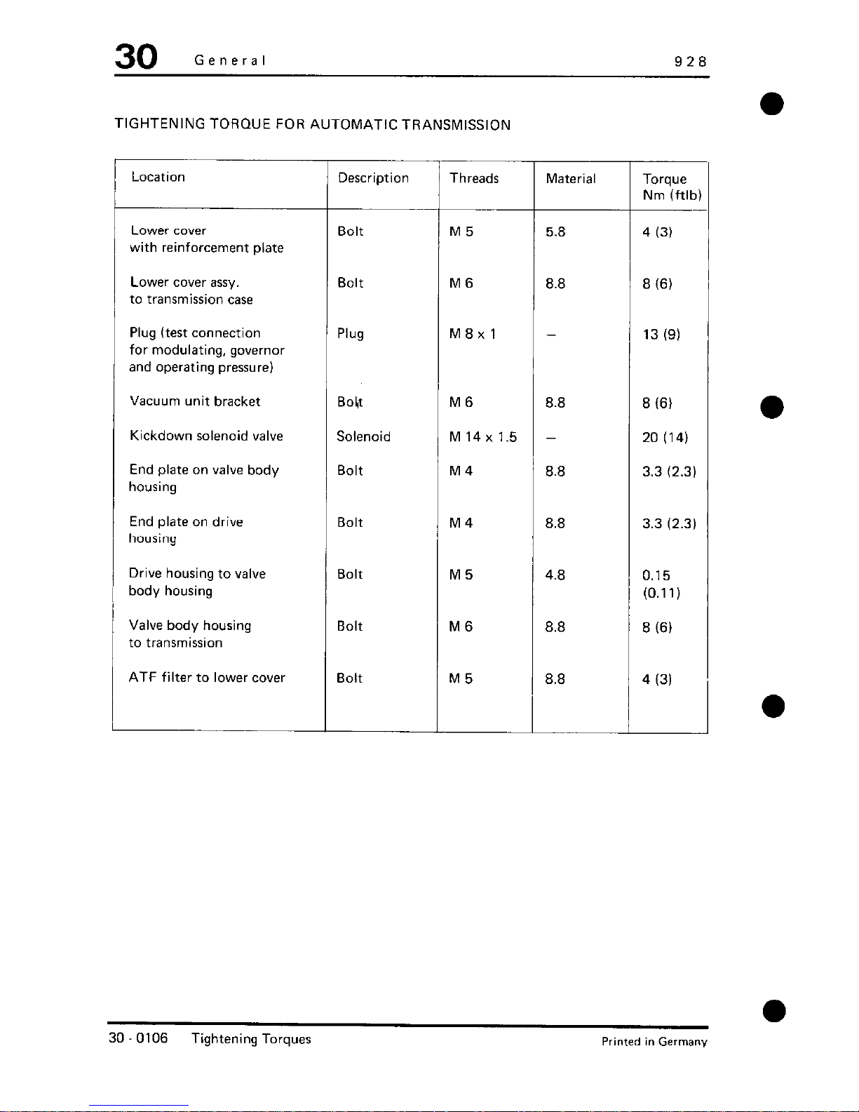
TIGHTENING TORQUE FOR AUTOMATIC TRANSMISSION
Location
Description
Threads
Material Torque
Nm (ftlt
Lower cover
with reinforcement plate
Bolt
M5
5.8
4 (3)
Lower cover assy.
to transmission case
Bolt
M6
8.8
8 (6)
Plug (test connection
for modulating, governor
and operating pressure)
Plug M8xl
-
13 (9)
Vacuum unit bracket
Kickdown solenoid valve
End plate on valve body
housing
Bokt
Solenoid
Bolt
M6 8.8
8 (61
M14x1.5 -
20 (14)
M4
8.8
3.3 (2.3)
End plate on drive
housing
Bolt M4
8.8
3.3 (2.3)
Drive housing to valve
body housing
Valve body housing
to transmission
Bolt M5
4.8
0.15
(0.1 I)
Bolt
M6
8.8
8 (6)
ATF filter to lower cover
Bolt
M5
8.8
4 (3)
d
0
30 - 0106
Tightening Torques
Printed in Germany

928
General Data
30
a
Tightening torques (automatic transmission)
Location
Threaded plug (ATF pan)
ATF pan to transmission case
Front converter casing to
transmission case
Carrier plate to converter
Rear transmission cas to
transmission case
Bearing assembly to
rear transmission case
Final drive to transmission
case
Collar nut (drive pinion)
ATF filler tube to ATF pan
ATF reservoir to ATF pan
Thread
MlOxl
ME
M8
M8
M 10
ME
M 10
M 26x 1.5
M 24
M6
* As of MY ‘92 (transmission type A28.18) = 450 Nm (332 ftlb),
Tightening Torque Nm (ftlb)
22 (12)
8 (5.9)
23 (17)
46 (34)
42 (31)
33 (24)
46 (34)
380* (280)
78 (58)
6 (4.4)
0
Tightening torques (automatic transmission)
30-0107
Printed in Germany - XXXI, 1993

928
Torque Converter
32
a
TOOLS
No.
Description
Special Tool
Remarks
1
Transmission
holder
9216
2
Grip plate
9301
3
Mandrel
9310
4
Depth
gauge
-
Standard
tool
a
Printed in Germany -
VIII, 1984
Removing and Installing Torque Converter
32 101

32
Torque Converter
928
REMOVING AND INSTALLING TORQUE CONVERTER
I-
i .-.-. -.-.-.- .-.-.-.
-‘-‘-‘-‘-‘-
/I-.
I
i
y.<- ’
i
.c’
0-I
@ -9
1
4123
/
!
I
:/-
j
a
32-102
Removing and Installing Torque Converter
Printed in Germany

928
Clutch, Automatic Torque Converter
32
NC
Description
!tY.
I
i
4
a
5
l I5
Mounting bolt
Panhead bolt 8
Washer 8
Front converter
casing
Torque
converter
lutomatic
transmission
T
6
1
1
1
-
Removing
Note When:
Installing
Lift out carefully
with Special Tool
9301
Tightening torque:
46 Nm (34 ftlb)
Tightening torque:
23 Nm (17 ftlb)
Renew if badly worn
or if particles are
found in ATF
Lubricate drive flange
and bearing pin with
MoS multi-purpose
i
gre se.
Place
transmission upright
and insert carefully
using Special Tool
9301.
Note
installation depth.
Printed in Germany
- XVI,1987
Removing and Installing 32 - 103
Torque Converter

32
Clutch, Automatic Torque Converter
928
a
/
NOTES ON REMOVING AND INSTALLING
r
I'
Removinq
l.Remove transmission.
./ ,. , J
,/ ‘”
-yp? pf./
w
/ ;gzp,$ :
2.Using Special Tool 9216, attach
transmission to assembly support.
6.Attach Soecial Tool 9301 to
torque converter and carefully
lift out converter.
3.Place transmission upright and
working through the openings in ~~
the converter casing, remove
converter mounting bolts.
!
4.Remove mounting bolts for
converter casing and remove
casing.
Installinq
Note:
5.Measure installation depth of
converter and make a note for
reassembly.
Up to '86 models = approx. 16 mm
'87 models onward = approx. 28 mm
If the ATF smells burnt or if the
fluid contains particles of pad
material, torque converter and ATF
cooler must be rinsed.
If particles of metal are found in
the ATF pan, the torque converter
must be replaced. Rinsing will not
remove all metal particles and
damage to the transmission may
result.
32 - 104 Removing and Installing
Torque Converter
Printed in Germany

928
Clutch, Automatic Torque Converter
32
l.Rinse torque converter with
Special Tool 9310. To rinse, fill
converter with approx. 11 of
kerosine, insert the rinsing pin
and use a hand drill to turn the
pin at low speed. Then drain
kerosine off through drain plug.
Repeat rinsing 2 - 4 times until
the kerosine drained from the
converter is clean.
2.Attach Special Tool 9301 to
torque converter.
3.Coat drive flange and bearing
pin of converter with MoS2
multi-purpose grease.
4.Place transmission upright and
carefully insert converter,
turning unit in both directions
to engage the teeth.
5.Check installation depth of
converter.
Up to '86 models = approx. 16 mm
'87 models onward = approx. 28 mm
Printed in Germany - XVI,1987
Removing and Installing
32 - 105
Torque Converter
928 Automatic Transmission/Controls, Case
37
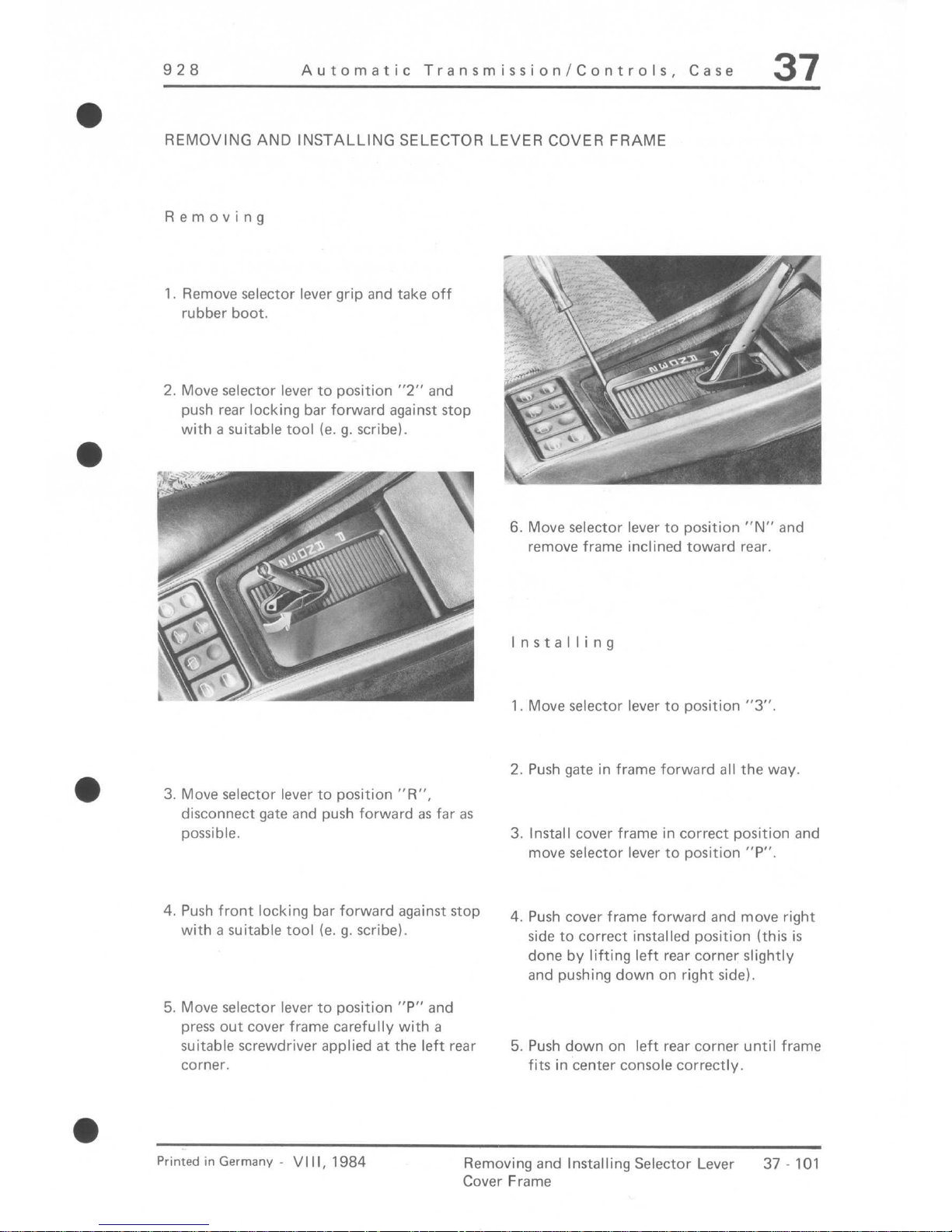
REMOVING AND INSTALLING SELECTOR LEVER COVER FRAME
Removing
1. Remove selector lever grip and take off
rubber boot.
2. Move selector lever to position “2” and
push rear locking bar forward against stop
with a suitable tool (e. g. scribe).
3. Move selector lever to position “R”,
disconnect gate and push forward as far as
possible.
4. Push front locking bar forward against stop
with a suitable tool (e. g. scribe).
5. Move selector lever to position “P” and
press out cover frame carefully with a
suitable screwdriver applied at the left rear
corner.
6. Move selector lever to position “N” and
remove frame inclined toward rear.
Installing
1. Move selector lever to position “3”.
2. Push gate in frame forward all the way,
3. Install cover frame in correct position and
move selector lever to position “P”.
4. Push cover frame forward and move right
side to correct installed position (this is
done by lifting left rear corner slightly
and pushing down on right side).
5. Push down on left rear corner until frame
fits in center console correctly.
Printed in Germane - VIII, 1984
Removing and Installing Selector Lever
37-101
Cover Frame

37
Automatic Transmission/Controls, Case
928
6. Position selector lever between “R” and
“P”, disconnect gate on selector lever and
push forward.
7. Push front locking bar toward rear until it
engages.
8. Move selector lever to position “3” and
push rear locking bar toward rear until it
engages.
a
9. Attach gate in selector lever, install
rubber boot in correct position and
install selector lever grip.
IO. Move selector lever in and out of all
positions and make sure that cover frame
fits properly.
a
a
A - Locked
6 - Unlocked
37 - 102
Removing and Installing Selector Lever Cover Frame
Printed in Germany

928
Automatic Transmission/Controls, Case
37
REMOVING AND INSTALLING SELECTOR LEVER CABLE
Removing
1. Unscrew ground strap of battery on body.
2. Remove selector lever grip and take off
rubber boot.
3. Remove cover frame (see page 37 101).
4. Pull bulb holder carrier out of retaining
clips.
5. Mark location of selector lever base for
reinstallation and remove mounting screws.
6. Loosen intermediate muffler shield and
push aside as far as possible.
7. Disconnect selector lever cable on trans.
mission lever and detach cable sleeve on
brackets.
23
--- 7 -:+@*> : ---,
i
F ,/’
c-
8. Take off ball head, hexagon nut and
mounting parts.
9. Attach tailing wire on cable and pull out
selector lever base with cable by pulling
forward at an angle.
10. Remove cable circlip on selector lever
and detach cable sleeve on selector lever
base.
a
Printed inGermany VIII, 1984
Removing and Installing Selector
37 103
Lever Cable

37
Automatic Transmission/Controls, Case
928
Note:
Installing
1. Attach cable sleeve on selector lever base,
tightening the hexagon nut carefully.
2. Push cable on to selector lever pin and
install circlip.
3. Attach tailing wire, pulled forward during
removal, on cable and pull cable toward
rear, whereby one person should guide in
the selector lever base and a second person
must pull wire and cable.
4. Install selector lever base in correct
position (watching mark) and tighten
mounting screws with 15 Nm/ll ftlb.
5. Install cover frame and selector lever grip.
Place selector lever at “N”.
If light opening of gate and letter “N” are
not exactly opposite each other in cover
frame, remove cover frame again and reposition selector lever base in slots.
6. Mount selector lever cable on transmission
as specified.
7. Adjust selector lever cable (see page
37 - 105).
37 - 104
Removing and Installing Selector Lever Cable
Printed in Germany

928
Automatic Transmission/Controls, Case
37
ADJUSTING SELECTOR LEVER CABLE
1. Move selector lever to position “N”.
2. Place range selector lever on transmission
in “N”.
Note:
Bolt for range selector lever must be
tightened for adjustments.
3. Adjust ball end on cable that attachment is
possible without tension.
l
Printed in Germany - VI II, 1984
Adjusting Selector Lever Cable
37 - 105

928
Automatic Transmission/Controls, Case
37
REMOVING AND INSTALLING STARTER LOCKING AND BACKUP
LIGHT SWITCH
Removing
1. Disconnect selector lever cable.
- in
I q&.‘.
2. Remove bolt for range selector lever and
pull off lever.
3. Unlock plug by turning white plastic ring
(arrow) upwards in direction of arrow.
IWJ
--- --
I
4. Pry off plug carefully with two screw
drivers applied on cable outlet and bar.
‘/ -
-,fy!y;@-@+-q
i3
.-w-y _.. YQ;)(: ..
2
? .-”
-a
? --’
-‘,&
+ of j,%gg$ -’
.:‘y $g ,(
5. Remove switch mounting screws and take
off switch.
Installing
1. Install switch with both mounting screws,
but do not tighten.
Printed in Germany -
VI I I, 1984
Removing and Installing Starter Locking
37.107
and Backup Light Switch
37
Automatic Transmission/Controls, Case
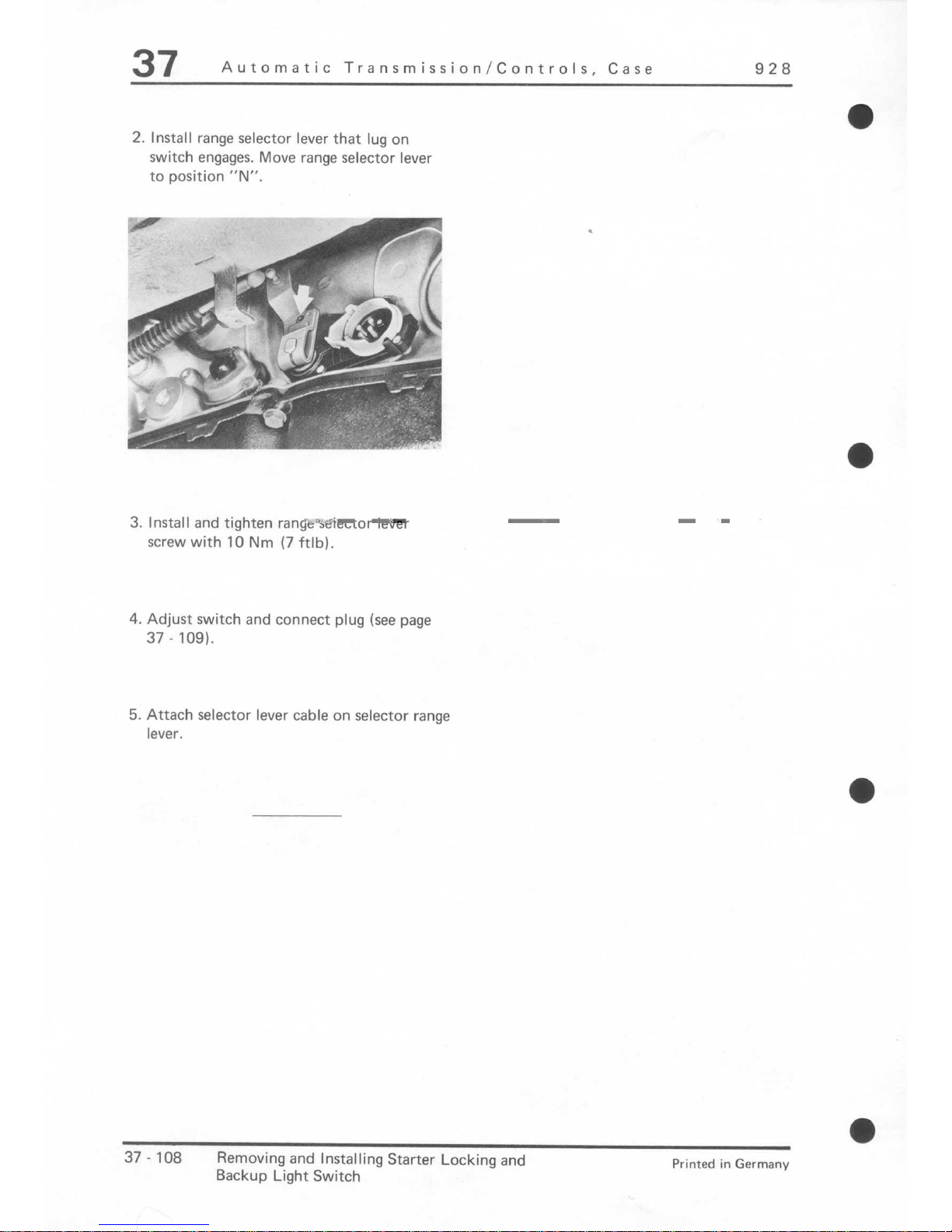
928
2. Install range selector lever that lug on
switch engages. Move range selector lever
to position “N”.
3. Install and tighten range selector lever
screw with 10 Nm (7 ftlb).
4. Adjust switch and connect plug (see page
37 - 109).
5. Attach selector lever cable on selector range
lever.
a
37.108
Removing and Installing Starter Locking and
Backup Light Switch
Printed
in Germany

928
Automatic Transmission/Controls, Case
37
ADJUSTING STARTER LOCKING AND BACKUP LIGHT SWITCH
I. Insert locating pin made of 4 mm dia.
welding wire for 4 mm dia. drill) through
lug into locating bore in switch housing.
2. Tighten switch mounting screws with
10 Nm (7 ftlb) and pull out locating pin.
3. Press on plug and turn white plastic ring
down.
Printed inGermany
VIII, 1984
Adjusting Starter Locking and Backup 37 - 109
Light Switch

928 Automatic Transmission/Controls, Case
37
CHECKING ADJUSTMENT OF SELECTOR LEVER CABLE AND
STARTER LOCKING/BACKUP LIGHTSWITCH
Move selector lever to position “N”. Run
engine at fast idle speed.
Pull up parking brake lever and press down
on brake pedal for following tests.
6. Starting engine should only be possible
in “p” or ,TN”,
7. Backup lights must be on in position “R”.
1. Move selector lever to position “R”. Engine
speed must drop as gear engages.
2. Move selector lever to position “P”. Engine
speed should increase as reverse gear
disengages.
3. Repeat test in point I.
4. Move selector lever to position “N”. Engine
speed should increase as reverse gear
disengages.
5. Move selector lever to position “D”. Engine
speed should drop as gear engages.
Printed in Germanv VIII, 1984
Checking Adjustment of Selector Lever
37 111
Cable and Starter Locking/Backup Light Switch

928
Automatic Transmission/Controls, Case
37
a
NOTES ON REMOVING AND INSTALLING
Removing
l.Remove top and bottom halves of air
filter(l6-valve engines only)
2.Disconnect control cable at engine.
16-valve engines
!
2B~~fi~
i)
1.
l 1 ,;.? .y;-_ /F; .._ 1, *;\,
!
[‘: .__.
t’
; i ‘T
,..:s,
‘Y., I
h. b, I’ ” yi -‘13
.e
‘/.LI,,,j;,;,,; 4
F
T.;,- .-a “.-- ~1
32-valve engines (up to '86 models)
. . .
;.d
.A,.
.;
tr
/#-., CA”
I
32-valve engines ('87 models onward)
3.Sever bowden cable behind threaded
connector.
4.Disengage control cable from transmission by pressing locking
tab of guide as arrowed (arrow A)
and turning guide anti-clockwise
(arrow B).
Printed in Germany - XVI,1987 Bowden Cable for Control Pressure, 37 - 113
Removing and Installing
(Service Solution)
37
Automatic Transmission/Controls, Case
928
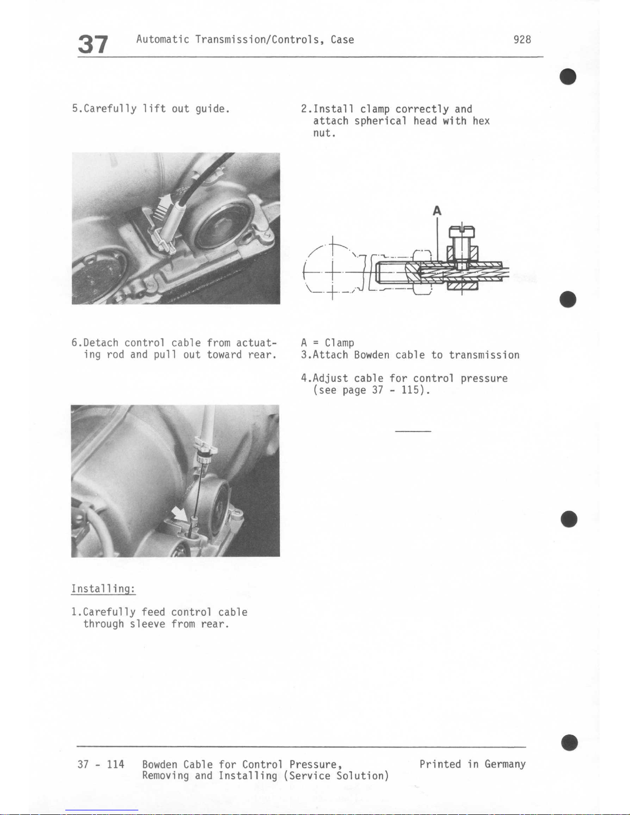
5.Carefully lift out guide.
6.Detach control cable from actuating rod and pull out toward rear.
Installing:
l.Carefully feed control cable
through sleeve from rear.
2.Install clamp correctly and
attach spherical head with hex
nut.
A = Clamp
3.Attach Bowden cable to transmission
4.Adjust cable for control pressure
(see page 37 - 115).
37 - 114 Bowden Cable for Control Pressure,
Printed in Germany
Removing and Installing (Service Solution)
928
Automatic Transmission/Controls, Case
37
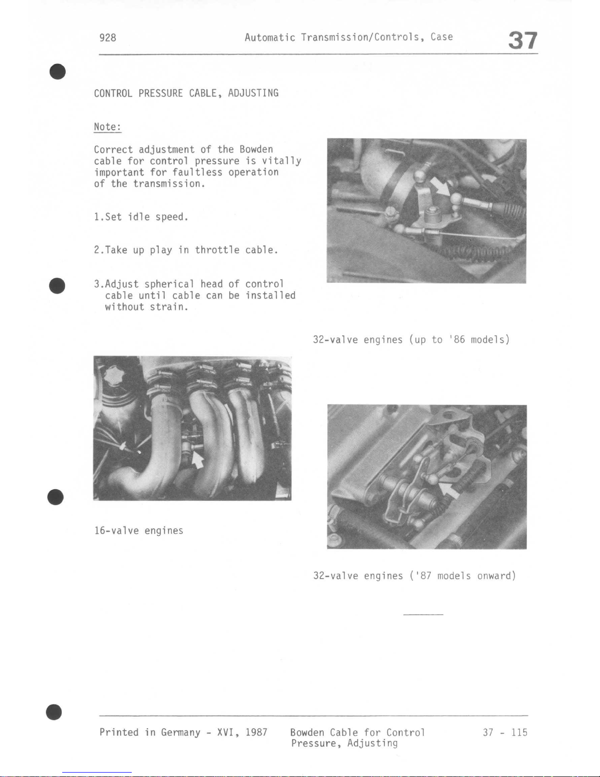
CONTROL PRESSURE CABLE, ADJUSTING
Note:
Correct adjustment of the Bowden
cable for control pressure is vitally
important for faultless operation
of the transmission.
l.Set idle speed.
2.Take up play in throttle cable.
3.Adjust spherical head of control
cable until cable can be installed
without strain.
32-valve engines (up to '86 models)
m
’ 6 .I
-
.%
” ,
-t
.? .!
r ’
” h!
.+d: 1
-1
16-valve engines
.
I
32-valve engines ('87 models onward)
Printed in Germany - XVI, 1987 Bowden Cable for Control
37 - 115
Pressure, Adjusting
 Loading...