

Porsche 930 TURBO - 1989 GENERAL DATA, 930, 1977 930, 1978 930, 911 Turbo 1989 User Manual

General Data
TRANSMISSION TYPE 930
The following transmissions are installed in the 930 Turbo:
930/30 -4-speed with rear axle final drive 9/38 (standard)
930/32 -4-speed with rear axle final drive 9/36 (not for USA)
The following transmission is installed from 1977 Models:
930/33 -4-speed with a final drive ratio of 9/38
From 1978 Models with the following transmission:
930/34 -4 gears with final drive ratio of9/38

General data
911 turbo
Five-speed transmission G50/50
88-227
A new five-speed transmission has been installed in the 911 Turbo worldwide from Model 89 onward.
This gearbox corresponds to the G 50/00 Carrera gearbox with regards to construction and repair.
The gearbox has been reinforced, however, and the transmission ratios modified to suit the
high engine performance of the turbo engine.
Refer to the Carrera workshop manual (Page 30-0102) for maintenance information.
Five-speed transmission G50/50
Printed in Germany -VII, 1989
30-02

General Data
MANUAL TRANSMISSION TORQUE SPECIFICATIONS
Location
Designation
Threads
Material
Torque
NM (kpm)
Drive shaft
Nut
M 30xl.5
8.8
210 -230
(21.0 -23.0)
Drive shaft
Nut
M 20xl.5
C 35 V
160-180
(16-18)
Driven shaft
Nut
M 24xl.5 8
190-100
(19-20)
Stub axle
Stub axle
Stretch bolt
Hex hd screw
M IOxl.5
M IOu. 5
8.8
8.8
(2. 6 -3. 0)
(3. 0 -4. 6)
26-30
39-46
Transm. case
Vent
M 14xl.5 9 S 20 K
20-30
(2 -3)
Gearshift rod
Conical scr.
M 8xl.25
8.8
23-26
(2.3-2.6)
Shift cover Mid-grip nut
M 8xl.25 X 12 Cr
No 18.8
22-25
(2.2-2.5)
Backup light
switch
Gear housing
M 18xl.5 MS 25-35
(2.5-3.5)
Gearshift
forks
M 6xl.O
8.8
9-11(0.9-1.1)
Hex nut
M 8xl.25
8 22-25
(2.2-2.5)
Clamp, gears, transm.I
case, front and side
covers
Hex nut
Shift lock,
transm. case
Hex hd screw
M lOxl.5
8.8
15-18
(1.5-1.8)
24-26
(2.4-2.6)
Hex hd screw
M 8xl.25
8.8
Selector
forks
11.9
135-140
(13.5-14)
Ring gear,
differential
Hex hd screw M 12xl.25
12.9
150-160
(15-16)
Hex hd screw M 12xl.25
5t 37-5.8
20-25
(2-2.5)
Plug with
magnet
M 24x1.5
Con. 1:16
Transm. case
oil drain
5.8
20-25
(2-2.5)
Plug
M 30x1.5
Con. 1:16
Gear housing
Oil filler
5.8
20-25
(2-2.5)
Plug
M 16xl.5
Reverse gear
Lock
Technical Data
30-03
Printed in Germany -IV. 1981

Location
Designation
Threads
Material
Torque
Nm (kpm)
Guide tube
Capscrew
M 6xl.O
8.8
8-10
(0.8-1.0)
Clutch and
starter gear
Capscrew
M 8xl.O
8.8
20-'-5
(2.0-2.5)
Starter
Hex nut
M lOxl.5
8
46-50
(4.6-5.0)
Mech. controls
Holder to base
Hex hd screw
M6
8.8 6
(0.6)
Base to tunnel
Socket head
capscrew
M8
8.8 21
(2.1)
ICon. screw in
shift rod end
Con. screw
M8
8.8
15
(1.5)
COIl. screw in
coupling
Con. screw
M8
8.8 15
(1.5)
Clamp
Hex hd screw
M8
8.8
25
(2.5)
30-04 Technical Data
Printed in Germany
General
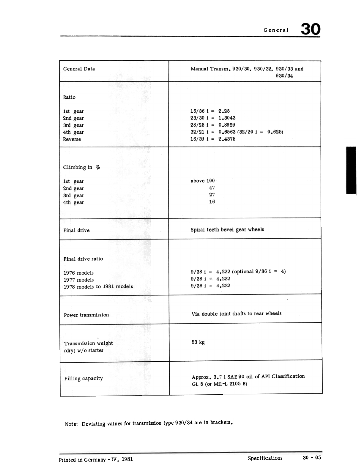
General Data Manual Transm. 930/30, 930/32. 930/33 and
930/34
Ratio
1st gear
2nd gear
3rd gear
4th gear
Reverse
16/36 i = 2.25
23/30 i = 1.3043
28/25 i = 0.8929
32/21 i = 0.6563 (32/20 i = 0.625)
16/39 i = 2.4375
Climbing in 0;0
abo
1st
2nd
3rd
4th
Spiral teeth bevel gear wheels
Final drive
Final drive ratio
9/38 i = 4.222 (optional 9/36
9/38 i = 4.222
9/38 i = 4.222
= 4)
1976 models
1977 models
1978 models to 1981 models
Via double joint shafts to rear wheels
Power transmission
53 kg
Transmission weight
(dry) w /0 starter
Approx. 3.7 1 SAE 90 oil of API Classification
GL 5 (or Mil-L 2105 B)
Filling capacity
Note: Deviating values for transmission type 930/34 are in brackets.
30 -05
Specifications
Printed in Germany -IV. 1981
ve
100
47
27
16
gear
gear
gear
gear

General Data
Technical Data
Printed in Germany -III. 1978
30-07

1
-III, 1978Printed in Germany
Removing and Installing Clutch Disc 30 -1

30 Clutch, Control
Removing and Installing Clutch Disc
Printed in Germany
30 -2

Clutch, Control
Notes when
No.
Description
I
Qty.
Remarks
Removing
Installing
1
Clutch bolts
6
Unscrew evenly
Tighten evenly and
diagonally
torque: 2.0-2.5 mkg
(14 -18. 5 ft Ibs)
la
Clutch bolts
DIN 931 from
Trans. No. 776
0013 or 776 1011
9
Unscrew evenly
Tighten evenly and
diagonally.
torque: 2,0-2, 5 mkg
(14 -18, 5 ft Ibs)
2
Washer
6
Replace, if needed
3
Ring gear
1
Check for wear
4
Pressure plate 1
5
Throwout bearing 1
Don't wash. Wipe
with dry rag. Coat
guide tube contact
surface with MoS
lubricant. 2
Don't subject to
pressure -danger
of damage!
6
Clutch disc Check for wear.
Center with clutch
centering tool 9102
1
Removing and Installing Clutch Disc
30 -3
Printed in Germany -IV, 1981

Clutch, Control
REMOVING AND INSTALLING
Removing
Note
1. Hold flywheel with toothed segment P 201 a
and spacer sleeve. Make sure that spacer sleeve
fits engine with adequate clearance.
Clutch linings cannot be replaced.
If applicable, the entire disc is to be replaced.
2. Loosen bolts holding clutch pressure plate to
flywheel evenly and diagonally one or two
threads, until the spring pressure stops (pre-
vents distortion on clutch pressure plate).
5. Check disc with lining for lateral runout.
Permissible lateral run out on 225 mm .
diameter is max. 0.6 mm.
CHECKING CLUTCH DISC
1. Check teeth. The clutch disc must move
easily in axial direction on drive shaft with-
out radial play.
2. Check rivets. Replace clutch disc if in
doubt.
3. Check clutch lining. If clutch lining has oil
spots, is burnt, torn or worn at spots, install
a new disc.
4. Check lining thickness. Thickness of di'lc
+
with riveted lining (no tension) is 10.1 -
0.3 mm. Wear limit (no tension) is 8.5 mm
for symmetrical wear.
Printed in Germany
Removing and Installing Clutch Disc
30 -4

Clutch, Control
CHECKING CLUTCH PRESSURE
PLATE/DISC
The MFZ clutch pressure plate from Fichtel and
Sachs is not designed for reconditioning or repairing.
The inspection is limited to dry cleaning and
removing dust with compressed air and emery
cloth, and a thorough visual! examination.
1. Clean clutch. If necessary. clean bearing
surface of pressure plate with emery cloth.
Remove burnt spots by polishing. Clean entire
assembly thoroughly with compressed air.
2. Check ends of diaphragm springs for traces
of wear from clutch release bearing. Wear
up to a depth of 0, 3 mm is not serious.
4. Check spring connections between pressure
plate and cover for cracks. Check tightness
of rivet connections. Replace pressure plates
with damaged or loose rivets.
3. Check friction surface of pressure plate for
cracks, burnt spots and wear. Check with
steel ruler. Pressure plates which are tapered
up to 0, 3 mm toward inside, can still be
used (check with feeler gauge blade).
-I, 1976
Removing and Installing Clutch Pressure Plate and Disc 30 -5
Printed in Germany

30 Clutch, Control
Installing
1. After cleaning. check clutch contact surface
of flywheel for wear. If necessary, machine
surface and smooth with emery cloth. Replace
the flywheel, if necessary.
2. Lubricate needle bearing in flywheel with
about 1 cm3 (1,5 grams) of MoS2 grease.
3. Install clutch with special tool 9102 to
center in flywheel.
4. Center clutch pressure plate on flywheel.
5. Tighten bolts evenly and diagonally to prevent
distortion on cover. Tighten bolts to specified torque. Use Special Tool P 201 a and a
spacing sleeve to hold the flywheel.
30 -6
Printed in Germany
Removing and Installing Clutch Pressure Plate and Disc

Clutch. Controls
ADJUSTING CLUTCH FROM 1977 MODELS (with clutch servo on transmission)
Note
Because of the clutch servo it is no longer
possible to check the clutch play exactly at the
clutch pedal. This is why the clutch play of
cars with a servo clutch has to be checked at
the transmission adjusting lever.
Check and adjust clutch, see Repair Manual 911,
Main Group 7 -Page 2.1 -2/3.
30 -7
Printed in Germany -II. 1976

DISASSEMBLING AND ASSEMBLING CLUTCH
Disassembling and Assembling Clutch
III, 1978 -
Printed in Germany
30 -8

Note When
Removing
Special
Instructions
No.
Description
Qty.
Installing
1
Bolt
9
2
Washer
9
If necessary. replace
3
Pressure plate
1
4
Drive plate
1
Check for wear.
center with a mandrel
5
Starter gear ring
1
6
Release bearing
1
Only possible,
when pressure
plate not loaded
(without 3
brackets)
Check. replace if
necessary. Do not
wash, only wipe off
dry. Coat sliding
surfaces for guide tube
with MoS multipur-
2
pose grease
Don't subject to
pressure -danger
of damage!
7
Capscrew
9
8
Flywheel
1
DISASSEMBLING AND ASSEMBLING CLUTCH
1. Three clips can be used to facilitate installation of clutch pressure plate.
These clips are mounted on all spare part
clutch pressure plates and must be removed
after installation. It is recommended to keep
these clips on hand for later repair jobs.
2. Since the clutch ~oncerned is pulled and the
release bearing is designed accordingly. the
release bearing must never be subjected to
pressure in direction of drive plate.
Consequently never place removed pressure
plate on release bearing.
When installing or assembling engine and
transmission also make sure that release lever
is not exerting force on bearing.
Printed in Germany -IV. 1981
Disassembling and Assembling Clutch
30 -9
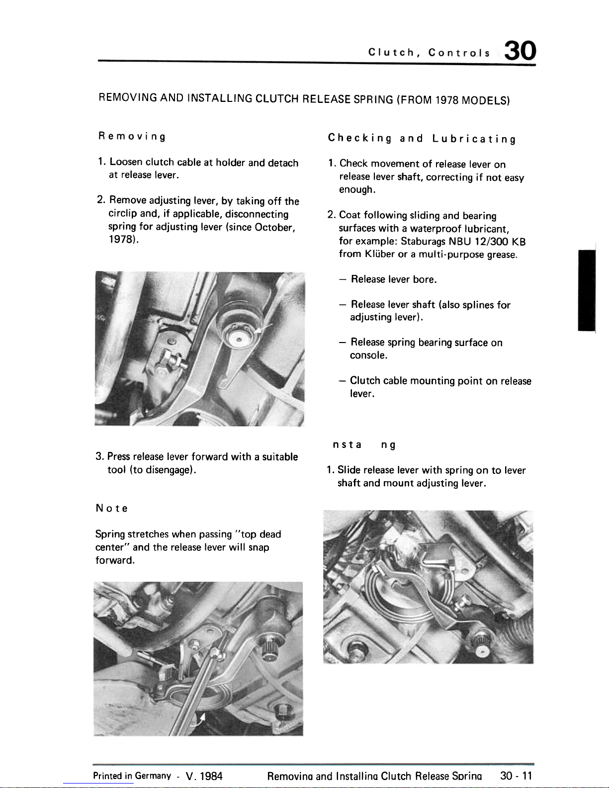
REMOVING AND INSTAlliNG CLUTCH RELEASE SPRING (FROM 1978 MODELS)
Removing
Checking and Lubricating
1. Loosen clutch cable at holder and detach
at release lever.
1. Check movement of release lever on
release lever shaft, correcting if not easy
enough.
2. Remove adjusting lever, by taking off the
circlip and, if applicable, disconnecting
spring for adjusting lever (since October,
1978).
2. Coat following sliding and bearing
surfaces with a waterproof lubricant,
for example: Staburags NBU 12/300 KB
from Kli.iber or a multi-purpose grease.
-Release lever bore.
-Release lever shaft (also splines for
adjusting lever).
-Release spring bearing surface on
console.
-Clutch cable mounting point on release
lever.
nsta
ng
3. Press release lever forward with a suitable
tool (to disengage).
1. Slide release lever with spring on to lever
shaft and mount adjusting lever.
Note
Spring stretches when passing "top dead
center" and the release lever will snap
forward.
Printed in Germany -V. 1984
Removina and Installina Clutch Release Sorina
30-11

Clutch, Controls
2. Press back release lever with a suitable tool
until release spring passes the top dead
center point (lever snaps against stop on
console) .
3. Remove adjusting lever again and mount
as close as possible to release lever.
4. Make basic clutch adjustment.
Removing and Installing Clutch Release Spring
Printed in Germany
30-12
Clutch
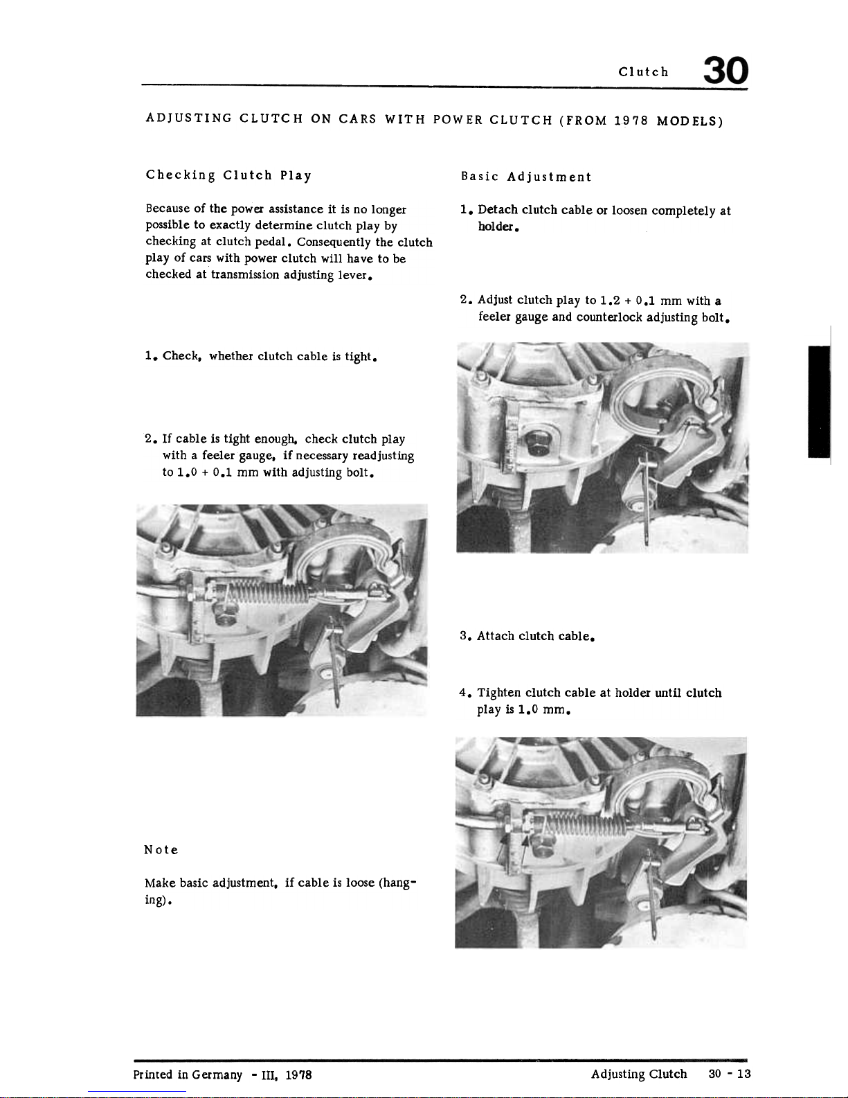
ADJUSTING CLUTCH ON CARS WITH POWER CLUTCH (FROM 1978 MODELS)
Checking Clutch Play
Basic Adjustment
1. Detach clutch cable or loosen completely at
holder.
Because of the power assistance it is no longer
possible to exactly determine clutch play by
checking at clutch pedal. Consequently the clutch
play of cars with power clutch will have to be
checked at transmission adjusting lever.
2. Adjust clutch play to 1.2 + 0.1 mm with a
feeler gauge and counterlock adjusting bolt.
1. Check, whether clutch cable is tight.
2. If cable is tight enough, check clutch play
with a feeler gauge, if necessary readjusting
to 1.0 + 0.1 mm with adjusting bolt.
3. Attach clutch cable.
4. Tighten clutch cable at holder until clutch
play is 1.0 mm.
Note
Make basic adjustment, if cable is loose (hang-
ing) .
Adjusting Clutch
30 -13
Printed in Germany -Ill. 1978

Note
5. Measure release travel.
Clutch cable tightness is correct, if when engaged
the release lever just lifts off of stop.
a) Apply calipers with clutch engaged (see
figure) and read distance I (e.g. 101.9 mm).
b) Disengage clutch and measure distance II
as shown in figure (e.g. 74.7 mm).
Note
If adjusting room on clutch cable holder is not
sufficient, also adjust front end at pedals. For
this purpose, adjust stop on floor plate that relea-
.+
se travel on release lever lS 27 -0.5 mm.
c) Dimension I less dimension II (in example,
101.9 mm minus 74.7 mm= 27.2 mm)
gives the release travel.
Printed in Germany
Adjusting Clutch
30 -14

911 turbo
Clutch, Control
Clutch mechanism, disassembling and assembling, from Model 89 onward
C!f~
1 2
155/30
30 -15

Clutch, Control
911 turbo
Note when:
I Installing
No.
Description
Oty.
Removing
1
Hexagon head screws
M 6 x 16
1
2
Bracket
1
Install in correct position
3
Bearing cover 1
Pack with grease, use
Olista Longtime 3 EP
Needle bearing with as-
sembly hole
4
1
Install in correct posi-
tion, assembly hole
points outwards
5
Clutch release lever shaft
Pull out with hexagon he-
ad bolt
M6x40
1
6
Sealing ring
2 Check, replace if neces-
sary, install in correct po.
sition
7
Clutch release lever
1
8 1
9
Needle bearing without as-
sembly hole
Plastic bushing 1
I nstall in correct posi-
tion, closed side points
towards needle bearing,
bushing not installed on
gearboxes with through
bore
Note
Lubricate all sliding surfaces of the clutch release mechanism with Olista Longtime 3EP,
Part Number 000.043.024.00
Clutch mechanism, disassembling and assembling, from Model 89 onward
Printed in Germany -VII, 1989
30 -16
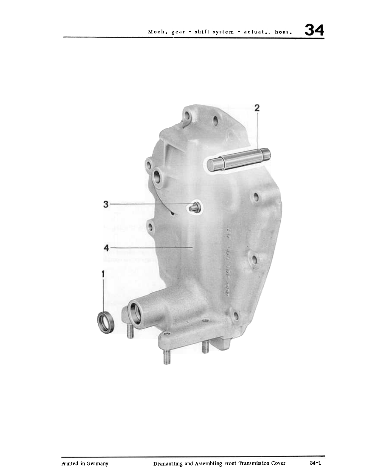
gear -shift system -actuat.. hous.
Printed in Germ~ny
Dismantling and Assembling Front Transmission Cover
34-1

Mech. gear -shift system -actuat.. hous.
Notes
No.
Designation
Amt.
Remarks
Removing
Installing
1
1
Sea]
Pry out with
screwdriver .
Drive onto stop
with appropriate
mandrel
Reverse shaft
1
2
Drive out.
Heat cover to
0
ca. 120 C and
drive in
3
Operating
lever spacer
1
Drive out
Heat co~er to
ca. 120 C and
drive in
I
4
Front housing
cover
1
DISMANTLING AND ASSEMBLING INSTRUCTIONS
Dismantling
1. Pry out seal for main selector rod with a
screwdriver .
Assembling
:J.. Drive in main selector rod seal to stop
with an appropriate mandrel.
2. Drive out reverse gear shaft and operating
lever spacer.
Mech. gear -shift system -actuat.. house
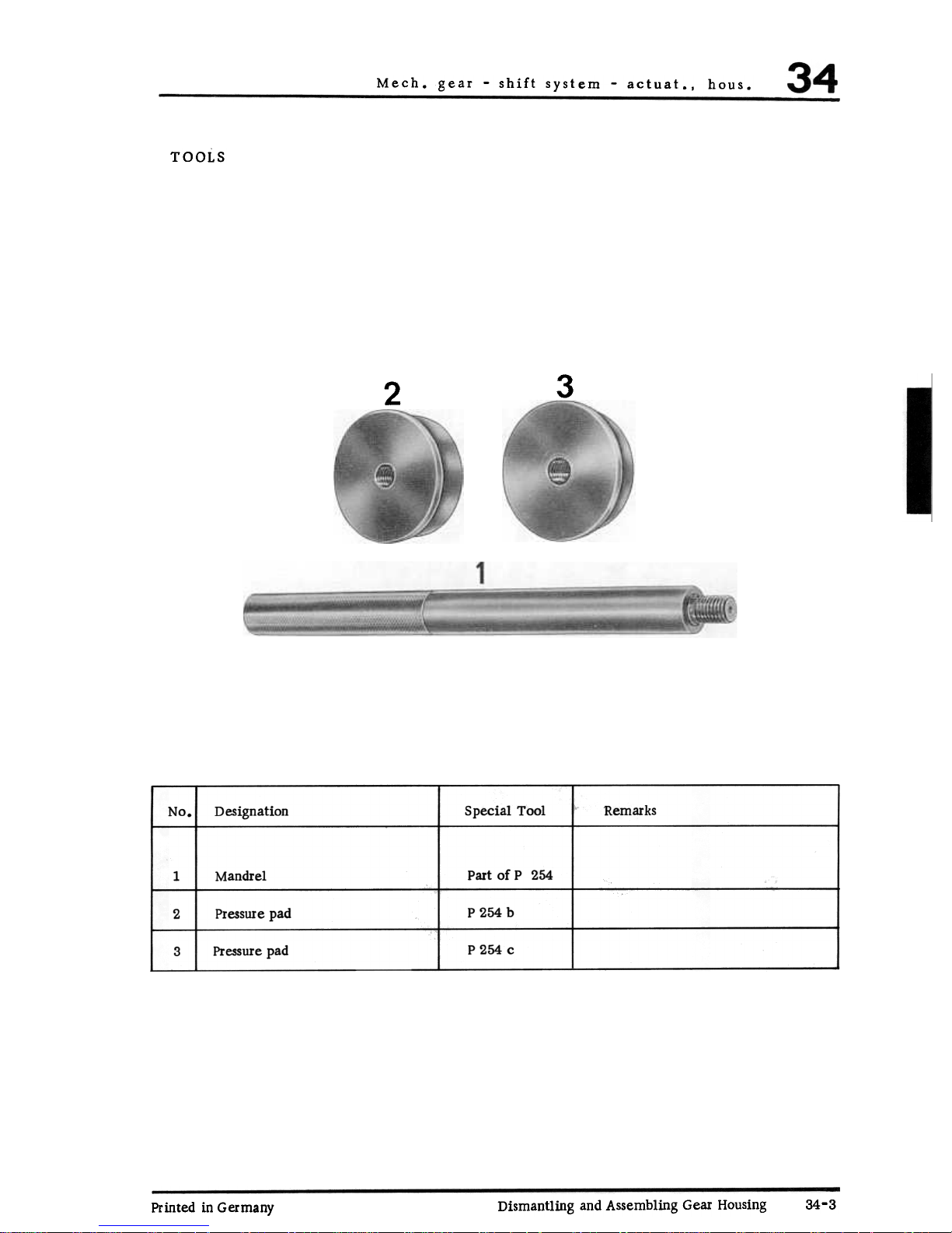
TOOLS
3
2
Designation
Special Tool Remarks
No
Mandrel
Part of P 254
1
Pressure pad
P 254 b
2
Pressure pad
P 254 c
3
Dismantling and Assembling Gear Housing
34-3
Printed in Germany

Manual Transmission/Controls
Case
Printed in Germany
34-4 Dismantling and Assembling Gear Housing

gear -shift system -actuat.. hous.
Notes
Designation
Amt.
Remarks
Removing
Installing
1
Cotter pin
1
Replace
Washer
2
1
3
Operating lever
1
4
Operating lever
shaft
1
Coat with
univexsal
lubricant
Washer
5
1
6
Plug
1
Torque to
specifications
Cotter pin7
1
Replace
8
Pin
1
9
Reverse operating
lever
1
10
ReveIse rod
1
Removing with
small screw-
driver.
11
Snap ring
2
Install
correctly.
12
Outer race with
snap ring
Drive out with
P 254 b.
1 Heat gear hsg. to
0
ca. 120 C and
drive in with
P 254 b.
13 Outer race with
snap ring
Drive out with
P 254 c.
1 Heat gear hsg. to
0
ca. 120 C and
drive in with
P 254 c.
1 Drive out
from inside
14
Operating lever spacer
15
Gear housing
1
34-5
Printed in Germany
Dismantling and Assembling Gear Housing

Mech. gear -shift system -actuat.. hous.
DISMANTLING AND ASSEMBLING INSTRUCTIONS
Dismantling
Note
1. Remove snap rings for bearing outer races
with P 254 b or 254 c.
The bearing outer races have different
inside diameters. The bearing outer race
with the largest inside diameter belongs
to the driven shaft cylindrical roller
bearing.
Assembling
1. Heat gear housing to about 1200 C and
drive in outer races with P 254 b or P 254 c.
Printed in Germany
34-6 Dismantling and Assembling Gear Housing

Mech. gear -shift system -actuat.. hoDs.
TOOLS
No.
Designation
Special Tool Remarks
Pressure pad
P 254 d
1
Local Manufac.
2 Hook
Mandrel
P 375
3
Pressure pad
P 254 a
4
P 265 c
5 Pressure pad
Printed in Germany Dismantling and Assembling Transmission Case
34-7

gear -shift system -actuat.. house
Printed in Germany
34-8 Dismantling and Assembling Transmission Case
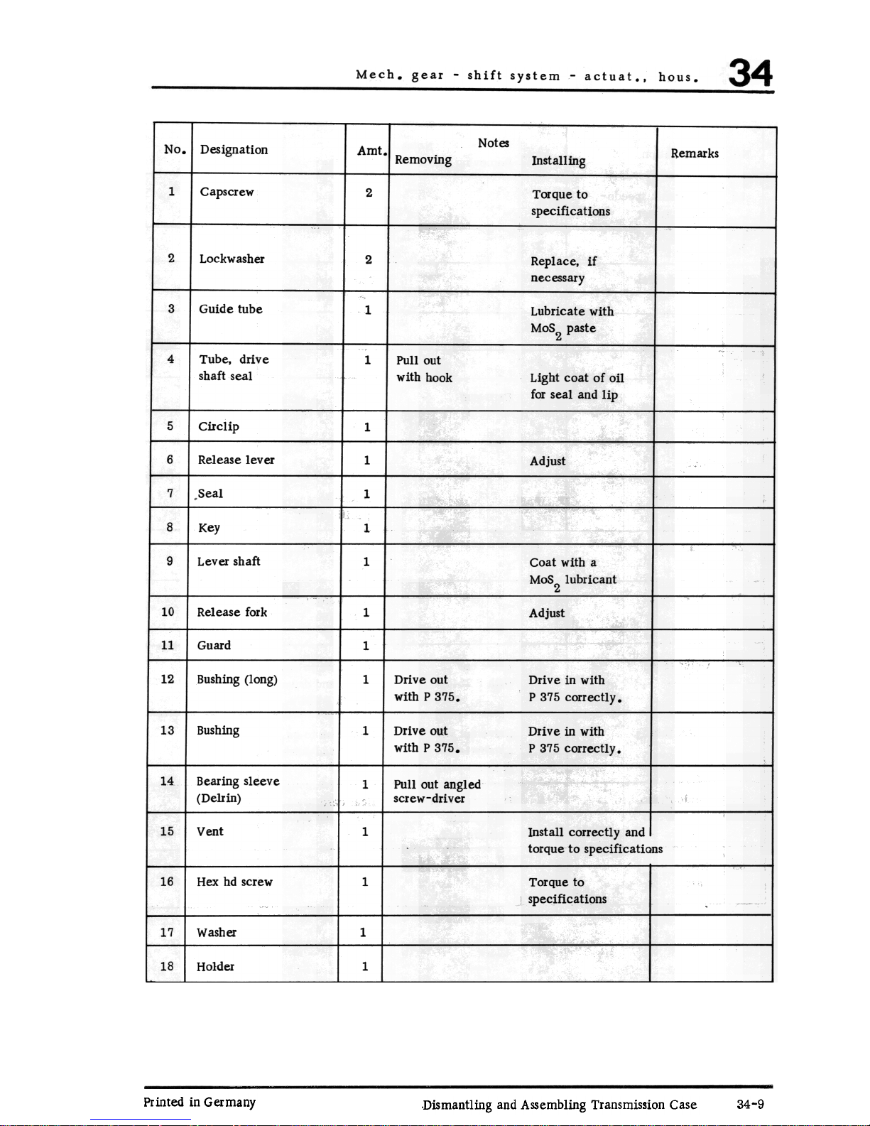
Notes
Designation
Amt
Remarks
Removing
Installing
1
Capscrew
2
Torque to
specifications
2
Lockwasher
2
Replace. if
necessary
3
Guide tube
1
Lubricate with
MoS2 paste
4
Tube, drive
shaft seal
1
Pullout
with hook
Light coat of oil
for seal and lip
5
Circlip
1
6
Release lever
1
Adjust
7
Seal
1
8
Key
1
Lever shaft9
1
Coat with a
MaS lubricant
2
10 Release fork
1
Adjust
Guard11
1
12
Bushing (long)
1 Drive out
with P 375.
Drive in with
P 375 correctly.
Bushing
13
1
Drive out
with P 375.
Drive in with
P 375 correctly.
14
Bearing sleeve
(Delrin)
1 Pullout angled
screw-driver
15 Vent 1
Install correctly and I
torque to specifications
16 Hex hd screw 1
Torque to
specifications
Washer17
1
18
Holder
1
Printed in Germany
34-9
Dismantling and Assembling Transmission Case
 Loading...