

Page 1
www. por a. com
PORA ELECTRIC MACHINERY CO.,LTD.
T
A
T
A
T
Setting manual
Rev 2.2
Tension Controller
PR-DTC-4100.A
PR-DTC-4100.AD
Page 2

Page 3
CONTENTS
Tension Controller
PR-DTC-4100.A
PR-DTC-4100.AD
CONTENTS
Product Characteristic & Precautions ...............3
Before Use .............................................................4
1. Dimensions .........................................................4
2. External connection diagram .........................5
3. Product installation & Wiring...........................6
4. Product Specifications ....................................10
5. Compatible Sensor ...........................................10
6. Guidance on operating part ...........................11
7. Guidance on Display .......................................13
Working & Operation.............................................19
1. Manual/Automatic mode .................................19
2. Setting zero .........................................................20
3. Span Setting .....................................................20
4. Tension calibration (Scale setting) .................21
5. A, B Output switch .........................................22
6. P·I·D Sensitivity setting .............................23
7. Button lock function .........................................24
8. Remote function ................................................24
Setting ......................................................................25
Guidance on a button to be used when setting
a menu ....................................................................25
The way of setting ...............................................26
1. BASIC SET ..........................................................28
2. TENSION CALIBRATION ..................................28
3. TENSION CONTROL ........................................29
4. CONTROL OUTPUT .........................................30
5. PID SET ...............................................................31
6. ANALOG INPUT SEL........................................31
7. ANALOG INPUT SET .......................................32
8. LINE SPEED .......................................................33
9. TAPER ..................................................................34
10. ANALOG OUTPUT..........................................35
11. DIGITAL INPUT ................................................35
12. DIGITAL OUTPUT ............................................36
13. FILTER ...............................................................36
14. USER SET ........................................................37
15. DISPLAY ............................................................38
16. INTERFACE CHECK .......................................38
Using communication ..........................................39
1. Can 2.0A .............................................................39
2. Modbus-RTU (RS-232) .................................40
3. Hyper Terminal (RS-232) ...............................42
4. Ethernet (※Option) ...........................................42
5. Profibus-DP (※Option) ...................................42
The rest ....................................................................43
1. Sheet for recording internal setting ..............43
2. Checking abnormalities ...................................46
3. Table for standard of tension .........................47
Page 4

Page 5
3
PORA ELECTRIC MACHINERY CO.,LTD.
PR-DTC-4100.A / AD
(Please read this manual carefully before use.)
This Digital Tension Controller controls automatically tension of materials by using powder brake and clutch after
reading values of loadcell , differential pickup, or pickup sensors.
As for output, it has 0~24V PWM output which controls powder brake or powder clutch, 2 channels of analog
output, 6 channels of digital output, and 6 channels of digital input. Digital input contact point can be used as
maintenance or pulse input depending on setting.
TFT 3.2 inch LCD Screen can be marked as 3 modes of product operating display.
Product Characteristic & Precautions
1) Easy to Use
- There are 3 types of display mode.
- When calibrating tension, it can do it just by scale adjustment without installing a counterweight.
2) Enhanced Function
- You can input sensor from 1mV/V to 35mV/V without distinction of load cell, pickup.
- There is a function to keep output (Tension, TG, Emergency stop) which fits user’s ease.
Characteristic of the Product
Precautions for Installation
- Maintain the right vertical and horizontal angles of the product for installation.
- Install the product in a place devoid of vibration, shock, high temperature or humidity, direct sunlight, much
dust,or air containing much salt or ions.
- Do not install the product within the vicinity of inflammable gases or steam or dust.
- Wire the product as provided in the following drawings and check if all cables are properly connected.
- Ensure the earthing terminal is correctly grounded.
- Ensure the product is detached from the power supply cables or the cables with much electrical noise.
Precautions for Use
- Unwarranted operation of the controller may cause the defects of the object materials.
- Pora shall NOT be responsible for any damages to the controller caused by such operations.
Warning
For the installation and wiring of the controller, completely isolate it from the external power
supply. Failure to do so may result in an electrical shock or damage to the controller.
Precaution
Check the surrounding environment. Do not install the controller where it can be exposed to
excessive dust, conductive dust, corrosive gases, high temperature or rainy wind. It also should
not be installed in the places susceptible to vibrations or shocks. Failure to do so may result in
damages to, or malfunctioning or lowered performance of the controller.
Warning
Use anti-explosive products where there are high risks of inflammation or explosion. Failure to
do so may result in a fire or explosion. Use the anti-explosive products suitable to the given
conditions.
Page 6
4
PORA ELECTRIC MACHINERY CO.,LTD.
Tension Controller
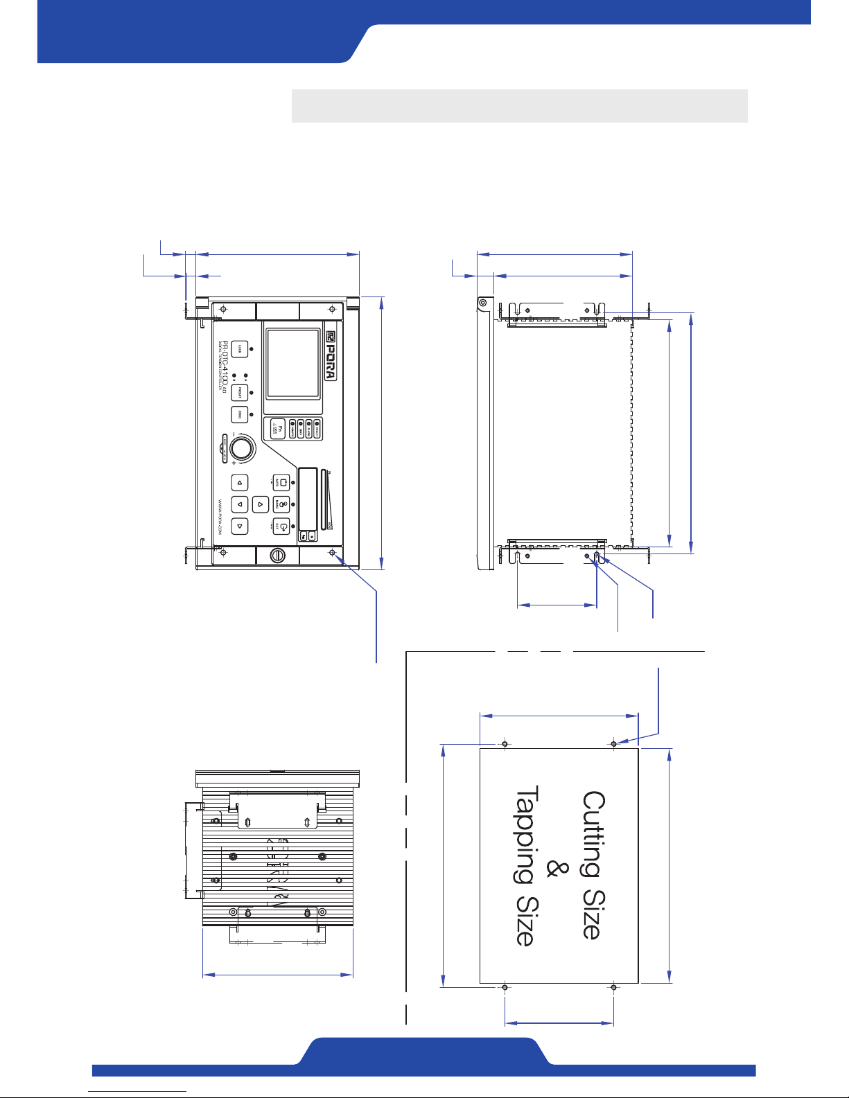
1. Dimensions
237
160
9.4
11
110
4-M5 Tap
246
276
4-Φ5 Hole
152
165
230
244
140
17
157
80
R2.1
M4 Tap
Before Use
Page 7
5
PORA ELECTRIC MACHINERY CO.,LTD.
PR-DTC-4100.A / AD
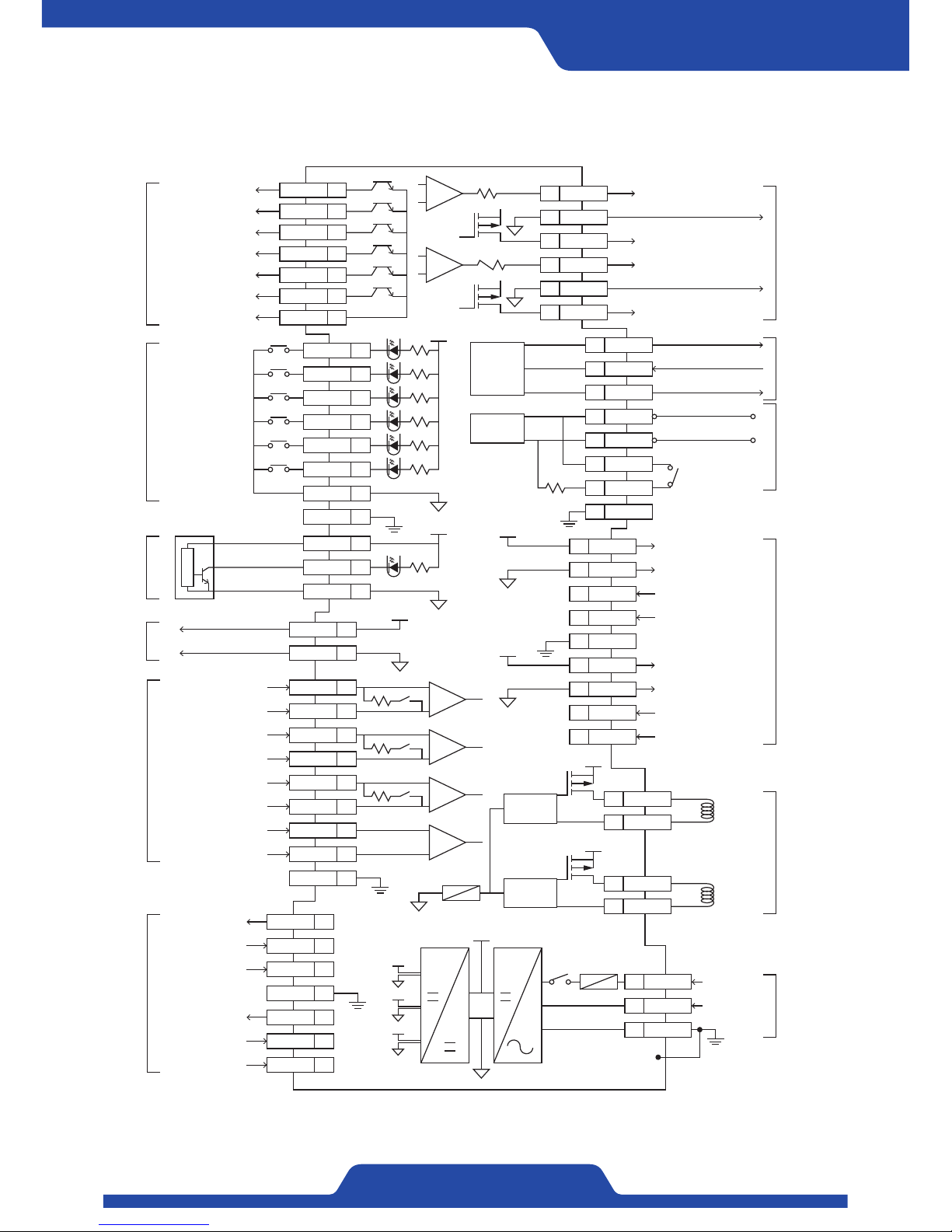
2. External connection diagram
DO1Digital output 1
Digital output 2
1
DO2 2
Digital output 3 DO3 3
Digital output 4 DO4 4
Digital output 5 DO5 5
Digital output 6 DO6 6
Digital output COM COM 7
+
-
+
-
+
-
249Ω
SW
249Ω
SW
249Ω
SW
+
-
AI1+Analog input 1+ 21
AI1-Analog input 1- 22
AI2+Analog input 2+ 23
AI2-Analog input 2- 24
AI3+Analog input 3+ 25
AI3-Analog input 3- 26
TG+TG input + 27
TG-TG input - 28
FG 29
Power for sensor PWM 30
Power for sensor PWM 34
Sensor input 3+ SIG3+ 31
Sensor input 4+ SIG4+ 35
Sensor input 4- SIG4- 36
Sensor input 3- SIG3- 32
FG 33
5V
+5V 19
GND 20
+
-
+
-
VO1 Voltage output for control37
IO1 Current output for control39
IO2 Current output for tension42
VO1 Voltage output for tension40
GND38
GND41
RS232
TX43
GND45
RX44
120Ω
CAN
Terminating
resistance
H46
L47
R148
R249
FG50
5V
5V
EXC1+ Power for sensor51
EXC2+ Power for sensor56
EXC2- Power for sensor57
EXC1- Power for sensor52
SIG1+ Sensor input 1+53
SIG1- Sensor input 1-54
FG55
SIG2+ Sensor input 2+58
SIG2- Sensor input 2-59
V+
V+
FUSE 7A
Driver A
Driver B
PA60
PB62
NA61
NB63
24Vdc/4.5A
24Vdc/4.5A
Only
PR-DTC-4100.AD
FUSE T1.6A
VCC
VEE
5V
V+
L Power65
N Power66
ANALOG
OUTPUT
RS-232
(Modbus-RTU)
CAN
SENSOR
INPUT1
POWDER
BRAKE
&
POWDER
CLUTCH
100~240Vac
FG64
METAL
PLATE
V+
V+
DI1 8
DI2 9
DI3 10
DI4 11
DI5 12
+24V
Power (24V)
Sensor signal
Ground
16
SIG 17
GND 18
DI6 13
COM 14
FG 15
Digital input 1
Digital input 2
Digital input 3
Digital input 4
Digital input 5
Digital input 6
Digital input COM
DIGITAL
OUTPUT
ANALOG
INPUT
SENSOR
INPUT2
(For
differential
pickup)
Power for
external
volume
DIGITAL
INPUT
PRX
Page 8
6
PORA ELECTRIC MACHINERY CO.,LTD.
Tension Controller
3. Product installation & Wiring
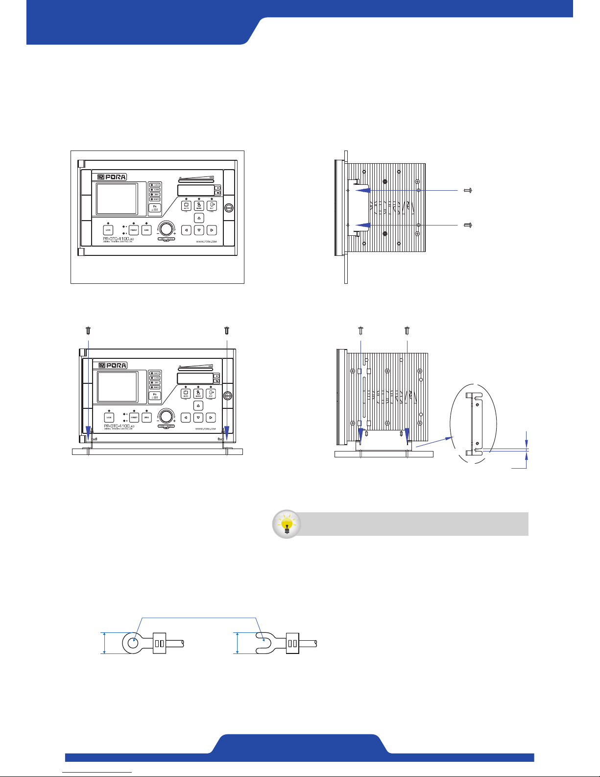
Combine a bracket with a main body and tighten a screw to fix the position a user hopes.
4.2
< Fixed type >
< Panel mount type >
1) How to install a controller
- Please use solderless terminal like same sized one of below image.
- Please tighten certainly not to cause malfunction.
- Input/output wiring should be wired through DUCT which is same as other power line and shouldn’t be tied
together.
NN
NN
.
2) Block arrangement
A controller can be installed with various way like below. Please install it where there is convenience and easy to
maintenance.
It is recommended to install the controller on a place where is
convenient to use and easy to maintain and repair.
Page 9
7
PORA ELECTRIC MACHINERY CO.,LTD.
PR-DTC-4100.A / AD
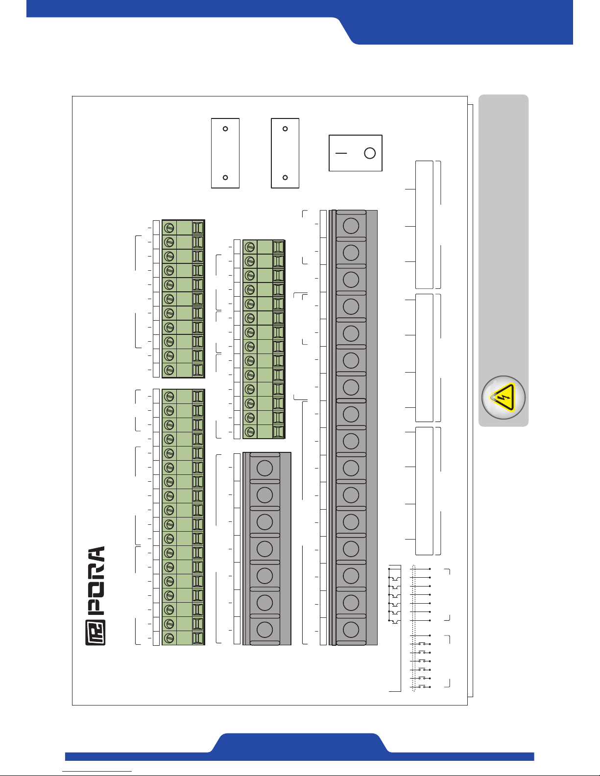
3) Terminal block
64 66656362616055 5756 595854535251
34 363533323130
www.pora.com
PR-DTC-4100.
A
/
PR-DTC-4100.
AD
DIGITAL TENSION CONTROLLER
(PRTL-A, PRTL-AB, PRTL-B, PRTL-C, PRTL-D, PRTL-E, PRTL-PA)
LOAD CELL TYPE
51 / 56 52 / 57 53 / 58 54 / 59
RED
(적색)
WHT
(흰색)
GRN
(녹색)
BLU
(청색)
SENSOR INPUT 1
51 / 56 52 / 57 53 / 58 54 / 59
(PR-LX-030TD, PR-LX-050TD, PR-100TD)
LVDT PICK UP TYPE
RED
(적색)
BLK
(흑색)
GRN
(녹색)
WHT
(흰색)
SENSOR INPUT 1
30 / 34 31 / 35 32 / 36
BRW
(갈색)
BLU
(청색)
GRN
(녹색)
(PRTP-2T, PRTP-3T, PRTP-5T)
DIFFERENTIAL PICK UP TYPE
SENSOR INPUT 2
19 20 21 22 23 2524 26 27 28 29
ANALOG INPUT
+5V GND AI1+ AI1- AI2+ AI3+AI2- AI3- TG+ TG- FG
13 14 15 16 17 188 9 1110 121 2 3 5 64 7
DO1 DI1 DI2 DI4DI3 DI5 DI6 COM FG +24V SIG GNDDO2 DO3 DO4 DO5 DO6 COM
DIGITAL OUTPUT DIGITAL INPUT PRX
30 31 32 34 3533 36
PWM SIG3+ SIG3- FG PWM SIG4+ SIG4-
SENSOR INPUT2
49 5044 45 4746 4837 38 39 41 4240 43
RX GND LH R1 R2 FGVO1 GND IO1 VO2 GND IO2 TX
RS232
(Modbus-RTU)
ANALOG OUTPUT CAN
60 61 62 64 6563 6651 52 53 5554 56 57 58 59
FG L NEXC1+ EXC1- SIG1+ SIG1- FG EXC2+ EXC2- SIG2+ SIG2-
SENSOR INPUT1 AC 100~240V
FUSE [ 1.6A ]
FUSE [ 7A ]
POWER S/W
DI1
8
DI2
9
DI3
10
DI4
11
DI5
12
DI6
13
COM
14
DIGITAL INPUT
DO1
1
DO2
2
DO3
3
DO4
4
DO5
5
DO6
6
COM
7
DIGITAL OUTPUT
PR-DTC-4100.AD ONLY
PA NA PB NB
POWDER BRAKE / POWDER CLUTCH
Faulty connecting of power block (Be careful about flow chart on the
power of normal load), contact DC input/output wiring with power wiring,
short circuit of output wiring, & etc. are major cause of severe damage.
Caution:
Checking power input & wiring
Page 10
8
PORA ELECTRIC MACHINERY CO.,LTD.
Tension Controller
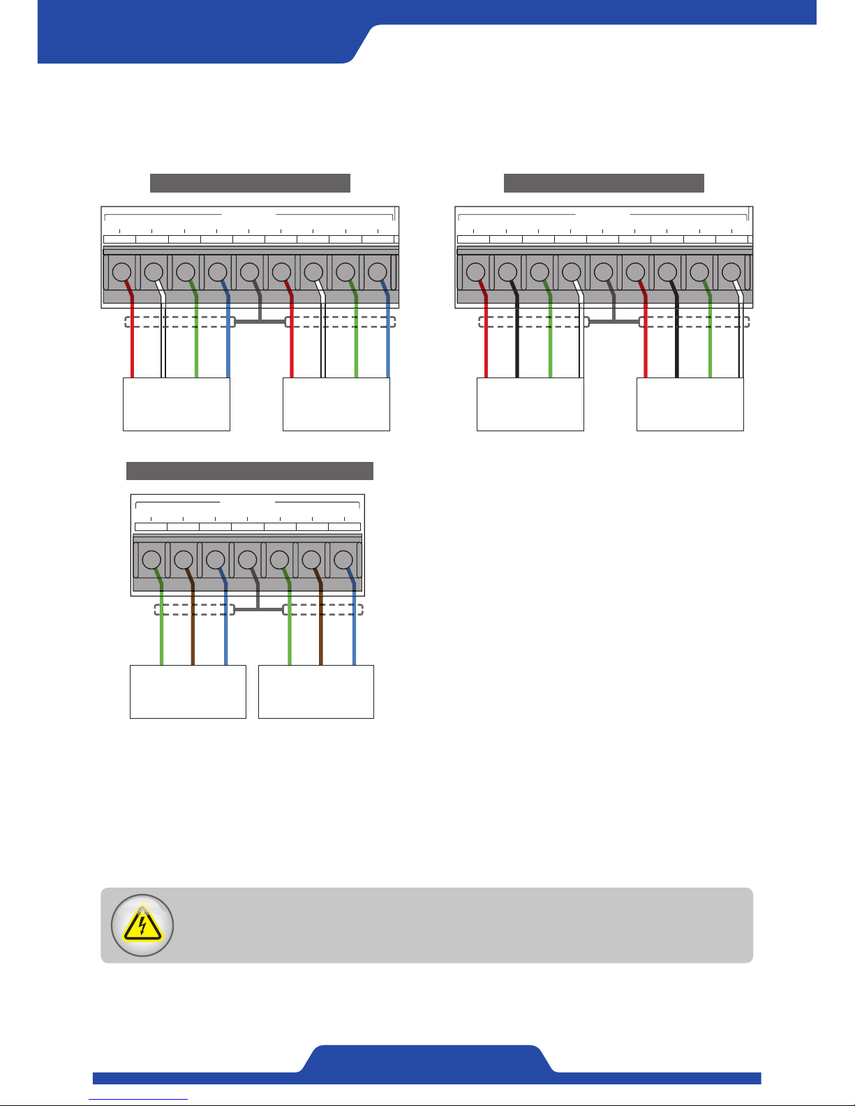
4) How to wire tension detector
Please connect accurately like below since the way of wiring is different according to the type of tension detector.
▶ PRTL (Loadcell): PRTL-A, PRTL-AB, PRTL-B, PRTL-C, PRTL-D, PRTL-E, PRTL-PA
▶ PR-LX (Pickup): PR-LX-030TD, PR-LX-050TD, PR-100TD
▶ PRTP (Differential pickup): PRTP-2T, PRTP-3T, PRTP-5T
64 666563626160
55 5756 595854535251
34 363533323130
www.pora.com
PR-DTC-4100.A / PR-DTC-4100.
AD
DIGITAL TENSION CONTROLLER
19 20 21 22 23 2524 26 27 28 29
ANALOG INPUT
+5V GND AI1+ AI1- AI2+ AI3+AI2- AI3- TG+ TG- FG
13 14 15 16 17 188 9 1110 121 2 3 5 64 7
DO1 DI1 DI2 DI4DI3 DI5 DI6 COM FG +24V SIG GNDDO2 DO3 DO4 DO5 DO6 COM
DIGITAL OUTPUT DIGITAL INPUT PRX
30 31 32 34 3533 36
PWM SIG3+ SIG3- FG PWM SIG4+ SIG4-
SENSOR INPUT2
49 5044 45 4746 4837 38 39 41 4240 43
RX GND LH R1 R2 FGVO1 GND IO1 VO2 GND IO2 TX
RS232
(Modbus-RTU)
ANALOG OUTPUT CAN
60 61 62 64 6563 66
51 52 53 5554 56 57 58 59
FG L N
EXC1+ EXC1- SIG1+ SIG1- FG EXC2+ EXC2- SIG2+ SIG2-
SENSOR INPUT1
AC 100~240V
FUSE [ 1.6A ]
FUSE [ 7A ]
PR-DTC-4100.AD ONLY
PA NA PB NB
POWDER BRAKE / POWDER CLUTCH
RED
WHITE
GREEN
BLUE
RED
WHITE
GREEN
BLUE
GROUND
Loadcell
(PRTL)
Sensor 1
Loadcell
(PRTL)
Sensor 2
Loadcell connection terminal
GREEN
GREEN
BROWN
BROWN
BLUE
BLUE
GROUND
34 363533323130
www.pora.com
PR-DTC-4100.A / PR-DTC-4100.
AD
DIGITAL TENSION CONTROLLER
19 20 21 22 23 2524 26 27 28 29
ANALOG INPUT
+5V GND AI1+ AI1- AI2+ AI3+AI2- AI3- TG+ TG- FG
13 14 15 16 17 188 9 1110 121 2 3 5 64 7
DO1 DI1 DI2 DI4DI3 DI5 DI6 COM FG +24V SIG GNDDO2 DO3 DO4 DO5 DO6 COM
DIGITAL OUTPUT DIGITAL INPUT PRX
30 31 32 34 3533 36
PWM SIG3+ SIG3- FG PWM SIG4+ SIG4-
SENSOR INPUT2
49 5044 45 4746 4837 38 39 41 4240 43
RX GND LH R1 R2 FGVO1 GND IO1 VO2 GND IO2 TX
RS232
(Modbus-RTU)
ANALOG OUTPUT CAN
FUSE [ 7A ]
Differential pickup
(PRTP)
Sensor 1
Differential pickup
(PRTP)
Sensor 2
Differential pickup connection terminal
RED
BLACK
GREEN
WHITE
RED
BLACK
GREEN
WHITE
GROUND
64 666563626160
55 5756 595854535251
34 363533323130
www.pora.com
PR-DTC-4100.A / PR-DTC-4100.
AD
DIGITAL TENSION CONTROLLER
19 20 21 22 23 2524 26 27 28 29
ANALOG INPUT
+5V GND AI1+ AI1- AI2+ AI3+AI2- AI3- TG+ TG- FG
13 14 15 16 17 188 9 1110 121 2 3 5 64 7
DO1 DI1 DI2 DI4DI3 DI5 DI6 COM FG +24V SIG GNDDO2 DO3 DO4 DO5 DO6 COM
DIGITAL OUTPUT DIGITAL INPUT PRX
30 31 32 34 3533 36
PWM SIG3+ SIG3- FG PWM SIG4+ SIG4-
SENSOR INPUT2
49 5044 45 4746 4837 38 39 41 4240 43
RX GND LH R1 R2 FGVO1 GND IO1 VO2 GND IO2 TX
RS232
(Modbus-RTU)
ANALOG OUTPUT CAN
60 61 62 64 6563 66
51 52 53 5554 56 57 58 59
FG L N
EXC1+ EXC1- SIG1+ SIG1- FG EXC2+ EXC2- SIG2+ SIG2-
SENSOR INPUT1
AC 100~240V
FUSE [ 1.6A ]
FUSE [ 7A ]
PR-DTC-4100.AD ONLY
PA NA PB NB
POWDER BRAKE / POWDER CLUTCH
Pickup
(PR-LX)
Sensor 1
Pickup
(PR-LX)
Sensor 2
Pickup connection terminal
The color of connection terminal between tension detector for pickup type and for loadcell type is different.
Please be sure to check the above connection terminal to avoid malfunction and damage.
Caution:
Please check each type of connection terminal for tension detector.
Page 11
9
PORA ELECTRIC MACHINERY CO.,LTD.
PR-DTC-4100.A / AD
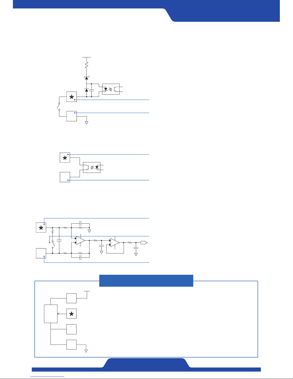
5) Digital input
Circuit for digital input is as the below. When using digital contact point, please make the volume of external
contact point right.
6) Digital output
Circuit for digital output is as the below. When using digital output contact point, please be sure not to overload
more than contact point volume.
7) Analog input
Analog input circuit is as below. Please be sure to check if the way of input which you hope to use at analog
input selection in setting menu is Voltage (0~10V) or Current (4~20mA).
When connecting potentiometer
In case of using by connecting potentiometer outside, please
arrange circuit as the below.
Please connect signal line of potentiometer to Al+ terminal
and Al- terminal to No.20 terminal (GND).
Please set the analog input at analog input section in setting
menu to be voltage (0~10V)
#
5V
5K
19
20
24V
24Vdc / 15mA
14
Terminal * shows each terminal number of
No. 8~13.
Terminal 14 is a common line of digital contact
point input.
24Vdc / 150mA
7
Terminal block * shows each terminal number of
No. 1~6.
Terminal 7 is a common line of digital contact point
output.
#
+
-
+
-
249Ω
SW
Terminal * shows Al+ (No. 21,23,25) block.
Terminal # shows Al- (No.22,24,26) block.
Internal SW runs according to the choice of
voltage or current. Please set accordingly to
the way of analog input signal.
Page 12
10
PORA ELECTRIC MACHINERY CO.,LTD.
Tension Controller
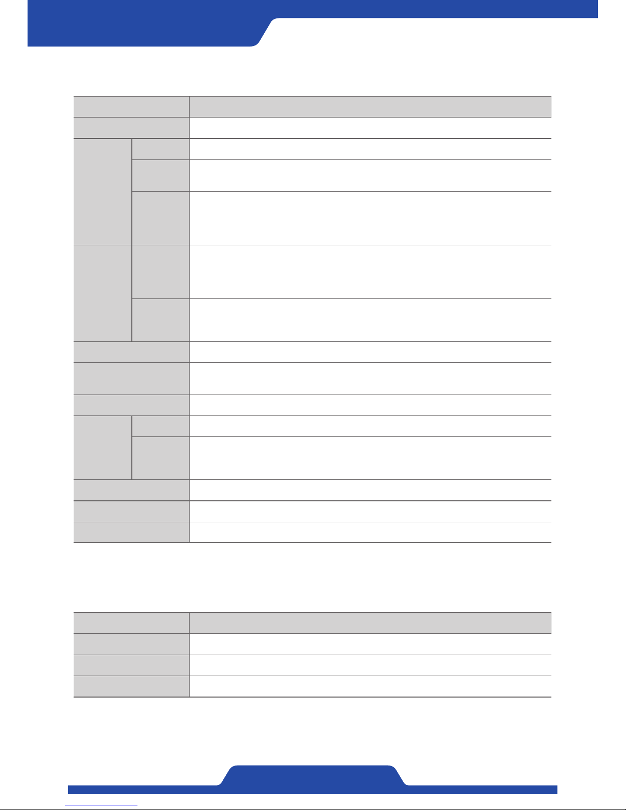
Item Specification
Display 3.2 inch Full Color TFT-LCD
Output
Control 0~24Vdc / 4.5A PWM type
Analog
Selectable between Control Output 0~10Vdc, -10~+10Vdc, 4~20mA, 0~20mA
Selectable between Tension Output 0~10Vdc, 4~20mA
Digital
6 Channels (24Vdc/150mA Open Collector)
Selectable between Auto, Manual, Output On, Tension Zero, Emergency Stop, Control
Shaft, The upper limit of control, the lower limit of control, Sensor error,
Tension error and Maximum diameter operation.
Input
Analog
3 channels (Selectable between 0~10Vdc, 4~20mA)
Selectable between target tension, manual output, line speed,
input diameter operation and dancer roll.
In case of using external volume, 2kΩ~10kΩ is recommended.
Digital
6 Channels (24Vdc/15mA)
Selectable between Auto, Manual, Output On, Tension Zero, Emergency Stop,
Shaft switch and initialization of operation diameter
Control Speed 5ms
Range of Tension
measurement
-9,999 ~ 99,999kg
Communication Hyper terminal (RS-232), Modbus-RTU (RS-232), Ethernet, CAN 2.0A
Power
Input 100~240Vac +/-10%, 50/60Hz (Single Phase)
Output
24Vdc / 0.5A Power for sensor pulse
5Vdc / 50mA Power for external volume
5Vdc / 1A Power for tension detector
Power consumption 120VA
Operation temperature 0℃~65℃
Weight 3kg
Sensor Model
PRTL (Load cell) PRTL-A, PRTL-AB, PRTL-B, PRTL-C, PRTL-D, PRTL-E, PRTL-PA
PR-LX (Pickup) PR-LX-030TD, PR-LX-050TD, PR-100TD
PRTP (Differential Pickup) PRTP-2T, PRTP-3T, PRTP-5T
5. Compatible Sensor
4. Product Specifications
※Besides, it is able to input tension detecting sensor ranging from 1mV/V~35mV/V.
Page 13
11
PORA ELECTRIC MACHINERY CO.,LTD.
PR-DTC-4100.A / AD
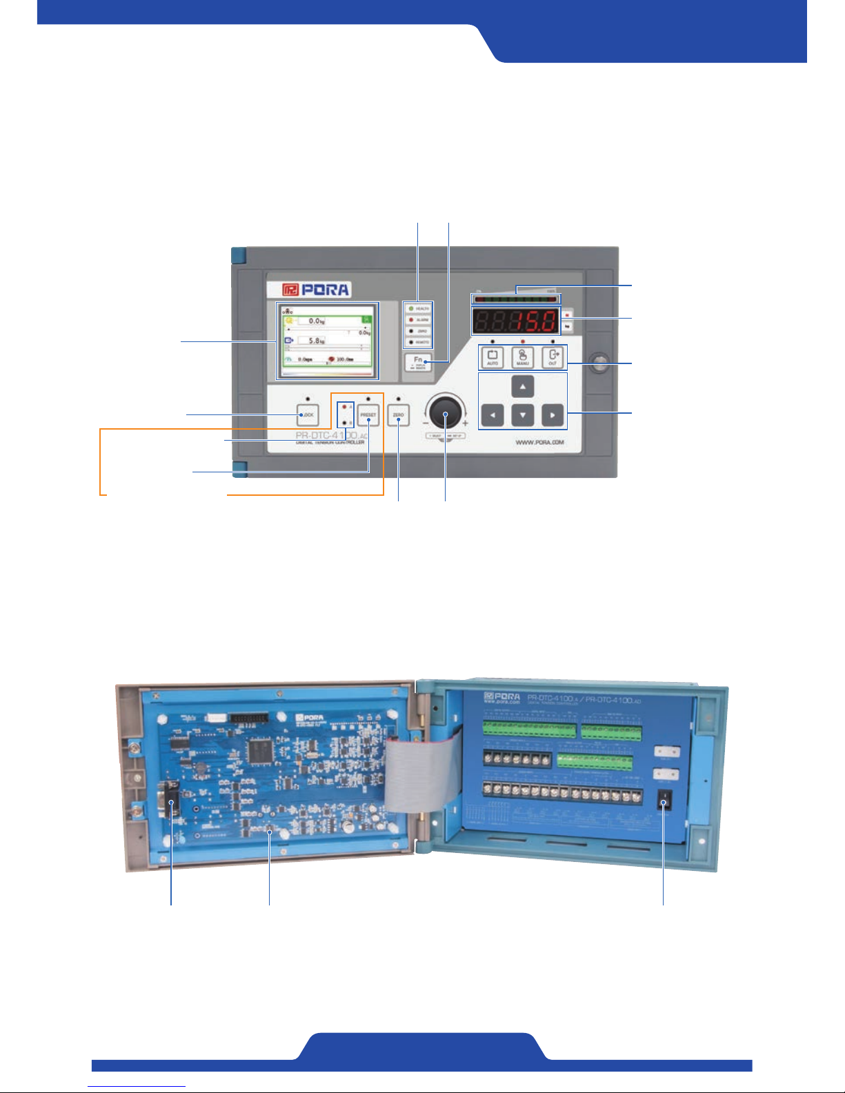
1) Front operating anel of PR-DTC-4100.AD
2) Operational Panel of Board side
6. Guidance on operating part
2. LED for indicating status 3. Fn Button
10. Dial button
4. LED for indicating
tension
5. FND for indicating
tension
9. Up/Down/Left/
Right button
6. Automatic button
7. Manual button
8. Output button
11. Zero button
12. Preset button
13. Indicating the status
of control shaft
14. Lock button
1. LCD Screen
16. Dip switch
17. Power switch15. Serial port
The limited function only for
PR-DTC-4100.AD
Page 14
12
PORA ELECTRIC MACHINERY CO.,LTD.
Tension Controller
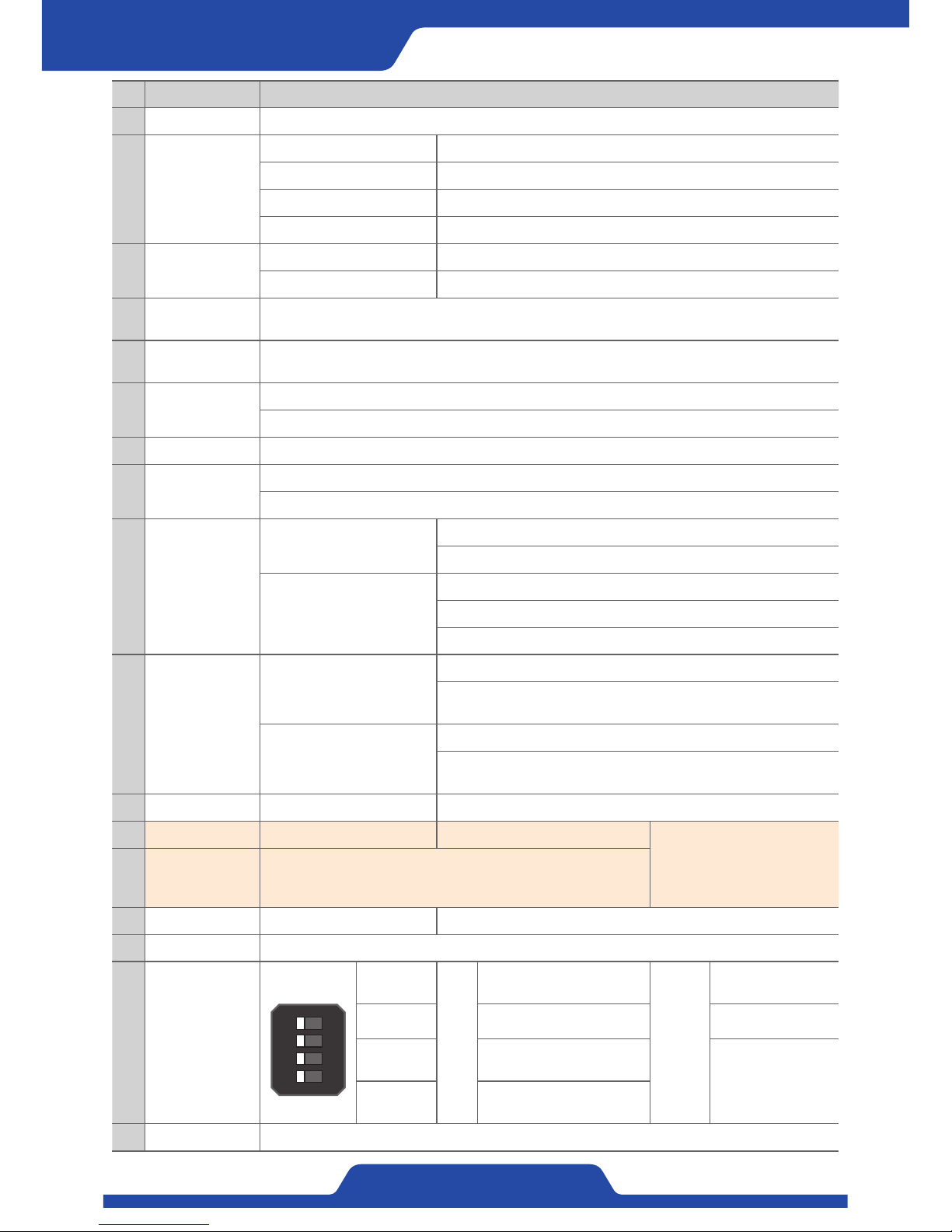
Title Guidance
1 LCD Screen It shows current status, values of data setting and output.
2
LED for indicating
status
HEALTH It becomes on when power status of a product is good.
ALARM It is on when alarm occurs.
ZERO It is on when zero tension value is 0.
REMOTE It is on when input contact point from external digital is being used.
3 Fn button
Input briefly It switches screen mode.
Input longer It vitalizes external digital (remote) input.
4
LED for indicating
tension
It shows current tension values based on an area before tension.
5
FND for indicating
tension
It shows tension values as kg or N (Selectable).
6 Automatic Button
It switches operation mode into automatic mode.
It operates as ESC button in setting mode, it is able to return to previous item or cancel.
7 Manual button It can switch operation mode to manual mode.
8 Output button
It sets status of output to On/Off.
It operates as [input button] in setting mode and it can choose an item and save setting values.
9
Up/Down/Left/
Right button
Up/Down button
In automatic mode, it adjusts values when setting P·I·D sensitivity.
It adjusts the range indicating tension at tendency graph display.
Left/Right Button
It adjusts Time/Div at tendency graph screen.
In automatic mode, it shifts an item when setting P·I·D sensitivity.
In setting mode, it shifts a screen, an item and a cipher of setting values.
10 Dial button
Input briefly
In every kind of mode, it operates as [ENTER button].
Auto/Manual mode: It shifts a setting item
(Target tension, Manual output).
Input longer
Manual mode: It enters to setting mode.
Automatic mode: It enters to the mode of P·I·D sensitivity adjustment.
(When it is possible to P·I·D setting.
11 Zero button Input longer It adjusts current tension values to be zero.
12 Preset button Input longer Control shaft (A/B) is switched.
※ The limited function only for
PR-DTC-4100.AD
13
Indicating the
status of control
shaft
It indicates current status of control shaft as LED.
14 Lock button Input longer It vitalizes button lock function.
15 Serial port It is used for product firmware upgrade.
16 Dip switch
1
2
3
4
ONOFF
1. CALI
ON
/
OFF
Selectable P·I·D setting
while on operation.
Remark
-
- - -
3. Ethernet
Setting Ethernet
communication.
When Ethernet, all
Modbus dip switches
are on, it is set to
Modbus use.
4. Modbus
Modbus Modbus-RTU
Communication setting.
17 Power switch It turns on or off the power.
Page 15
13
PORA ELECTRIC MACHINERY CO.,LTD.
PR-DTC-4100.A / AD
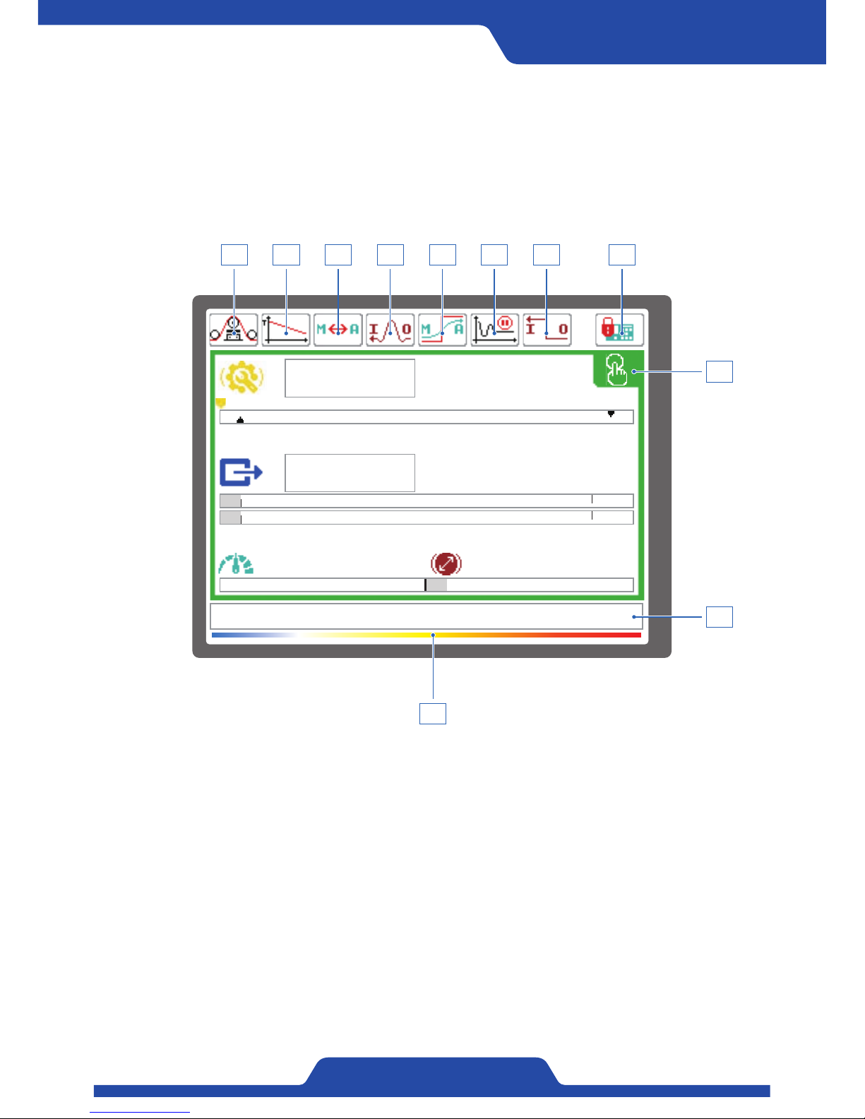
7. Guidance on Display
/ (Display change with Fn Button)
Guidance on Icon and screen
0.0kg
0.0kg
0.0mpm 100.0mm
T
5.8%
~
1 3 4 5
11
6 7 8
9
10
2
※NOTE: The order of setting icon may change depending on whether to use or not set-up function.
Page 16
14
PORA ELECTRIC MACHINERY CO.,LTD.
Tension Controller
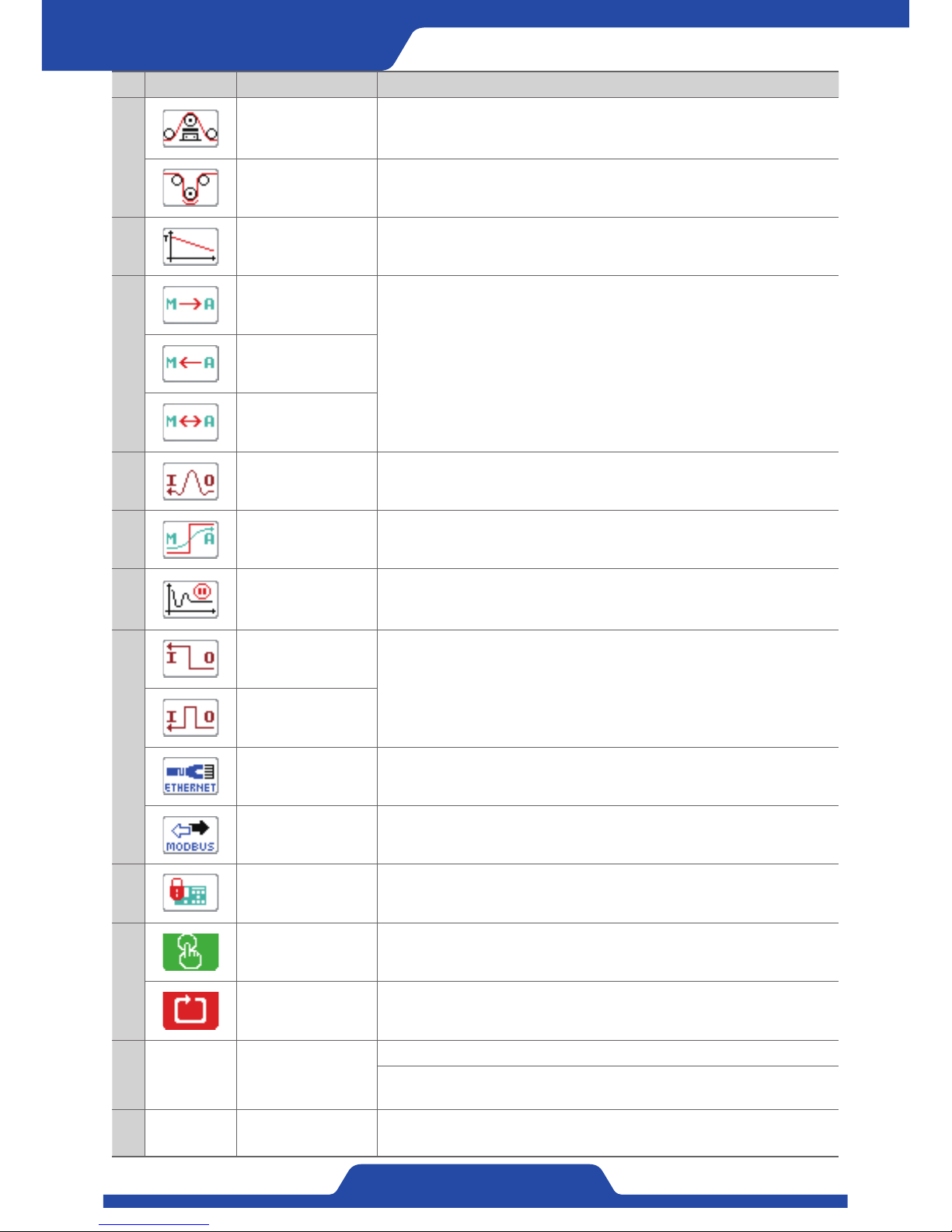
Icon Name Guidance
1
PRTL
PRLX
PRTP
●
It is shown when setting a sensor (tension detector).
- PRTL: Loadcell, PRLX: Pickup, PRTP: Differential pickup
DANCER ROLL It is shown when setting dancer roll.
2
Taper function It is shown when setting taper.
3
M/A CHANGE
MANU-->AUTO
It is shown when setting Manu/Auto interlock.
M/A CHANGE
MANU<--AUTO
M/A CHANGE
MANU<->AUTO
4
Using analog input It is shown when setting analog input.
5
Switching
Manu/Auto mode
It is shown when setting Auto/Manu mode switch.
6
Using output
maintenance
function
It is shown when setting output maintenance function.
7
Hold
It is shown the way of digital input signal chosen.
Pulse
Ethernet It is shown when setting Ethernet communication.
Modbus It is shown when setting Modbus communication.
8
Using lock function It is shown when setting lock function of operating part and dial.
9
Using manual mode It is shown when using manual mode.
Using Automatic
mode
It is shown when using automatic mode.
10 - Alarm
It shows the contents on specific operating status.
Key lock, Zero setting, Using remote, Remote unused, Faulty power,
Overheating, Overload A, Overload B
11 -
Indicating product
temperature
It shows temperature of drive board.
Page 17
15
PORA ELECTRIC MACHINERY CO.,LTD.
PR-DTC-4100.A / AD
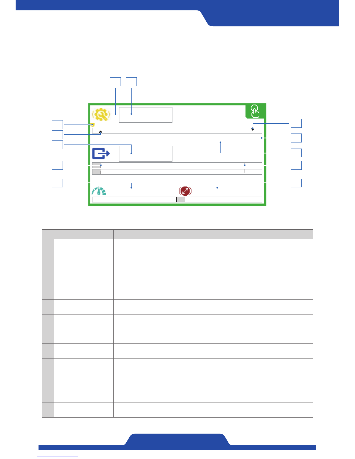
1) Type 1 (Bar graph display): It shows tension values, output values, operation
diameter and line speed as the shape of bar
graph.
0.0kg
0.0kg
0.0mpm 100.0mm
T
5.8%
~
3
9
10
6
12
4
5
8
11 12
7
Name Guidance
1 Target tension It shows set-up target tension.
2 Using analog input
When using ‘Analog input’, a wave dash ( ~ ) is shown.
(In case that ~ (Wave dash) is shown, the dial button at front part does not work.)
3 Target tension arrow The position of target tension is indicated as an arrow.
4 Lower limit of tension It shows set-up lower limit of tension.
5 Upper limit of tension It shows set-up upper limit of tension.
6 Measured tension It shows currently measured tension.
7 Indicating tension Tension total (T), Left (L), Right (R)
8 Control output It shows values of control output.
9 Excitation voltage It shows set-up excitation voltage.
10 Output limit It shows set-up output limit.
11 Line speed It shows line speed.
12 Diameter operation It shows current diameter operation.
Page 18
16
PORA ELECTRIC MACHINERY CO.,LTD.
Tension Controller
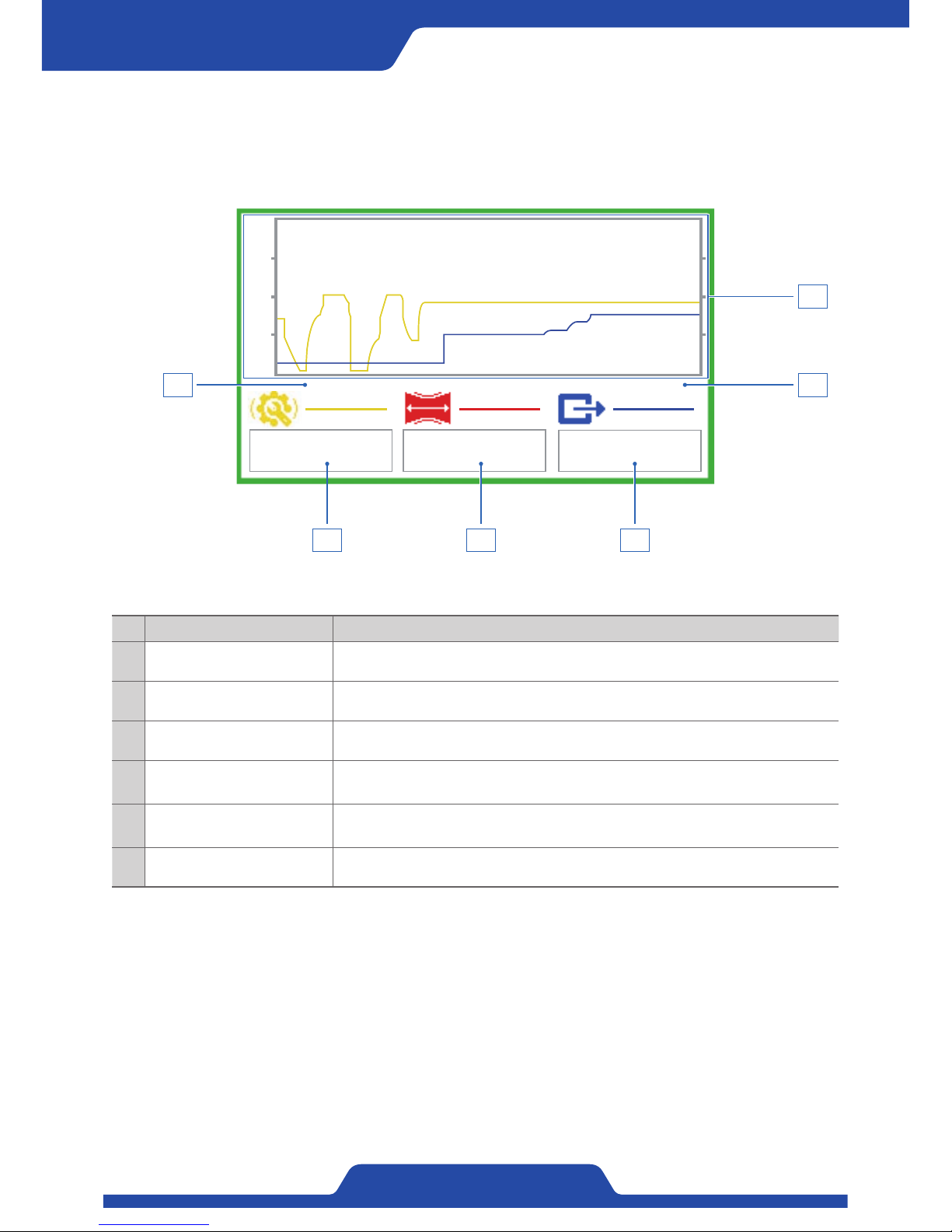
2) Type 2 (Tendency graph display): It is able to watch a change of tension
values, output values, target values
through tendency graph.
Name Guidance
1 Target tension It shows set-up target tension being by a user.
2 Measured tension It shows currently measured tension.
3 Controlled output It shows values of control output.
4 Graph display
It shows target tension, measured tension, and values of control output as a
shape of tendency graph.
5 Time setting
It is able to set the movement speed of a graph using left/right button.
(Time/Div)
6 Tension setting It is able to set the range of tension indicated using up/down button.
4.5kg 18.2kg
38.4%
◀ 0.05s ▶▲ 10kg ▼
0
50
100
1 2 3
56
4
Page 19
17
PORA ELECTRIC MACHINERY CO.,LTD.
PR-DTC-4100.A / AD
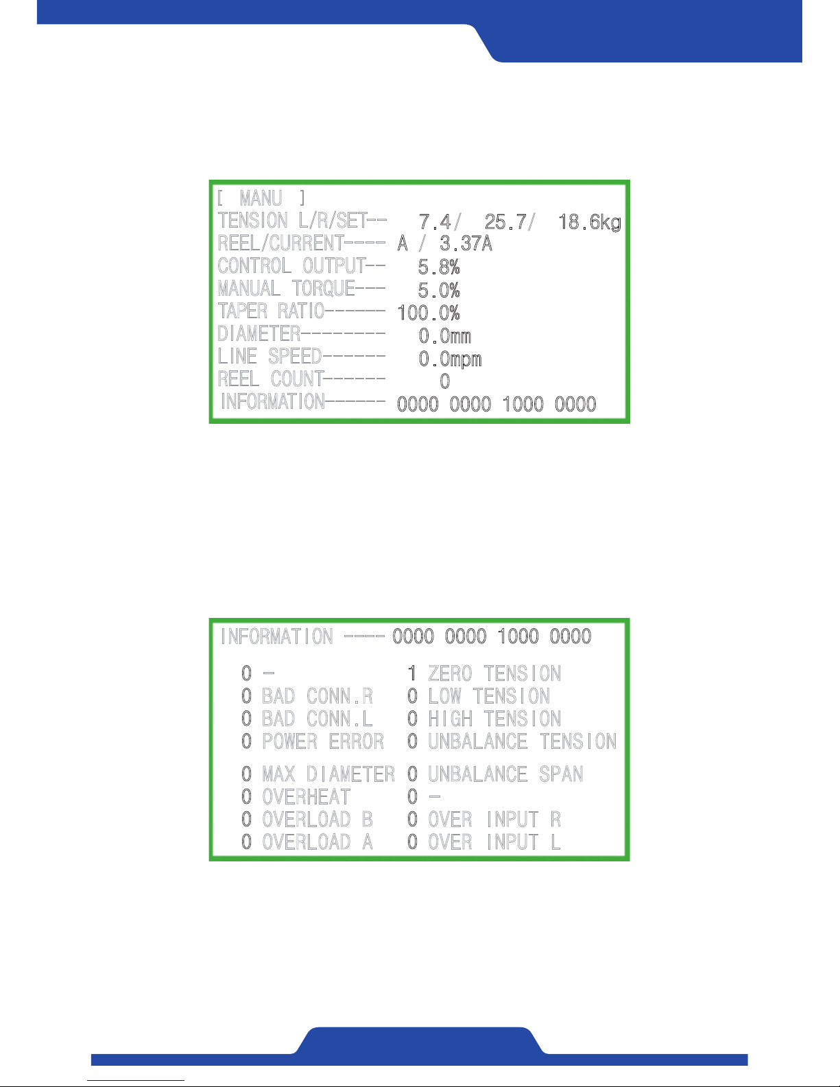
3) Type 3 (Data display): It shows standard setting values and the information
of current operation as a shape of data figures.
[ ]
MANU
TENSION L/R/SET-REEL/CURRENT---CONTROL OUTPUT-MANUAL TORQUE--TAPER RATIO-----DIAMETER-------LINE SPEED-----REEL COUNT-----INFORMATION------
/
7.4
/
100.0%
0.0mm
0.0mpm
0
0000 0000 1000 0000
5.8%
5.0%
A 3.37A
/
25.7 18.6kg
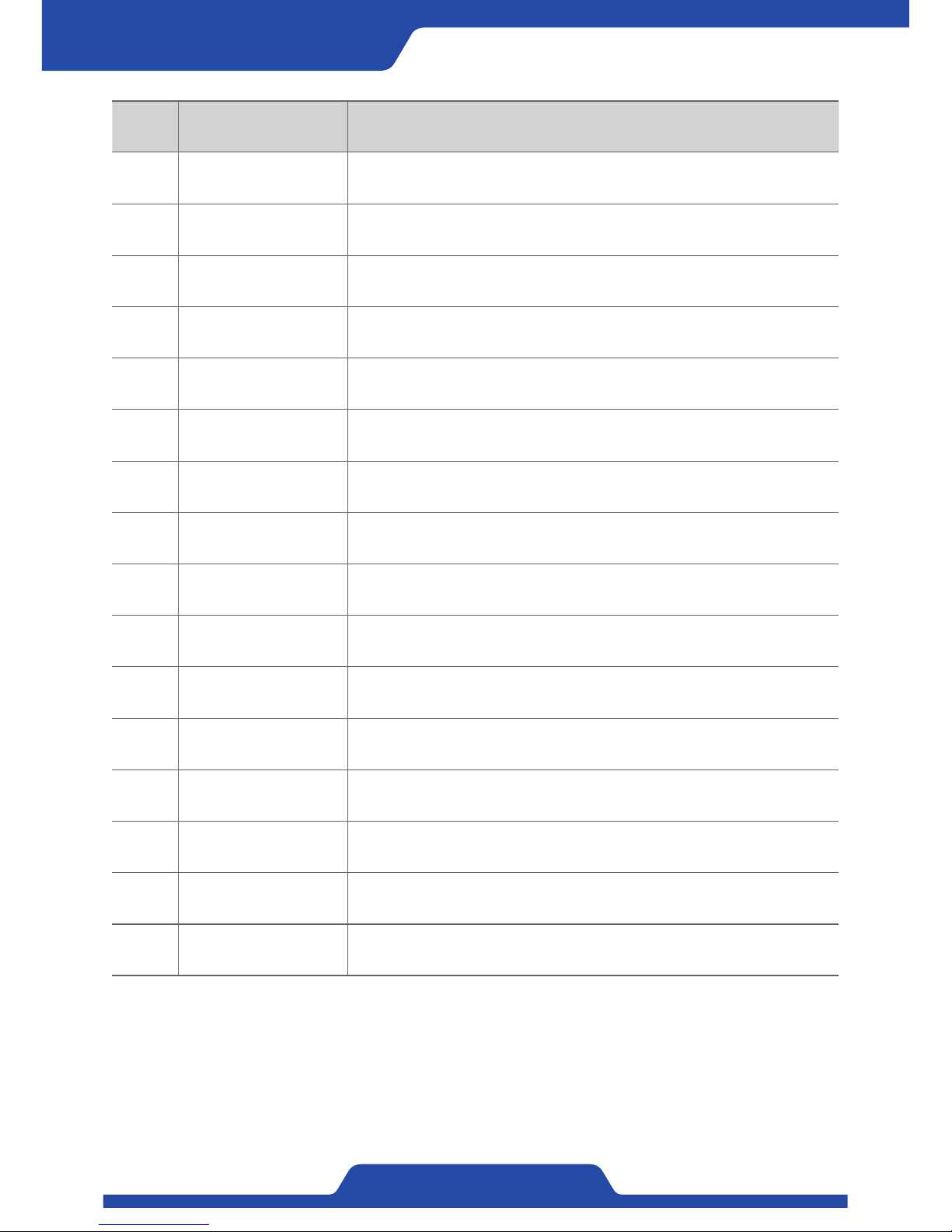
4) Alarm message display: When pressing Left/right button longer together
in data display, it is able to check message
information.
0 - 1 ZERO TENSION
0 BAD CONN.R 0 LOW TENSION
0 BAD CONN.L 0 HIGH TENSION
0 POWER ERROR 0 UNBALANCE TENSION
0 MAX DIAMETER 0 UNBALANCE SPAN
0 OVERHEAT 0 0 OVERLOAD B 0 OVER INPUT R
0 OVERLOAD A 0 OVER INPUT L
INFORMATION ---- 0000 0000 1000 0000
15 7
8 0
Bit: 15 8 07
Page 20
18
PORA ELECTRIC MACHINERY CO.,LTD.
Tension Controller
Alarm bit Alarm contents Detailed explanation
0 OVER INPUT L Input signal of left tension detector has exceeded the standard.
1 OVER INPUT R Input signal of right tension detector has exceeded the standard.
2 - -
3 UNBALANCE SPAN Left/right span values are imbalance more than 20%.
4 UNBALANCE TENSION Left/right tension values are imbalance more than 20%.
5 HIGH TENSION Tension values goes up more than upper limit of setting values.
6 LOW TENSION Tension values goes down less than lower limit of setting values
7 ZERO TENSION Tension value is 0kg.
8 OVERLOAD A Overload has occurred to A output of control shaft.
9 OVERLOAD B Overload has occurred to B output of control shaft.
10 OVERHEAT The driver board inside a product is overheating (more than 70℃ )
11 MAX DIAMETER Diameter operation has reached maximum values.
12 POWER ERROR The power (+12V, +12V, 5V) inside a product is unstable.
13 BAD CONN . L An error has occurred to wiring of left tension detector signal.
14 BAD CONN . R An error has occurred to wiring of right tension detector signal.
15 - -
Page 21
19
PORA ELECTRIC MACHINERY CO.,LTD.
PR-DTC-4100.A / AD
Working & Operation
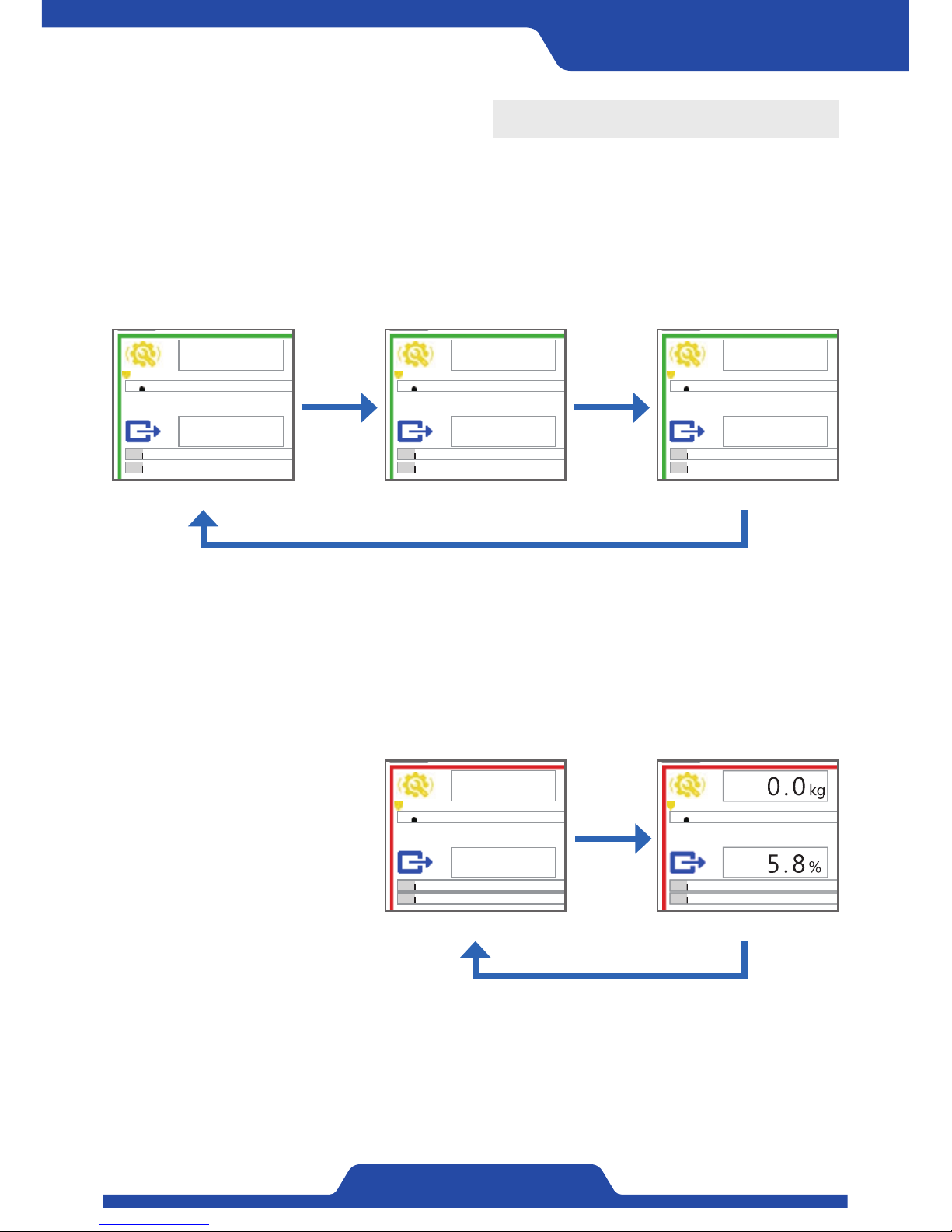
- When pressing [Manual button] in automatic mode, it switches to manual mode.
- Figures of manual output become activated, it is able to set manual output values using [Dial].
- Whenever pressing [Dial button], setting data becomes activated.
1. Manual/Automatic mode
1) Manual Mode
0.0kg
0.0kg
T
5.8%
0.0kg
0.0kg
T
5.8%
0.0kg
0.0kg
T
5.8%
[ Setting impossible ]
Pressing
dial
Pressing dial
[ Setting impossible ]
Pressing dial
Pressing
dial
[ Possible to set manual output ] [ Possible to set target tension ]
- When pressing [Automatic button] in manual mode, it switches to automatic mode.
- Figures of target tension become activated, it is able to set target tension values using [Dial].
- Whenever pressing [Dial button], setting data becomes activated.
0.0kg
0.0kg
T
5.8%
0.0kg
0.0kg
T
5.8%
[ Possible to set target tension ]
2) Automatic mode
Pressing
dial
Page 22
20
PORA ELECTRIC MACHINERY CO.,LTD.
Tension Controller
1) When pressing [zero button] longer in manual or automatic mode,
current tension becomes zero.
2) At this time, LED at the top of [zero button] starts to work.
3) It is able to also set zero by using digital input contact point.
4) In case of dancer roll, please set zero by fixing to the position (the
lowest limit of dancer roll) where tension is lowest.
2. Setting zero
※ To carry out setting zero, please remove materials on the top of the roller where tension detector is installed at
first.
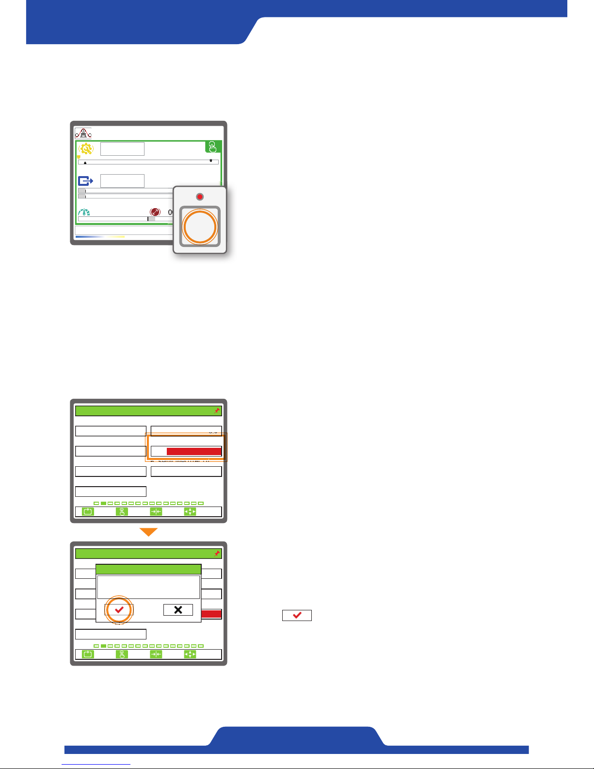
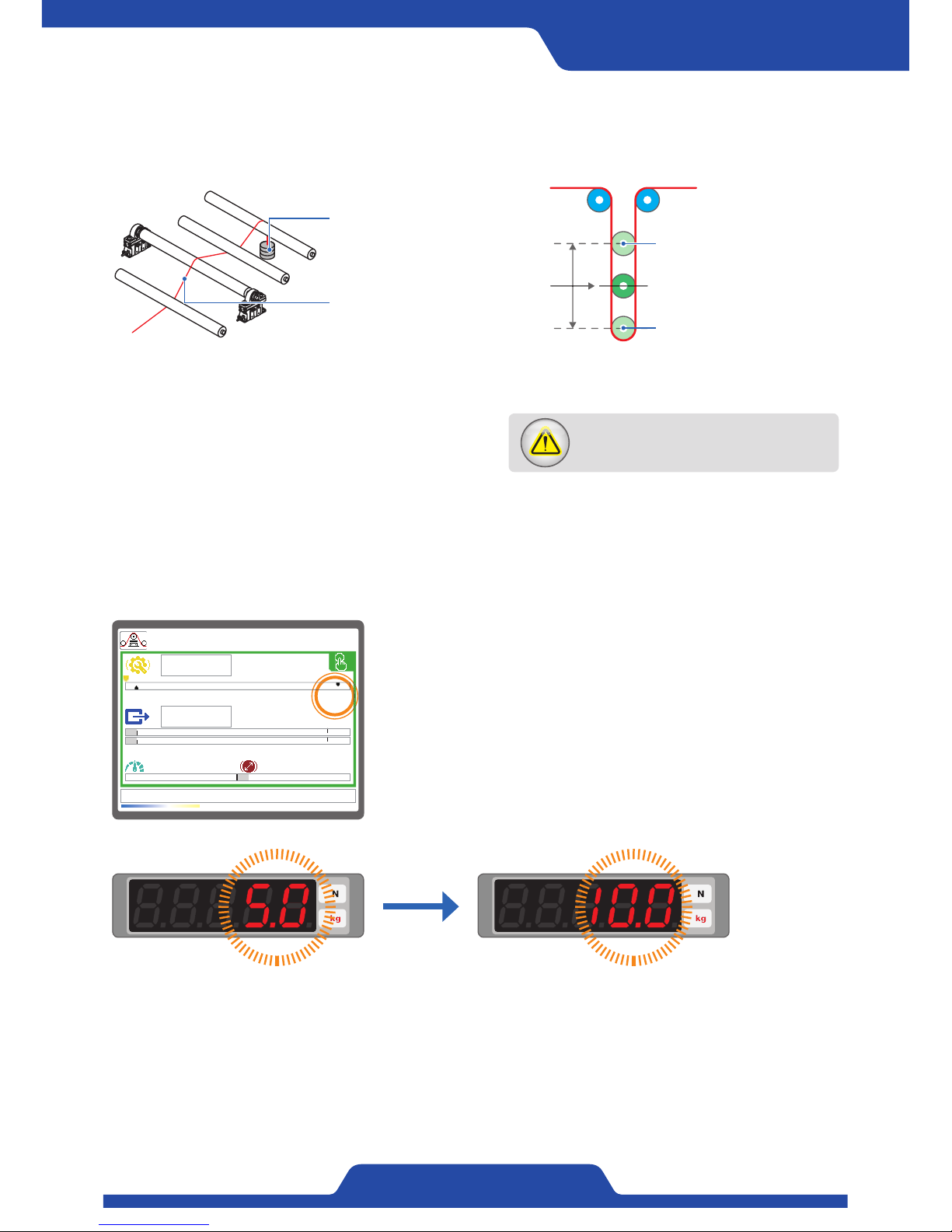
1) Please set [4. CAL. TENSION]. The value of tension calibration is as
much as the load applied to a roller.
( Setting mode -> 2. TENSION CALIBRATION -> [4. CAL. TENSION] ->
Entering the value of calibrated tension values.)
3. Span Setting
※ Please complete zero setting point at first before span setting and adapt the angle of materials at the top of
roller where tension detector is installed and then apply load. For smooth tension detecting, precise span
setting should be done.
2) Activate [6. SPAN INPUT(BCD)] to complete span setting by entering
current data.
(Setting mode -> 2. TENSION CALIBRATION -> Activating an article
by pressing [Enter button] in [6. SPAN INPUT(BCD)] -> Pressing a
button ( ) to complete span setting.)
3) In case of dancer roll, please set span by fixing to the position (the
upper limit of dancer roll) where tension is maximum.
0.0kg
0.0kg
0.0mpm 100.0mm
T
5.8%
~
Tension zero!
ZERO
ESC CLR SET
SELECT
1. SENSOR SELECT 2. SENSOR SIG(mV/V)
3. FULL SCALE(kg, N) 4. CAL. TENSION(kg, N)
5. ZERO INPUT(BCD) 6. SPAN INPUT(BCD)
100
PRTL
4095/ 40950/ 0
7. CALI. SCALE(%)
100.0
3.0
2. TENSION CALIBRATION
30
ESC CLR SET
SELECT
1. SENSOR SELECT 2. SENSOR SIG(mV/V)
3. FULL SCALE(kg, N) 4. CAL. TENSION(kg, N)
5. ZERO INPUT(BCD) 6. SPAN INPUT(BCD)
100
PRTL
0/ 0
7. CALI. SCALE(%)
100.0
3.0
30
2. TENSION CALIBRATION
4095/ 4095
Curr. 4095/ 4095
6. SPAN INPUT(BCD)
-150/ -150
Page 23
21
PORA ELECTRIC MACHINERY CO.,LTD.
PR-DTC-4100.A / AD
If an error occurs and materials or a weight
is hung, please get rid of all and start from
first.
Span setting of tension detector: The load of tension detector by tension of materials changes depending on the
way where a detector is installed or the load angle of materials. To calibrate it, please proceed span setting.
(※ Please install a counterweight whose the maximum load of a tension detector is 30~100% to a roller like below. For example, In
case that the maximum load of a tension detector is 100kg, select a counterweight which is 30~100kg.)
[ In case of dancer roll ][ In case of load cell ]
Counterweight:
30~100% weight of the
maximum load from a
tension detector.
The upper part of dancer roll
(Position to set span)
The lower part of dancer roll
(Position to set zero)
Please let a string which
has a counterweight for
the upper limit of dancer
roll (Span setting location)
pass trough in the middle
of roller like an image.
Please be sure for a
string not to pass though
below a roller where
a tension detector is
installed.
1) In manual or automatic mode, when pressing [Up/down button] at
the same time, it gets to enter scale setting mode.
2) Tension values on display becomes red color, figures indicating
tension in FND starts to flicker. At this time, adjust figures of tension
using [Dial button].
3) After complete calibration, exit scale setting mode with pressing [Up/
down button] together longer.
4. Tension calibration (Scale setting)
※ If it is not possible to span setting depending on circumstances or a user just knows the materials of tension at
a guess, it is able to calibrate tension by setting scale.
0.0kg
5.0kg
0.0mpm 100.0mm
T
5.8%
~
100%0%
100%0%
Dial
Page 24
22
PORA ELECTRIC MACHINERY CO.,LTD.
Tension Controller
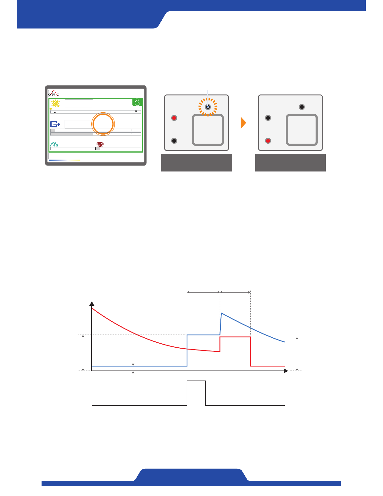
1) In automatic or manual mode, when pressing [Preset button] on front panel longer, it starts to enter shaft switch
mode.
2) During waiting time, a shaft which will be switched generates waiting output, LED on the upper of button
flickers. After completing shaft switch, previous shaft generates waiting output during finish time and LED on the
upper of button flickers again.
3) In addition, it is possible to switch shaft using digital input contact point or communication.
5. A, B Output switch
※This A, B output switch function is available only for PR-DTC-4100.AD. Please be reminded.
※ When switching A, B control shaft, it may need waiting time and waiting output. Please check in advance if the
setting is well.
0.0kg
0.0kg
0.0mpm 100.0mm
T
CHANGE
5.0
5.8%
~
PRESET
B
A
PRESET
B
A
LED flickered during the time of output switch
In the middle of shaft
switching A-> B control
Complete to switch
B control shaft
[B] Waiting
output
Excitation voltage
Waiting time
of shaft switch
Finish time
of shaft switch
PRESET ON OFF
B
A
[A] Waiting
output
Page 25
23
PORA ELECTRIC MACHINERY CO.,LTD.
PR-DTC-4100.A / AD
6. P·I·D Sensitivity setting
※P·I·D needs to be adjusted when control output in automatic mode responds too fast or too late.
※ Before setting, [Possible to set P·I·D while in operation] at first article of the Dip switch from board side
should be ON. (Refer to page 11~12.)
0.0kg
0.0kg
0.0mpm 100.0mm
T
5.8%
~
[PID SET] P: 2.0% I: 1.0% D: 0.1%
1) When pressing [Dial button] longer in automatic mode, it gets to
enter P·I·D setting mode.
2) P·I·D sensitivity figures will be shown at the below of a display.
3) Please adjust figures of each sensitivity using [Up/down/left/right
button] with checking the reacting condition of control output.
4) If the adjustment is done, press [Dial button] longer to exit P·I·D
sensitivity setting mode.
5) After setting is completed, please OFF at first article of a Dip switch
from board side.
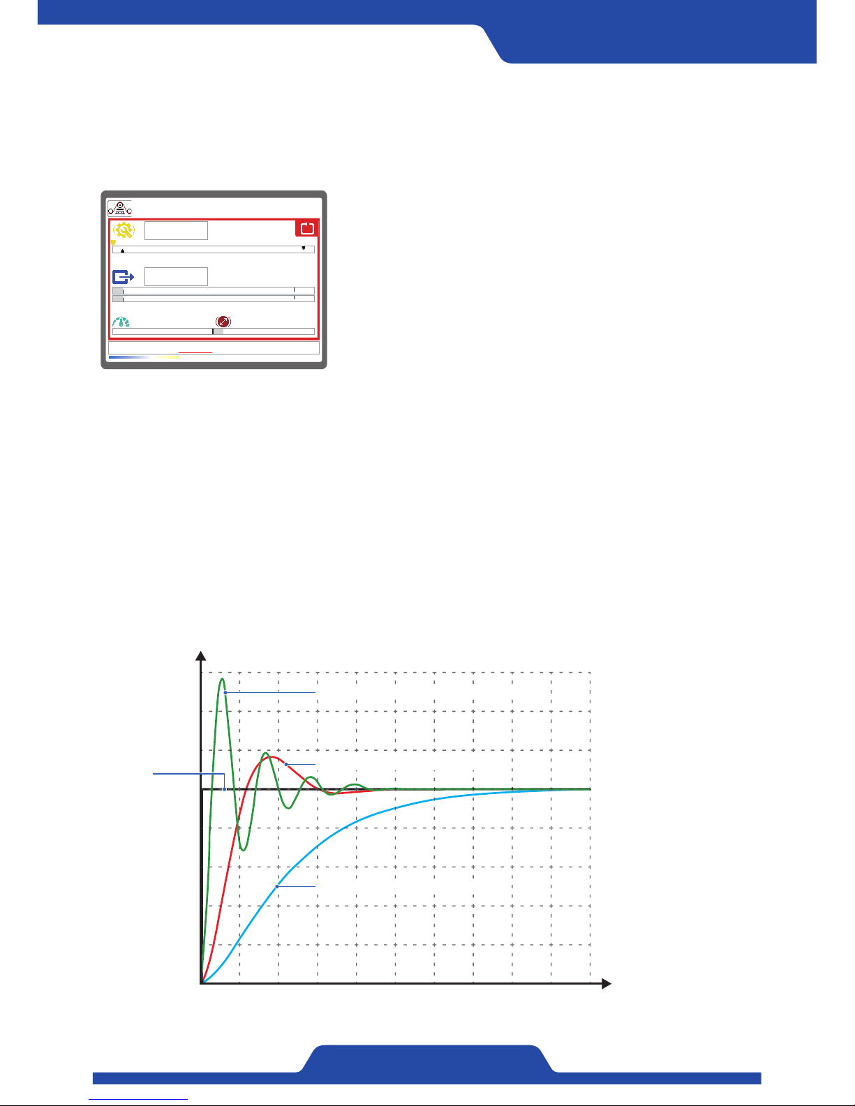
- P Control (Proportional control: Gain)
It generates control output which is proportionate to tension error. It can control stably than ON/OFF control and
can decrease the time to reach target value but there is always a normal state error (An error between actual
tension and target tension).
- I Control (Integral control: Stability)
To get rid of a normal state error, it reflects control output by accumulating tension error. The less the setting
values are, it can secure stability, however it will take much time to reach target value. So it needs to adjust
appropriate figure.
- D Control (Differential control: Response)
It reflects control output by setting the change of tension error to set an error value. It puts on the brakes sudden
change to decrease overshoot and improve stability.
0.2
0.4
0.6
0.8
1
1.2
1.4
1.6
Tension
(kg)
0 2 4 6 8 10 12 14 16 18 20 Time (sec)
Very fast response and poor stability
Easy stability and medium speed
Very stable but late response
Set
point
※NOTE
Please set within the range which is not much different from the factory setting value.
Page 26
24
PORA ELECTRIC MACHINERY CO.,LTD.
Tension Controller
7. Button lock function
※ If using this button lock function of a controller, it can prevent mal-operation by carelessness of a user in
advance.
0.0kg
0.0kg
0.0mpm 100.0mm
T
5.8%
~
[ Lock button ]
LOCK
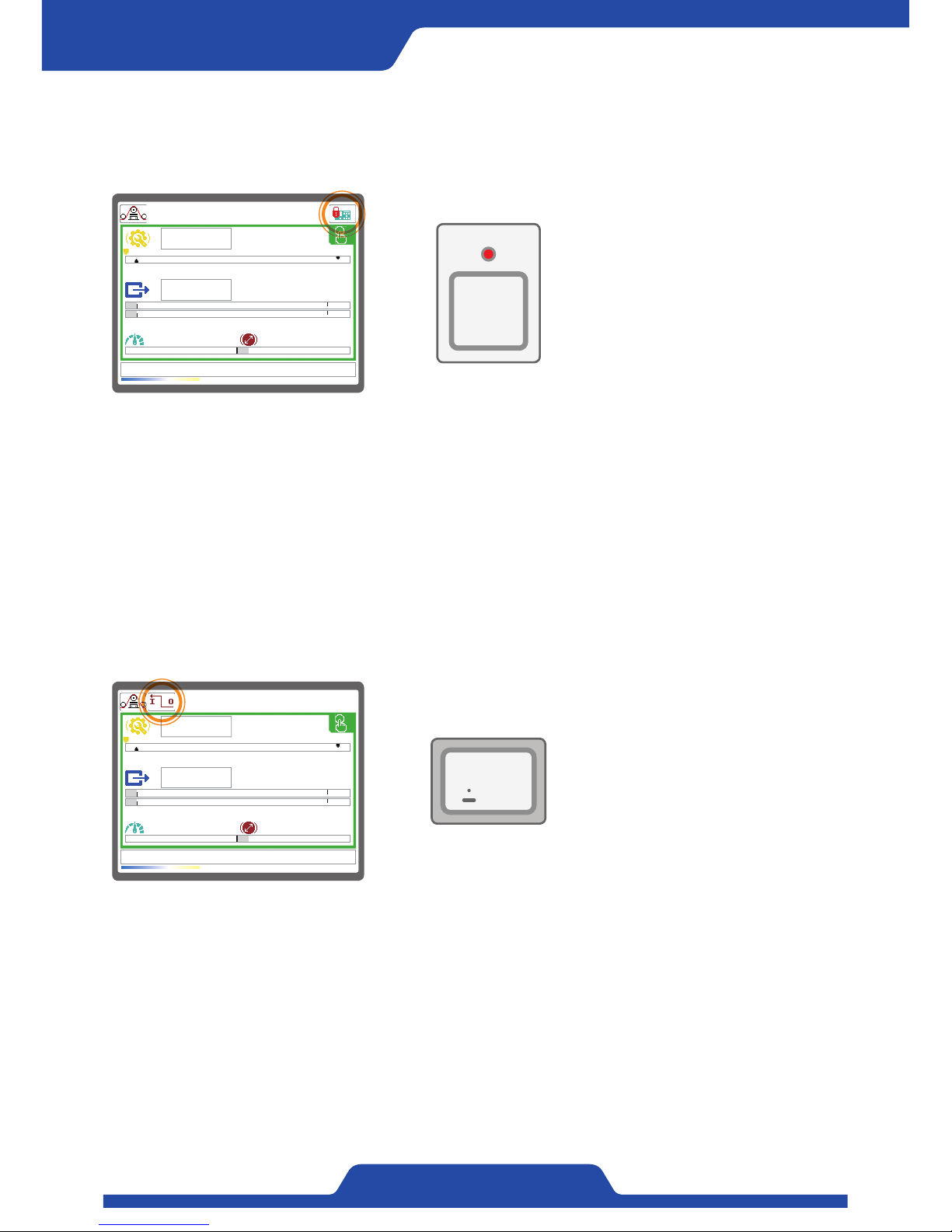
1) When pressing [Lock button] longer in automatic mode or manual mode, button lock function vitalizes and the
button does not work. (Only lock button works)
2) LED at the upper of [Lock button] is on, lock icon will be shown on a display.
3) When pressing [Lock button] longer again while lock function is working, it is unlocked.
8. Remote function
※ When hoping to control a controller using digital contact point or communication from outside, please use this
function.
0.0kg
0.0kg
0.0mpm 100.0mm
T
OFF
~
Remote activated!
[ Fn button ]
1) When pressing [Fn button] longer at front operational part in automatic or manual mode, remote function starts
to work. Remote LED is on and an Icon for remote contact point is shown on a screen.
2) A button of a controller can not be read depending on the way of setting of digital input contact point.
3) When pressing [Fn button] longer again, remote function does not work.
4) When using communication function except for hyper terminal, remote function has to be activated.
(When using communication, digital input is not read.)
5) It is always able to set remote function to be working when turning the powder using initial operation mode
function.
Fn
DISPLAY
REMOTE
Page 27
25
PORA ELECTRIC MACHINERY CO.,LTD.
PR-DTC-4100.A / AD
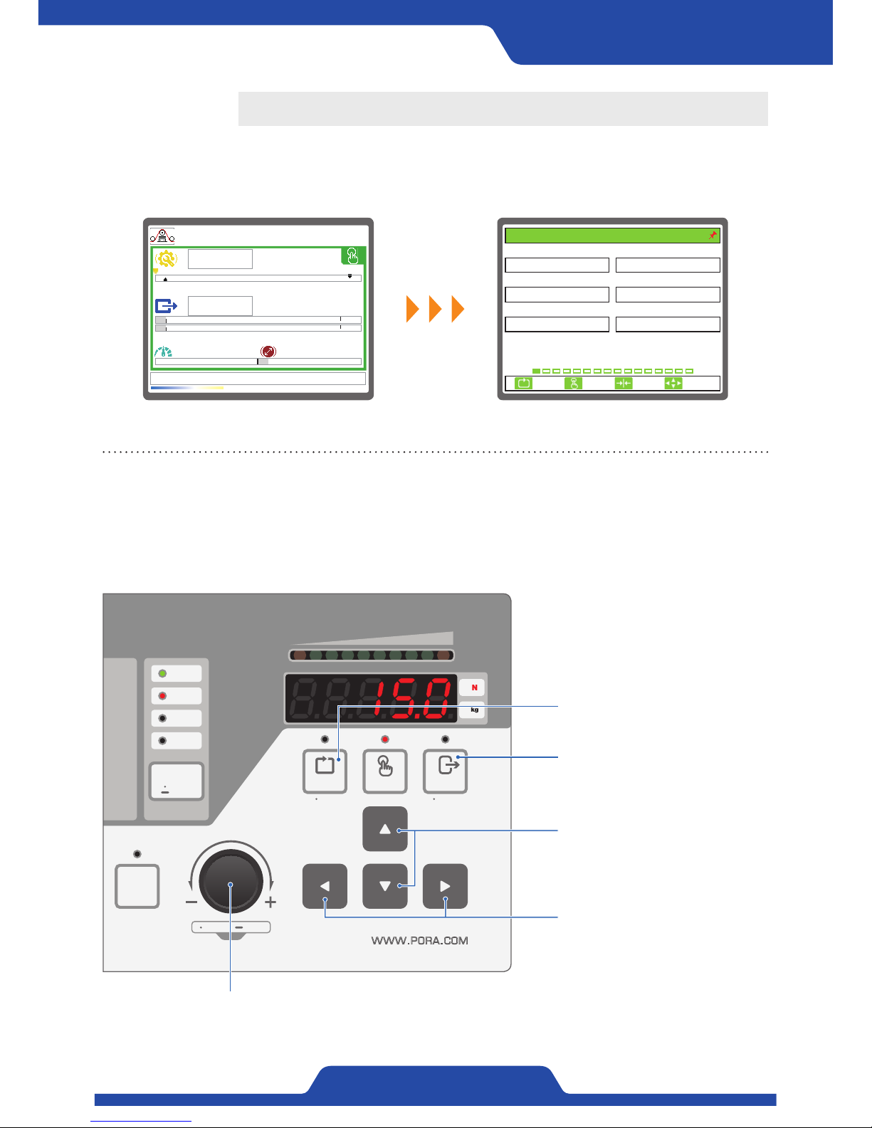
When pressing [Dial button] longer at front operational part, the screen like below will be shown.
0.0kg
0.0kg
0.0mpm 100.0mm
T
5.8%
~
Guidance on a button to be used when setting a
menu
AUTO
ZEROLOCK PRESET
MANU OUT
100%0%
DIAL
SELECT SET UP
ESC ENTER
WWW.PORA.COM
Fn
HEALTH
ALARM
ZERO
REMOTE
DISPLAY
REMOTE
●
Dial button
- Pressing longer: Setting executed (Only available in manual mode)
- Pressing shorter: Choosing setting item
- Dial rotation: Moving setting item or changing figures
Input button:
Using as a setting input button
Cancel button:
Using as a setting cancel button
Up/down button:
Moving a menu item to upward or
downward
Left/Right button:
Moving to left/right
Setting
1. TENSION UNIT 2. MAIN DISPLAY
3. 언어/LANGUAGE 4. START OPERATION
5. OP. MEMORY 6. DEFAULT RESET
kg
ENGLISH
BAR GRAPH
NOUSE
LOCAL
1. BASIC SET
ESC CLR SET
SELECT
Page 28
26
PORA ELECTRIC MACHINERY CO.,LTD.
Tension Controller
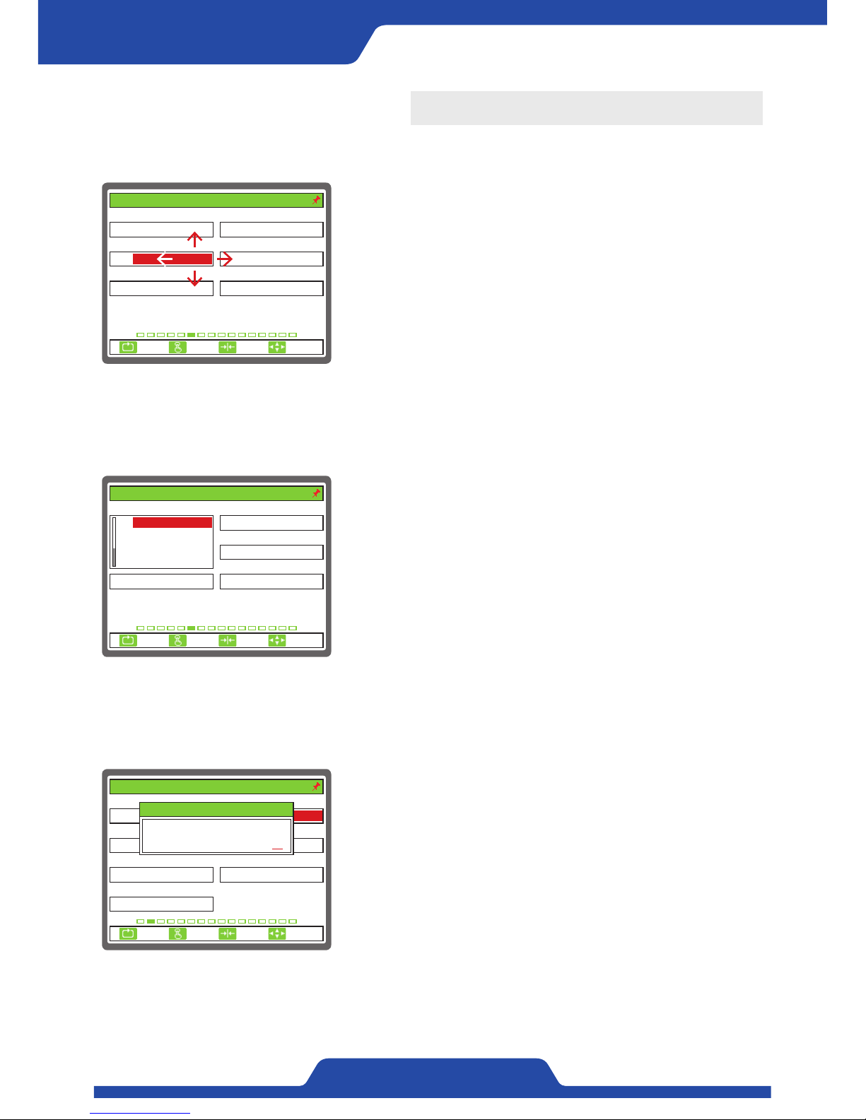
The way of setting
2) Select item
- In case of data which a user needs to select, when pressing [Enter
button] at the same time with an item being activated, items which
can choose below relevant data are shown.
- In case that there are lots of select items, scroll bar at the left of data
comes out and it is able to move an item within data select window
by using [Up/down] button.
1) Moving an item, select, input
- It is able to change a screen using [Up/down/left/right button] and
move setting item inside a screen.
- It is able to check the current location from the color of a setting
data.
- It is able to activate relevant item by pressing [Enter button] in the
item a user hopes to set.
- The way of setting changes depending on the shape of data which a
user wants to set.
3) Input number
- In case of data which needs to be input number directly, a pop-up to
input number comes out.
- It is able to move ciphers by using [Up/down/left/right button] to set
number.
- On pop-up, it shows the maximum figures selectable, the data being
set before and the data being used now.
1. ANALOG 1 2. ANALOG 1 INPUT
3. ANALOG 2 4. ANALOG 2 INPUT
5. ANALOG 3 6. ANALOG 3 INPUT
UNUSE 0...10V
0...10VUNUSE
0...10V
6. ANALOG INPUT SEL.
UNUSE
ESC CLR SET
SELECT
1. ANALOG 1 2. ANALOG 1 INPUT
3. ANALOG 2 4. ANALOG 2 INPUT
5. ANALOG 3 6. ANALOG 3 INPUT
UNUSE
0...10V
0...10VUNUSE
0...10V
6. ANALOG INPUT SEL.
ESC CLR SET
SELECT
TENSION
TORQUE
LINESPEED
UNUSE
1. SENSOR SELECT 2. SENSOR SIG(mV/V)
3. FULL SCALE(kg, N) 4. CAL.TENSION(kg, N)
5. ZERO INPUT(BCD) 6. SPAN INPUT(BCD)
100
PRTL
4095/ 40950/ 0
7. CALI. SCALE(%)
100.0
30
2. TENSION CALIBRATION
3.0
ESC CLR SET
SELECT
Max. 35.0
Curr. 3.0
2. SENSOR SIG(mV/V)
3.0
Page 29
27
PORA ELECTRIC MACHINERY CO.,LTD.
PR-DTC-4100.A / AD
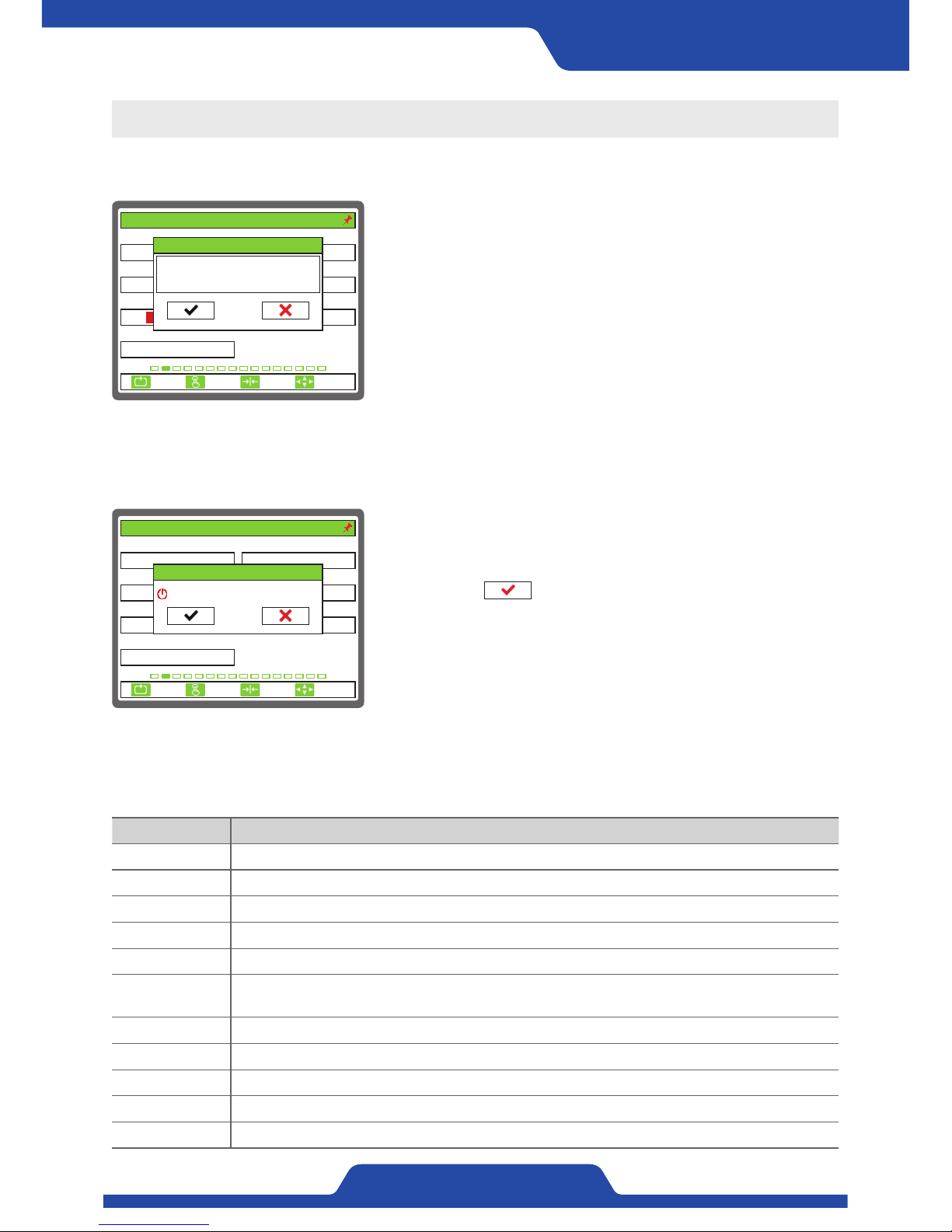
4) Input BCD
- In case that it needs to input BCD data, a pop-up comes out as well.
However, it is not possible to input number.
- It is selectable if a user inputs current data or cancel it by using [Left/
right button].
- On pop-up, data which was input before and BCD data which is
being read currently are shown.
6) Unit guidance
Unit Guidance
mV/V It means the feature of tension detector.
kg, N It means N tension.
BCD It means AD data which BCD controller processes.
% This is data which is set as percentage.
% FS This is a percentage data based on full scale of tension.
% RO
This is a percentage data which is on the basis of regular output of a controller.
(24V or analog output)
sec This means data which sets time.
mpm This means data which sets speed.
um This means data which sets width of materials.
mm This means data which sets length unit. (Diameter)
xN This means ratio of data which is set.
1. SENSOR SELECT 2. SENSOR SIG(mV/V)
3. FULL SCALE(kg, N) 4. CAL.TENSION(kg, N)
5. ZERO INPUT(BCD) 6. SPAN INPUT(BCD)
100
PRTL
7. CALI. SCALE(%)
100.0
30
3.0
2. TENSION CALIBRATION
ESC CLR SET
SELECT
0/ 0
4095/ 4095
Curr. 0/ 0
5. ZERO INPUT(BCD)
-150/ -150
5) Complete setting
1. SENSOR SELECT 2. SENSOR SIG(mV/V)
3. FULL SCALE(kg, N) 4. CAL.TENSION(kg, N)
5. ZERO INPUT(BCD) 6. SPAN INPUT(BCD)
100
0/ 0
PRTL
7. CALI. SCALE(%)
100.0
30
3.0
2. TENSION CALIBRATION
ESC CLR SET
SELECT
4095/ 4095
SETUP
DO YOU WANT TO EXIT?
- If pressing [Cancel button] in every setting mode, main setting item
will be activated and pressing [Cancel button] again, a pop-up
window for termination will appear.
- Please select check using [Left/right button], and press [Enter
button] to complete setting mode.
Page 30
28
PORA ELECTRIC MACHINERY CO.,LTD.
Tension Controller
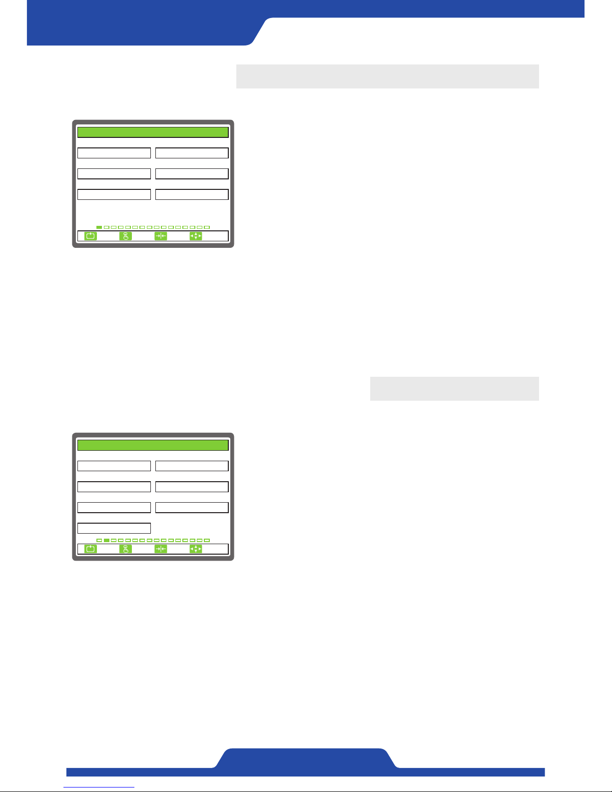
1. BASIC SET
These are the items which needs to be set basically.
1) TENSION UNIT: It is to set the unit of tension which will be shown on
a screen.
●
Setting item: kg, N
2) MAIN DISPLAY: It is to set the mode of main display.
●
Setting item: BAR GRAPH, TREND GRAPH, DATA
3) 언어/LANGUAGE: It is to set the language.
●
Setting item: 한국어(Korean), ENGLISH, 中文(Chinese)
4) START OPERATION: It is to set the way of operation when turning on
the power.
●
Setting item: LOCAL, REMOTE
1. TENSION UNIT 2. MAIN DISPLAY
3. 언어/LANGUAGE 4. START OPERATION
5. OP. MEMORY 6. DEFAULT RESET
kg
ENGLISH
BAR GRAPH
NOUSE
LOCAL
1. BASIC SET
ESC CLR SET
SELECT
5) OP. MEMORY: It is to set to decide whether a controller remembers previous operation mode when turning off
the power.
●
Setting item: USE, UNUSE
6) DEFAULT RESET: This is to initialize data (back to factory setting).
●
Setting item: NO, EXVEPT CALI, ALL RESET
- NO: This does not initialize data.
- EXVEPT CALI: Data which calibrates tension is not initialized.
- ALL RESET: All data including tension calibration data are initialized.
2. TENSION CALIBRATION
It is to set the items related tension calibration.
1) SENSOR SELECT: It is to set the sensor a user wants to use.
●
Setting item: PRTL, PRLX, PRTP, DANCER ROLL
- Setting value of [2. SENSOR SIG(mV/V)] changes automatically
depending on PRTL, PRLX, PRTP, DANCER ROLL. Dancer roll is only
selectable when dancer roll is set at analog input in main item of [6.
SPAN INPUT(BCD)]
2) SENSOR SIG(mV/V): It is to input the output specifications of a
tension detector.
- Setting range: 1.0 ~ 35.0
3) FULL SCALE(kg, N): It is to set the maximum values of used tension.
- Setting range: 0 ~ 20000
1. SENSOR SELECT 2. SENSOR SIG(mV/V)
3. FULL SCALE(kg, N) 4. CAL.TENSION(kg, N)
5. ZERO INPUT(BCD) 6. SPAN INPUT(BCD)
100
0/ 0
PRTL
7. CALI. SCALE(%)
100.0
30
3.0
2. TENSION CALIBRATION
ESC CLR SET
SELECT
4095/ 4095
4) CAL.TENSION(kg, N): It is to input the weight of a counterweight which becomes the standard of tension
calibration.
- Setting range: 0 ~ 20000
5) ZERO INPUT(BCD): It is to input the zero point of a tension detector.
- Setting range: -32767 ~ 32767
- Please input under the condition that a material and a counterweight are all removed.
6) SPAN INPUT(BCD): It is to input the data of a tension detector using a counterweight for calibration.
- Setting range: -32767 ~ 32767
7) CALI. SCALE(%): It is to calibrate tension by adjusting current scale of tension when there is not a
counterweight for calibration.
- Setting range: 0.0 ~ 1000.0
- Please only use this function when it is possible to estimate current tension.
Page 31
29
PORA ELECTRIC MACHINERY CO.,LTD.
PR-DTC-4100.A / AD
3. TENSION CONTROL
It is to set the items related to tension control.
1) TENSION ZONE: It is to set the system position which controls
tension.
●
Setting item: UNWIND, REWIND
- Taper control is only possible when setting rewind.
2) ZERO RANGE(% FS): It is to set the range indicating tension as zero
point.
- Setting range: 0.0 ~ 10.0
3) TENSION LMT(% FS): It is to set the maximum values of target
tension.
- Setting range: 0.0 ~ 100.0
- It is not able to adjust target tension more than set-up values.
4) TENSION HI(% FS): It is to set the lower limit of tension.
- Setting range: 0.0 ~ 100.0
- An alarm will occur if tension is detected more than set-up values.
5) TENSION LOW(% FS): It is to set the lower limit of tension.
- Setting range: 0.0 ~ 100.0
- An alarm will occur if tension is detected lesser than set-up values.
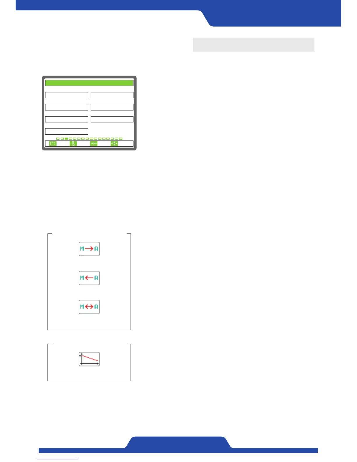
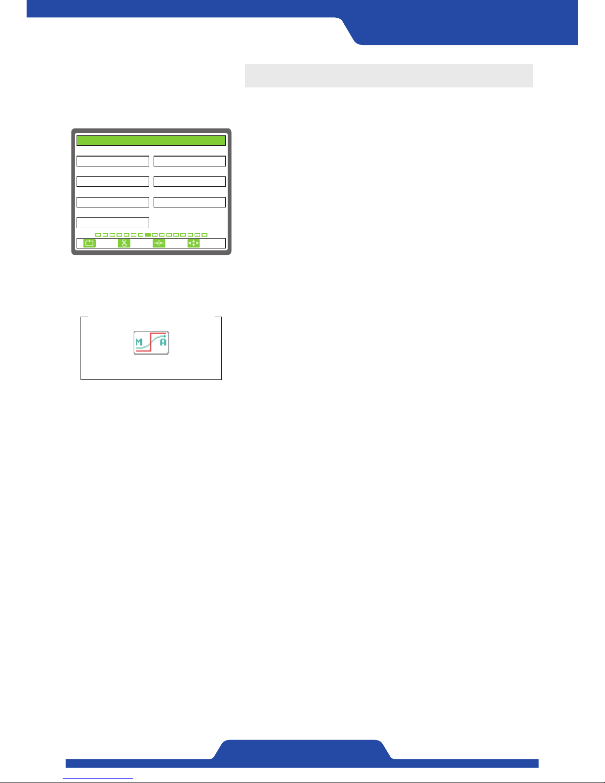
6) M/A CHANGE: When switching manual/auto mode, it is selectable
whether to interlock target tension and controlled
output values or not.
●
Setting item:
UNUSE, MANU-->AUTO, MANU<--AUTO, MANU<->AUTO
- MANU-->AUTO: When switching from manual mode to automatic
mode, current tension values is applied as target
tension.
- MANU<--AUTO: When switching from automatic mode to manual
mode, current output values is applied as manual
torque output values.
- MANU<->AUTO: The above all two things are applied.
7) TAPER USE: It is selectable whether to use taper tension function or
not.
●
Setting item: UNUSE, USE
- When setting‘use’, set-up values within main item of [9. TAPER] will
be applied.
TAPER USE - USE
An icon shown on a screen
1. TENSION ZONE 2. ZERO RANGE(% FS)
3. TENSION LMT(% FS) 4. TENSION HI(% FS)
100.0
UNWIND
7. TAPER USE
UNUSE
5. TENSION LOW(% FS)
0.0
6. M/A CHANGE
UNUSE
100.0
0.5
3. TENSION CONTROL
ESC CLR SET
SELECT
An icon shown on a screen
M/A CHANGE - MANU-->AUTO
M/A CHANGE - MANU<--AUTO
M/A CHANGE - MANU<->AUTO
Page 32
30
PORA ELECTRIC MACHINERY CO.,LTD.
Tension Controller
4. CONTROL OUTPUT
It is to set the items related to control output.
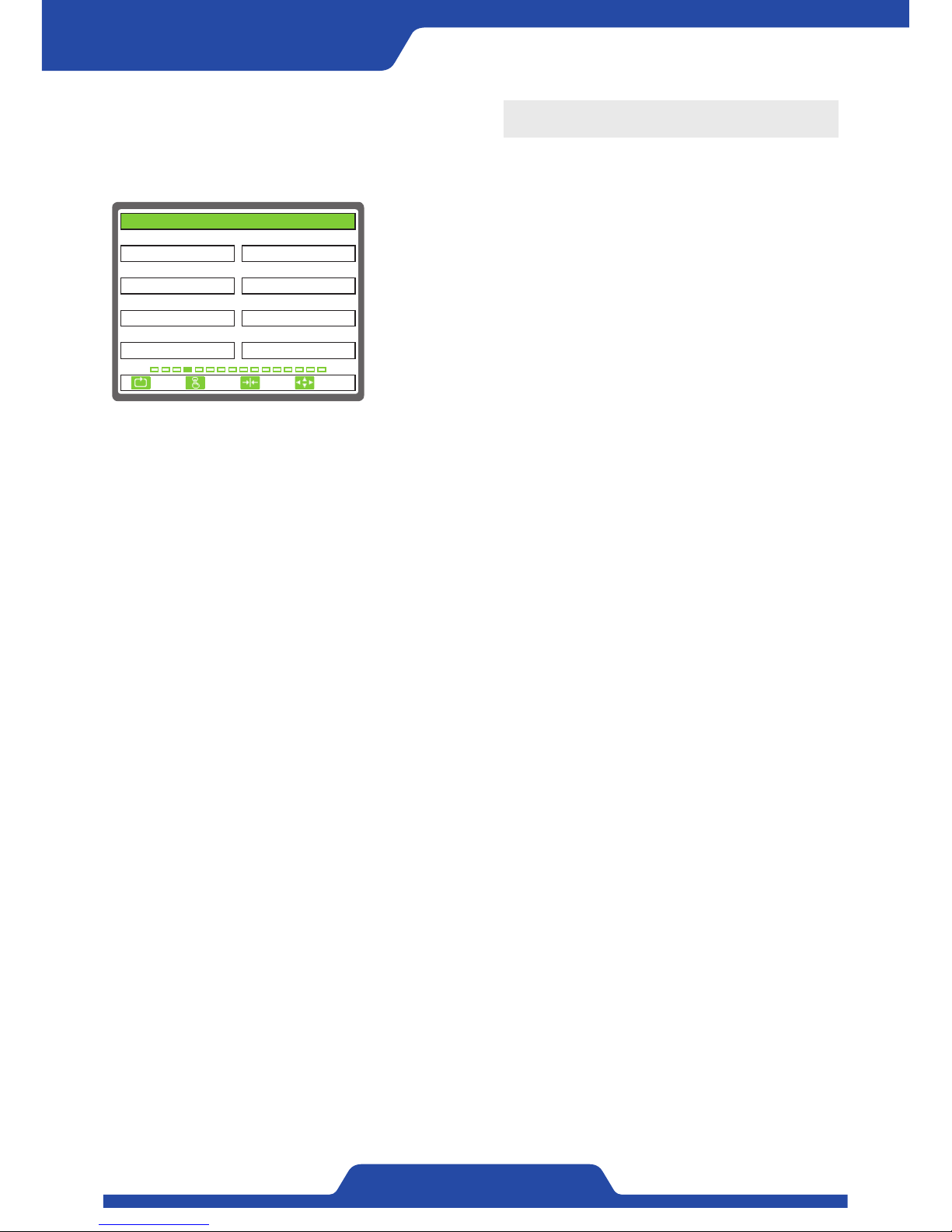
1) CONTROL REEL: It is to set a scroll which controls tension.
●
Setting item: A, B
2) CONTROL POL.: It is to set the direction of control output.
●
Setting item: NORMAL, REVERSE
- NORMAL: In case that measured tension is lower than target tension,
output value goes up.
- REVERSE: It does opposite operation against forward direction.
3) EXCITATION(% RO): This set-up is able to keep magnetism to
prevent powders inside powder brake and
clutch from being lumped.
- Setting range: 0.0 ~ 100.0
- If control tension becomes OFF, output does not go down lesser than
set-up values.
4) OUTPUT LMT(% RO): It is to set the maximum values of control
tension.
- Setting range: 0.0 ~ 100.0
- Control output dose not go up more than set-up values.
5) PRE OUT-A(% RO): It is to set the standby voltage of A shaft when
switching a shaft.
- Setting range: 0.0 ~ 100.0
6) PRE OUT-B(% RO): It is to set the standby voltage of B shaft when
switching a shaft.
- Setting range: 0.0 ~ 100.0
7) REEL CHANGE(sec): It is to set the standby time when switching a
shaft.
- Setting range: 0.0 ~ 100.0
- The standby output will be generated to a switched shaft during set-
up standby time.
8) CHANGE COMP.(sec): It is to set the time which is kept after
completing shaft switch.
- Setting range: 0.0 ~ 999.9
- After completing switching a shaft, the standby output will be
generated to a shaft which was used before during set-up complete
times.
※NOTE
It is only able to use this shaft switch function in PR-DTC-4100.AD.
(Please refer to page 22)
1. CONTROL REEL 2. CONTROL POL.
3. EXCITATION(% RO) 4. OUTPUT LMT(% RO)
5. PRE OUT-A(% RO) 6. PRE OUT-B(% RO)
5.0
A
50.050.0
7. REEL CHANGE(sec)
5.0
8. CHANGE COMP.(sec)
5.0
100.0
NORMAL
4. CONTROL OUTPUT
ESC CLR SET
SELECT
Page 33
31
PORA ELECTRIC MACHINERY CO.,LTD.
PR-DTC-4100.A / AD
5. PID SET
It is able to set the items related to control sensitivity.
1) P GAIN: It is to set proportional control sensitivity.
●
Setting range: 0.0 ~ 10.0
2) I GAIN: It is to set integral control sensitivity.
●
Setting range: 0.0 ~ 10.0
3) D GAIN: It is to set differential control sensitivity.
●
Setting range: 0.0 ~ 10.0
※NOTE
For setting P·I·D sensitivity, please enter P·I·D sensitivity setting
mode while in automatic mode and check control output to adjust each
figure. (Please refer to page 23)
1. P GAIN 2. I GAIN
3. D GAIN
0.3
0.1
0.5
5. PID SET
ESC CLR SET
SELECT
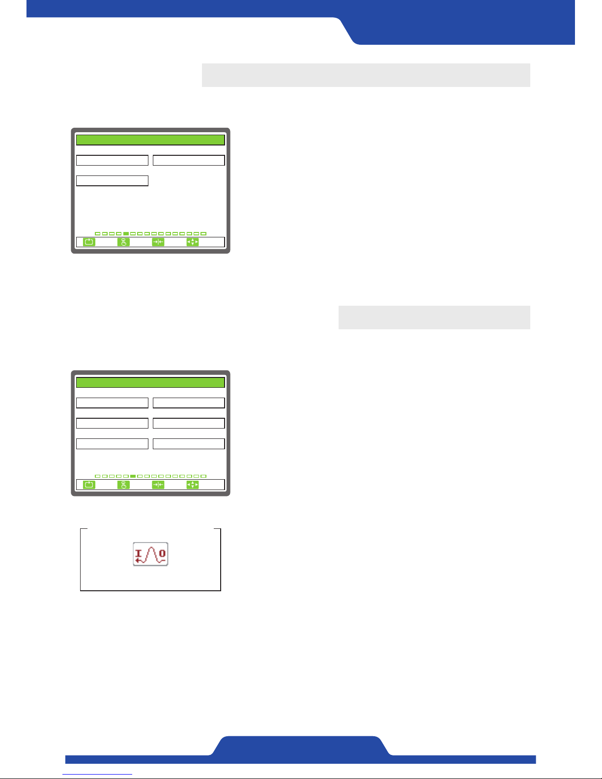
6. ANALOG INPUT SEL.
It Is able to set the items related to analog input.
1) ANALOG 1: It Is able to set the items related to analog input.
●
Setting item: UNUSE, TENSION, TORQUE, LINESPEED, DIAMETER,
DANCER ROLL
2) ANALOG 1 INPUT: It is to set the input signal of Analog No. 1
terminal.
●
Setting item: 0...10V, 4...20mA
- The data will not be read correctly if the setting is wrong.
3) ANALOG 2: It is to set the items which is input to Analog No. 2
terminal.
- Setting item: UNUSE, TENSION, TORQUE, LINESPEED, DIAMETER,
DANCER ROLL
4) ANALOG 2 INPUT: It is to set the input signal of Analog No. 2
terminal.
●
Setting item: 0...10V, 4...20mA
- The data will not be read correctly if the setting is wrong.
5) ANALOG 3: It is to set the items which is input to Analog No. 3
terminal.
●
Setting item: UNUSE, TENSION, TORQUE, LINESPEED, DIAMETER,
DANCER ROLL
6) ANALOG 3 INPUT: It is to set the input signal of Analog No. 3
terminal.
●
Setting item: 0...10V, 4...20mA
- The data will not be read correctly if the setting is wrong.
※NOTE
An icon will not be shown when not using Analog 1, 2, 3.
ANALOG - Setting
An icon shown on a screen
1. ANALOG 1 2. ANALOG 1 INPUT
3. ANALOG 2 4. ANALOG 2 INPUT
5. ANALOG 3 6. ANALOG 3 INPUT
UNUSE
UNUSE
0...10V
0...10VUNUSE
0...10V
6. ANALOG INPUT SEL.
ESC CLR SET
SELECT
Page 34
32
PORA ELECTRIC MACHINERY CO.,LTD.
Tension Controller
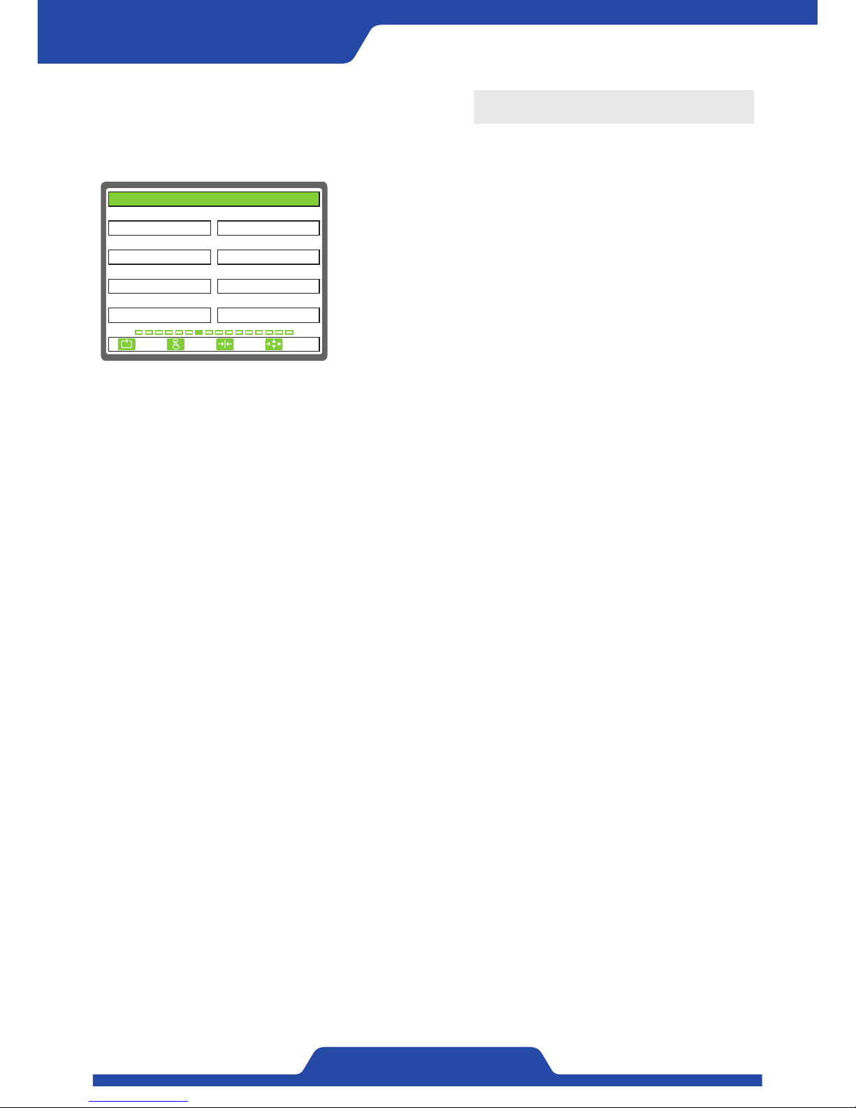
7. ANALOG INPUT SET
It is able to set analog input items.
1) REF. ZERO(BCD): It is to set the minimum values of analog input
signal for target tension.
- Input range: 0 ~ 16383
2) REF. SPAN(BCD): It is to set the maximum values of analog input
signal for target tension.
- Input range: 0 ~ 16383
3) OFFSET(% FS): It is to set the offset values which will add to target
tension. (Analog input signal).
- Setting range: 0.0 ~ 100.0
4) SPAN(xN): Please do multiply values which is set to target tension.
(Analog tension value)
- Setting range: 0.0 ~ 10.0
5) TRQ. ZERO(BCD): Please input the minimum values of analog input
signal for manual output.
- Input range: 0 ~ 16383
6) TRQ. SPAN(BCD): Please input the maximum values of analog input
signal for manual output.
- Input range: 0 ~ 16383
7) OFFSET(% FS): It is to set the offset values which will add to manual
output. (Analog input signal)
- Setting range: 0.0 ~ 100.0
8) SPAN(xN): Please do multiply the values which is set to manual
output. (Analog input signal)
- Setting range: 0.0 ~ 10.0
1. REF. ZERO(BCD) 2. REF. SPAN(BCD)
3. OFFSET(% FS) 4. SPAN(xN)
5. TRQ. ZERO(BCD) 6. TRQ. SPAN(BCD)
0.0
0
163830
7. OFFSET(% RO)
0.0
8. SPAN(xN)
1.0
1.0
16383
7. ANALOG INPUT SET
ESC CLR SET
SELECT
Page 35
3 3
PORA ELECTRIC MACHINERY CO.,LTD.
PR-DTC-4100.A / AD
8. LINE SPEED
It is able to set the items related line speed.
1) LINESPEED: It is to select the signal which can check line speed.
●
Select item: TG, ANALOG
- TG: It uses TG input terminal.
- ANALOG: It uses 1 channel of 3 channels of analog input.
2) SPEED MIN(mpm): It is to set the lowest values of line speed input
signal.
- Setting range: 0.0 ~ 1000.0
3) SPEED MIN(BCD): It is to input analog values at lowest speed which
is set-up the above No.2 item.
- Input range: 0 ~ 16383
4) SPEED MAX(mpm): It is to set the maximum values of line speed
input signal.
- Setting range: 0.0 ~ 1000.0
5) SPEED MAX(BCD): It is to input analog values at maximum speed
which is set-up the above No.4 item.
- Input range: 0 ~ 16383
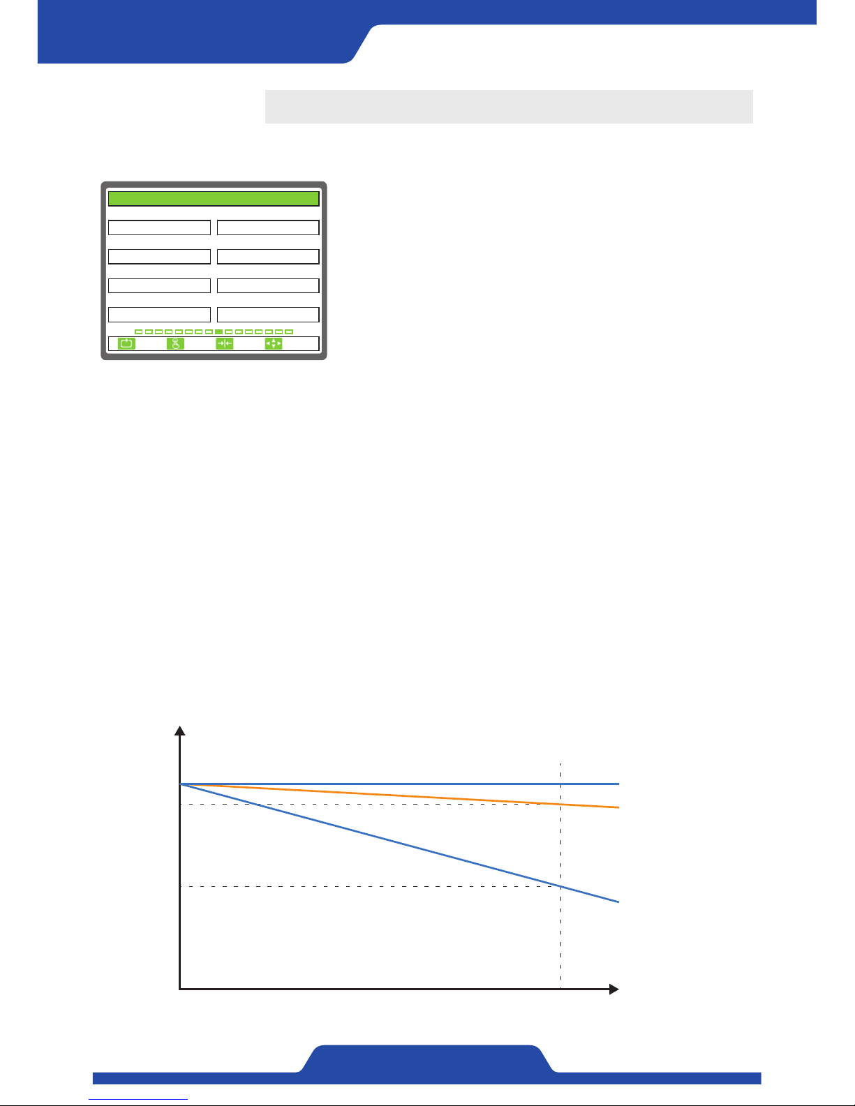
6) M/A MODE CHANGE: It is to set whether to switch manual/automatic
mode or not by using line speed.
- Select item: UNUSE, USE
7) CHANGE REF.(mpm): It is to set the line speed which switches the
mode.
- Setting range: 0.0 ~ 1000.0
- If line speed is higher than set-up values, manual mode will be
switched to automatic mode and if it is lower than set-up values,
automatic mode will be switched to manual mode.
M/A MODE CHANGE - USE
An icon shown on a screen
1. LINESPEED 2. .SPEED MIN(mpm)
3. SPEED MIN(BCD) 4. SPEED MAX(mpm)
5. SPEED MAX(BCD) 6. M/A MODE CHANGE
0
TG
UNUSE16383
7. CHANGE REF.(mpm)
15.0
200.0
0.0
8. LINESPEED
ESC CLR SET
SELECT
Page 36
34
PORA ELECTRIC MACHINERY CO.,LTD.
Tension Controller
9. TAPER
It is able to set the items related taper control.
1) DIAMETER INPUT: It is to set the way of detecting diameter
operation.
●
Select item: PULSE, ANALOG
- PULSE: Calculate diameter operation using pulse signal installed to a
scroll.
- ANALOG: Calculate diameter operation using 1 channel in 3 channels of
Analog input.
2) THICKNESS(um): It is to set the width of materials.
- Setting range: 0.0 ~ 2000.0
- It is applied when [1. DIAMETER INPUT] is selected to‘Pulse’.
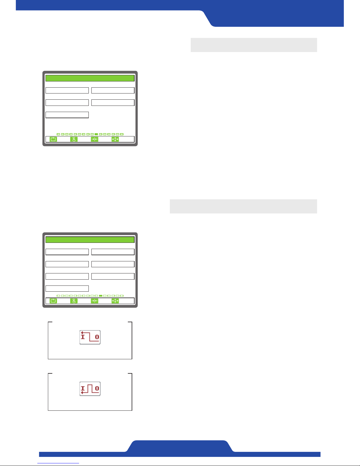
※NOTE
As the diameter of roll increases, decrease tension value softly. It will decrease the stress
inside roll and lead to reduce defect of wrapped roll.
1. DIAMETER INPUT 2. THICKNESS(um)
3. REEL PULSE 4. TAPER RATIO(%)
5. DIAMETER MIN(mm) 6. DIAMETER MIN(BCD)
1
ANALOG
0100.0
7. DIAMETER MAX(mm)
1000.0
8. DIAMETER MAX(BCD)
16383
100.0
100.0
9. TAPER
ESC CLR SET
SELECT
3) REEL PULSE: It is to set the input number of pulse per one rotation.
- Select item: 1, 2, 4, 8
- It is applied when [1. DIAMETER INPUT] is selected to‘Pulse’.
4) TAPER RATIO(%): It is to set the ratio of taper.
- Setting range: 0.0 ~ 100.0
5) DIAMETER MIN(mm): It is to set the minimum diameter of materials.
- Setting range: 0.0 ~ 2000.0
6) DIAMETER MIN(BCD): It is to input analog values when materials are minimum diameter.
- Input range: 0 ~ 16383
7) DIAMETER MAX(mm): It is to set the maximum diameter of materials.
- Setting range: 0.0 ~ 2000.0
- It is applied when [1. DIAMETER INPUT] is selected to‘Analog’.
8) DIAMETER MAX(BCD): It is to input analog values when materials are maximum diameter.
- Input range: 0 ~ 16383
- It is applied when [1. DIAMETER INPUT] is selected to‘Analog’.
Tension (kg)
10
9
5
0
MAX
Diameter (mm)
Taper ratio 100%
Taper ratio 90%
Taper ratio 50%
Page 37
35
PORA ELECTRIC MACHINERY CO.,LTD.
PR-DTC-4100.A / AD
10. ANALOG OUTPUT
It is able to set the items related to analog output.
1) CONTROL OUTPUT: It is to select analog output which is used as
control output.
●
Select item: 0...5V, 0...10V, -10...+10V, 4...20mA, 0...20mA
- Please sort voltage, current and use relevant terminal.
2) CONTROL POLARITY: It is to set the way of analog control output.
●
Select item: NORMAL, REVERSE
3) CONTROL LMT(% RO): It is to set the maximum values of analog
control output.
- Setting range: 0.0 ~ 100.0
1. CONTROL OUTPUT 2. CONTROL POLARITY
3. CONTROL LMT(% RO) 4. TENSION OUTPUT
5. TENSION POLARITY
100.0
0...10V
NORMAL
0...5V
NORMAL
10. ANALOG OUTPUT
ESC CLR SET
SELECT
11. DIGITAL INPUT
It is able to set the items which will be used digital input terminal.
1) DIGITAL 1: It is to select the items which will be used digital input
No. 1 terminal.
●
Select item: UNUSE, AUTO, MANU, OUT ON/OFF, ZERO, EMS,
CHANGE, DIA.RESET
2) DIGITAL 2: It is to select the items which will be used digital input
No. 2 terminal.
●
Select item: UNUSE, AUTO, MANU, OUT ON/OFF, ZERO, EMS,
CHANGE, DIA.RESET
3) DIGITAL 3: It is to select the items which will be used digital input
No. 3 terminal.
●
Select item: UNUSE, AUTO, MANU, OUT ON/OFF, ZERO, EMS,
CHANGE, DIA.RESET
4) DIGITAL 4: It is to select the items which will be used digital input
No. 4 terminal.
●
Select item: UNUSE, AUTO, MANU, OUT ON/OFF, ZERO, EMS,
CHANGE, DIA.RESET
5) DIGITAL 5: It is to select the items which will be used digital input
No. 5 terminal.
●
Select item: UNUSE, AUTO, MANU, OUT ON/OFF, ZERO, EMS,
CHANGE, DIA.RESET
6) DIGITAL 6: It is to select the items which will be used digital input
No. 6 terminal.
●
Select item: UNUSE, AUTO, MANU, OUT ON/OFF, ZERO, EMS,
CHANGE, DIA.RESET
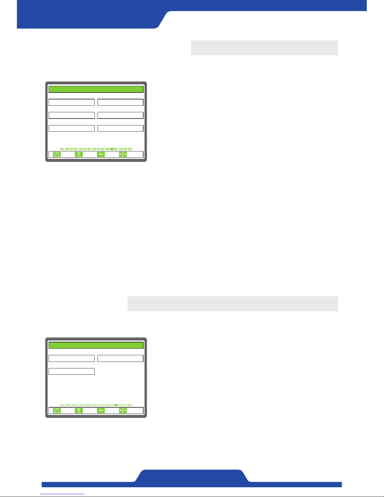
7) INPUT TYPE: It is to select the way of digital input signal.
●
Select item: HOLD, PULSE
- When selecting‘hold’, relevant operation is executed only while
relevant input is being kept.
INPUT TYPE - HOLD
An icon shown on a screen
INPUT TYPE - PULSE
An icon shown on a screen
1. DIGITAL 1 2. DIGITAL 2
3. DIGITAL 3 4. DIGITAL 4
5. DIGITAL 5 6. DIGITAL 6
ZERO
AUTO
DIA. RESETCHANGE
7. INPUT TYPE
HOLD
EMS
OUT ON/OFF
11. DIGITAL INPUT
ESC CLR SET
SELECT
4) TENSION OUTPUT: It is to select analog output which is going to be used as tension output.
●
Select item: 0...5V, 0...10V, 4...20mA, 0...20mA
- Please sort voltage, current and use relevant terminal.
5) TENSION POLARITY: It is to set the way of analog tension output.
●
Select item: NORMAL, REVERSE
- If the tension is 0 in reverse way, maximum analog values is outputted.
Page 38
36
PORA ELECTRIC MACHINERY CO.,LTD.
Tension Controller
12. DIGITAL OUTPUT
It is to set the items which will be used to digital output terminal.
13. FILTER
It is able to set delay time to tension indication and analog input/output signal.
1) TENSION(sec): It is to set delay time for tension indication.
- Setting range: 0.1 ~ 10.0
2) ANALOG IN(sec): It is to set delay time for analog input.
- Setting range: 0.1 ~ 10.0
3) ANALOG OUT(sec): It is to set delay time for analog output.
- Setting range: 0.1 ~ 10.0
※NOTE
When the motion of relevant data is severe, please adjust appropriate
value by going up slowly filtering time.
1. DIGITAL 1 2. DIGITAL 2
3. DIGITAL 3 4. DIGITAL 4
5. DIGITAL 5 6. DIGITAL 6
OUT ON/OFF
AUTO
TENSION ERRSENSOR ERR
ZERO
MANU
12. DIGITAL OUTPUT
ESC CLR SET
SELECT
1) DIGITAL 1: It is to select the items which will be used to No. 1 digital
input terminal.
●
Select item: AUTO, MANU, OUT ON/OFF, ZERO, EMS, A/B, TENSION
HI, TENSION LOW, SENSOR ERR, TENSION ERR,
DIAMETER MAX
2) DIGITAL 2: It is to select the items which will be used to No. 2 digital
input terminal.
●
Select item: AUTO, MANU, OUT ON/OFF, ZERO, EMS, A/B, TENSION
HI, TENSION LOW, SENSOR ERR, TENSION ERR,
DIAMETER MAX
3) DIGITAL 3: It is to select the items which will be used to No. 3 digital input terminal.
●
Select item: AUTO, MANU, OUT ON/OFF, ZERO, EMS, A/B, TENSION HI, TENSION LOW, SENSOR ERR,
TENSION ERR, DIAMETER MAX
4) DIGITAL 4: It is to select the items which will be used to No. 4 digital input terminal.
●
Select item: AUTO, MANU, OUT ON/OFF, ZERO, EMS, A/B, TENSION HI, TENSION LOW, SENSOR ERR,
TENSION ERR, DIAMETER MAX
5) DIGITAL 5: It is to select the items which will be used to No. 5 digital input terminal.
●
Select item: AUTO, MANU, OUT ON/OFF, ZERO, EMS, A/B, TENSION HI, TENSION LOW, SENSOR ERR,
TENSION ERR, DIAMETER MAX
6) DIGITAL 6: It is to select the items which will be used to No. 6 digital input terminal.
●
Select item: AUTO, MANU, OUT ON/OFF, ZERO, EMS, A/B, TENSION HI, TENSION LOW, SENSOR ERR,
TENSION ERR, DIAMETER MAX
1. TENSION(sec) 2. ANALOG IN(sec)
3. ANALOG OUT(sec)
0.3
0.3 0.3
13. FILTER
ESC CLR SET
SELECT
Page 39
37
PORA ELECTRIC MACHINERY CO.,LTD.
PR-DTC-4100.A / AD
14. USER SET
It is able to set the items related to the rest function.
1) OUTPUT HOLD: It is to keep the current control output consistently.
Select whether to use this function by detecting
tension change or line speed.
●
Select item: UNUSE, TENSION, LINESPEED
2)
REF. TENSION(% FS): In case of selecting No.1 item to be tension
and when measured tension is lower than setup tension, current control output is being kept
for certain times.
- Setting range: 0.0 ~ 100.0
3) REF. SPEED(mpm): In case of selecting No.1 to be line speed and
when measured line speed is lower than set-up
speed, current control output is being kept for
certain times.
- Setting range: 0.0 ~ 1000.0
4) HOLD TIME(sec): It is to set the times when output maintaining
operation is run.
- Setting range: 0.0 ~ 100.0
5) HOLD RATIO(%): It is to set control output ratio while output
maintaining operation is run.
- Setting range: 0.0 ~ 1000.0
6)
EMS TIME(sec): It is to set the times when emergency stop operation
is run. Emergency stop function can be operated by
using external digital input or communication.
- Setting range: 0.0 ~ 100.0
7) EMS RATIO(%): It is to set control output ratio when emergency stop
function is run.
- Setting range: 0.0 ~ 1000.0
8) BUZZER: It is to set whether to use buzzer or not.
●
Select item: UNUSE, USE
OUTPUT HOLD - Setting
An icon shown on a screen
1. OUTPUT HOLD 2. REF. TENSION(% FS)
3. REF. SPEED(mpm) 4. HOLD TIME(sec)
5. HOLD RATIO(%) 6. EMS TIME(sec)
10.0
UNUSE
3.0100.0
7. EMS RATIO(%)
100.0
8. BUZZER
USE
3.0
10.0
14. USER SET
ESC CLR SET
SELECT
Page 40
38
PORA ELECTRIC MACHINERY CO.,LTD.
Tension Controller
15. DISPLAY
It is able to set the items related to screen display.
1) TENSION DISPLAY: It is to select the way of tension display.
●
Select item: TOTAL, LEFT, RIGHT
- When selecting Left/Right, it is controlled automatically by only using
the tension of relevant tension detector.
2) DECIMAL POINT: It is to set a cipher below decimal point of tension
which is shown on FND.
- Setting range: 1, 0.1, 0.01
3) L OFFSET(% FS): It is to set offset values which will be added to
tension display at a left detector.
- Setting range: 0.0 ~ 100.0
4) L SPAN(xN): It is to set tension display ratio of a left detector.
- Setting range: 0.0 ~ 10.0
5) R OFFSET(% FS): It is to set offset values which will be added to
tension display at a right detector.
- Setting range: 0.0 ~ 100.0
6) R SPAN(xN): It is to set tension display ratio at a right detector.
- Setting range: 0.0 ~ 10.0
7) BRIGHTNESS(%): It is to set brightness of LCD window.
- Setting range: 10.0 ~ 100.0
8) OUTPUT DISPLAY: It is to set the unit of indicating control output.
●
Select item: %, V
- %: Control output is indicated to 0~100%.
- V: Control output is indicated to 0~23.5V.
1. TENSION DISPLAY 2. DECIMAL POINT
3. L OFFSET(% FS) 4. L SPAN(xN)
5. R OFFSET(% FS)
0.0
TOTAL
6. R SPAN(xN)
1.0
8. OUTPUT DISPLAY
%
0.0
7. BRIGHTNESS(%)
80.0
1.0
0.1
15. DISPLAY
ESC CLR SET
SELECT
16. INTERFACE CHECK
It is possible to check the internal data of a controller.
1. INTERNAL DATA:
KEY: It shows the data on front buttons.
DIP: It shows setting condition of dip switch in operational part from
board side.
D-IN: It shows the condition of digital input data.
ENC: It shows counter values of switch.
VCC: It shows power condition of +12V inside a controller.
VEE: It shows power condition of -12V inside a controller.
VDD: It shows power condition of +5V inside a controller.
TEMP: It shows temperature of driver board.
SEN1: It shows signal data of a left detector.
SEN2: It shows signal data of a right detector.
SEN3: It shows signal data of a left differential pickup.
SEN4: It shows signal data of a right differential pickup.
A-IN1: It shows data of No. 1 analog input signal.
A-IN2: It shows data of No. 2 analog input signal.
A-IN3: It shows data of No. 3 analog input signal.
A-IN4: It shows data of TG input signal.
1. INTERNAL DATA X. X. X
KEY :
DIP :
D-IN :
ENC :
PRX :
VCC :
VEE :
VDD :
TEMP :
0x0000
0x0000
0x0000
-5
0
12.0V
-12.0V
4.9V
34.6℃
SEN1 :
SEN2 :
SEN3 :
SEN4 :
A-IN1 :
A-IN2 :
A-IN3 :
A-IN4 :
-147
-167
0
0
0
0
0
0
16. INTERFACE CHECK
ESC CLR SET
SELECT
Page 41
39
PORA ELECTRIC MACHINERY CO.,LTD.
PR-DTC-4100.A / AD
We support 4 kinds of communication functions for this model. Please take the appropriate the way of
communication.
Using communication
1. Can 2.0A
CAN communication is used to transmit the current tension and output of PR-DTC-4100.A(D) to outside with unidirectional way. It is not to control PR-DTC-4100.A(D) from outside. It is able to use for multiplex control of powder
brake, powder clutch through connecting power amp additionally. (It transmits with the cycle of 50ms.)
The mode of CAN transmit, receive: CAN 2.0A
CAN BPS: 250kbps
CAN ID: 0x410
The length of data: 8
※The specification of CAN data can be changed without any notice.
Contents Data type Range of values Data
Remote control is activated Bit 0 0 / 1 D1
Ready for operation Bit 1 0 / 1 D1
Automatic mode is ON Bit 2 0 / 1 D1
Manual mode is ON Bit 3 0 / 1 D1
Output On/Off State Bit 4 0 / 1 D1
Tension Zero Bit 5 0 / 1 D1
Emergency Stop mode is ON Bit 6 0 / 1 D1
Control Reel A/B Bit 7 0 / 1 D1
Tension High Bit 8 0 / 1 D0
Tension Low Bit 9 0 / 1 D0
Sensor Error Bit 10 0 / 1 D0
Tension Error Bit 11 0 / 1 D0
Maximum Diameter Bit 12 0 / 1 D0
Over Load Bit 13 0 / 1 D0
Over Heat Bit 14 0 / 1 D0
Flashing cycle 1Hz Bit 15 0 / 1 D0
Contents Data type Range of values Data
Tension Total integer
-20000...20000 digit
D2~D3
[1kg, 1N]
Control Output integer
0...1000 digit
D4~D5
[0.1%]
D0 D1 D2 D3 D4 D5 D6 D7
OUT_H OUT_L TENSION_H TENSION_L CONTROL_H CONTROL_L 0x00 0x00
Data specification is as the below.
Page 42
40
PORA ELECTRIC MACHINERY CO.,LTD.
Tension Controller
2. Modbus-RTU (RS-232)
This program is to support Modbus-RTU protocol by using RS-232 communication and It is able to data setting
and external control of PR-DTC-4100.A(D). It uses RS-232 communication terminal at terminal block. Please be
sure not to confuse serial port at board side.
1) Modbus-RTU Frame
Start (logical) Address Field Function Field Data Field CRC Check
28 bits (3.5 Character times) 1 byte 1 byte n x 1byte 2 bytes
2) Function Code
Function code is a collective code of command which is offered by Modbus protocol. It is able to read or write
the values of Slave Memory (Coil, Register).
Code 1/16-bit Description I/O range
03 (0x03) 16-bit Read holding registers 40001 - 50000
06 (0x06) 16-bit Write single register 40001 - 50000
16 (0x10) 16-bit Write multiple registers 40001 - 50000
3) Exception Code
In case it happens errors such as undefined Function Code, Address, and data setting of range not permitted,
please set the values which add 0x80 from Function Code to be an error code to respond.
Code Name of error Description
01 (0x01) Illegal function It appears when requesting unpermitted operation.
02 (0x02) Illegal data address It appears when requested data address is not valid.
03 (0x03) Illegal data value It appears when requested data is beyond the bounds.
Page 43
41
PORA ELECTRIC MACHINERY CO.,LTD.
PR-DTC-4100.A / AD
4) The example of data transmission (Modbus ID of PR-DTC-4100.A(D) is 0x01.)
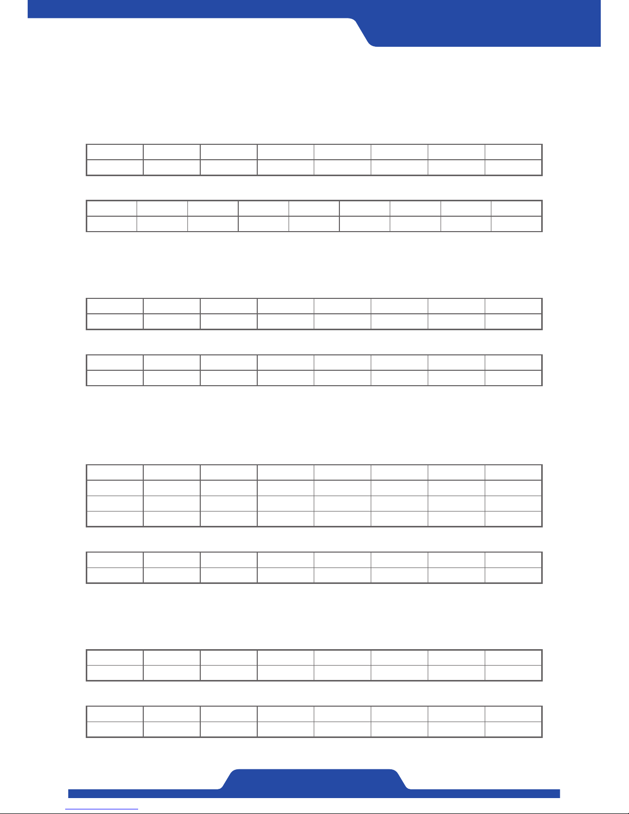
Slave ID FC ADD_H ADD_L REG_H REG_L CRC_L CRC_H
0x01 0x03 0x9C 0x4C 0x00 0x02 0x2B 0x8C
Slave ID FC ADD_H ADD_L REG_H REG_L CRC_L CRC_H
0x01 0x06 0x9C 0x4D 0x05 0xDC 0x35 0x44
Slave ID FC ADD_H ADD_L REG_H REG_L CNT -
0x01 0x10 0x9C 0x4D 0x00 0x02 0x04 -
DAT_H DAT_L DAT_H DAT_L CRC_L CRC_H - -
0x03 0xE8 0x00 0x64 0x4E 0x9B - -
Slave ID FC ADD_H ADD_L REG_H REG_L CRC_L CRC_H
0x01 0x06 0x9C 0x4D 0x05 0xDC 0x35 0x44
Slave ID FC ADD_H ADD_L REG_H REG_L CRC_L CRC_H
0x01 0x10 0x9C 0x4D 0x00 0x02 0xFF 0x8F
Slave ID FC CNT REG_H REG_L REG_H REG_L CRC_L CRC_H
0x01 0x03 0x04 0x00 0x1E 0x03 0xE8 0x9A 0x8B
4-1) 0x03: Read Holding Register
When reading 2 data values from the number of Address 40012 (0x9C4C).
Address 40012: 30 (0x001E), Address 40013: 1000 (0x03E8)
4-2) 0x06: Write Single Register
When setting the number of Address 40013 (0x9C4D) to be 1500 (0x05DC).
4-3) 0x10: Write Multiple Register
When setting connected 2ea of Address from the number of Address 40013 (0x9C4D) to be 1000 (0x03E8),
100 (0x0064).
>> Request
>> Request
>> Request
>> Response
>> Response
>> Response
Slave ID FC ADD_H ADD_L REG_H REG_L CRC_L CRC_H
0x01 0x03 0xA8 0x05 0x005 0x01 0xB4 0x6B
Slave ID FC ERR CRC_L CRC_H - - -
0x01 0x83 0x02 0xC0 0xF1 - - -
4-4) Occuring error (When requesting data of nonexistent address)
When requesting data values of nonexistent address whose the number is Address 43013 (0xA805).
>> Request
>> Response
Page 44
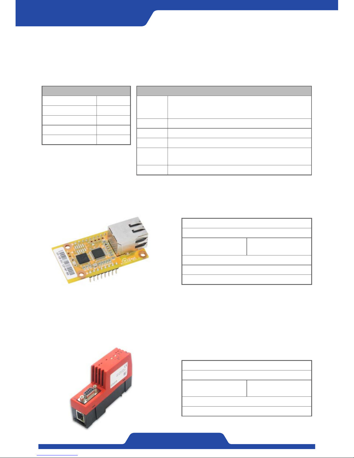
42
PORA ELECTRIC MACHINERY CO.,LTD.
Tension Controller
3. Hyper Terminal (RS-232)
It is able to check the status of operation and setting data of a product through PC. Hyperterminal is kind of a
communication program which is used to connect to communication service of normal text environment. For
further inquiry, please contact the web site or headquarter of PORA Electric Machinery Co., Ltd.
(+82-31-455-8183)
4. Ethernet (※Option)
It is able to compose communication by connecting the module as follows to the system which is comprised of
fieldbus using ethernet communication. Please ask in advance to PORA if using ethernet.
Connection: RJ45 socket
Cable: Ethernet cable, twisted pair
Baudrate:
10 Mbps or 100 Mbps
Automatic adjustment
Transmission: Half duplex or full duplex
Module Company: Wiznet
Model: WIZ550S2E
5. Profibus-DP (※Option)
It is able to compose communication by connecting the module as follows to the system which is comprised of
fieldbus using Profibus-DP. Communication through Modbus-RTU is done between PR-DTC-4100.A(D) and the
following module and then can control PR-DTC-4100.A(D) outside through Profibus-DP. Please ask in advance
to PORA regarding Profibus-DP.
Connection: RS-485 socket
Cable: Profibus cable, Shield pair
Baudrate:
9.6 kbps ~ 12 Mbps
Automatic adjustment
Module Company: Hilscher
Model: NT 50-DP-RS
Table to set port
Bit / Second (B) 115200
Data bit (D) 8
Parity (P) None
Stop bit (S) 1
Control flow (F) None
Command statement
READY?
Checking the connection of hyper terminal
( After checking connection is completed, it is able to run
below command.)
PORA? It shows the sentences of company introduction.
IDN? It shows the specifications of a product much in detail.
VERS? It shows the history of product version.
DATA ?
It is able to check the data by entering into product setting
display.
LOG? Tension and control output is shown by one second.
Page 45
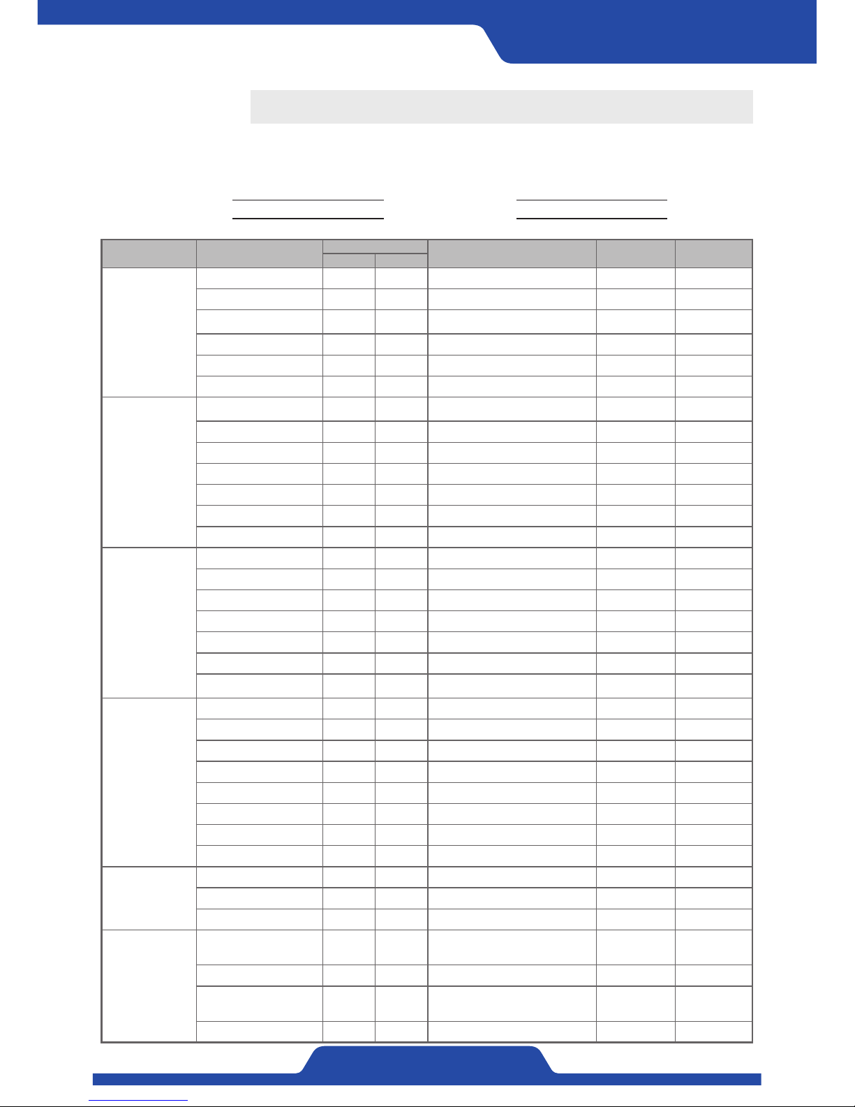
43
PORA ELECTRIC MACHINERY CO.,LTD.
PR-DTC-4100.A / AD
Setting menu item Submenu item
Modbus address
Setting range (Setting item) Initial setting Setting values
Int Hex
1. BASIC SET
1. TENSION UNIT 40001 9C41 kg, N kg
2. MAIN DISPLAY 40002 9C42 BAR GRAPH, TREND GRAPH, DATA BAR GRAPH
3. 언어/LANGUAGE 40003 9C43
한국어 (KOREAN),
ENGLISH, 中文 (CHINESE)
한국어 (KOREAN)
4. START OPERATION 40004 9C44 LOCAL, REMOTE LOCAL
5. OP. MEMORY 40005 9C45 USE, UNUSE USE
6. DEFAULT RESET 40006 9C46 NO, EXVEPT CALI, ALL RESET NO
2. TENSION
CALIBRATION
1. SENSOR SELECT 40011 9C4B
PRTL, PRLX, PRTP,
DANCER ROLL
PRTL
2. SENSOR SIG(mV/V) 40012 9C4C 1.0~35.0 3.0
3. FULL SCALE(kg,N) 40013 9C4D 0~20000 100
4. CAL.TENSION(kg,N) 40014 9C4E 0~20000 30
5. ZERO INPUT(BCD) 40015 9C4F -32767~32767 / -32767~32767 0 / 0
6. SPAN INPUT(BCD) 40016 9C50 -32767~32767 / -32767~32767 4095 / 4095
7. CALI. SCALE(%) 40017 9C51 0.0~1000.0 100.0
3. TENSION
CONTROL
1. TENSION ZONE 40021 9C55 UNWIND, REWIND UNWIND
2. ZERO RANGE(% FS) 40022 9C56 0.0~10.0 0.5
3. TENSION LMT(% FS) 40023 9C57 0.0~100.0 100.0
4. TENSION HI(% FS) 40024 9C58 0.0~100.0 100.0
5. TENSION LOW(% FS) 40025 9C59 0.0~100.0 0.0
6. M/A CHANGE 40026 9C5A UNUSE, USE UNUSE
7. TAPER USE 40027 9C5B
UNUSE, MANU-->AUTO,
MANU<--AUTO, MANU<->AUTO
UNUSE
4. CONTROL
OUTPUT
1. CONTROL REEL 40031 9C5F A, B A
2. CONTROL POL. 40032 9C60 NORMAL, REVERSE NORMAL
3. EXCITATION(% RO) 40033 9C61 0.0~100.0 5.0
4. OUTPUT LMT(% RO) 40034 9C62 0.0~100.0 100.0
5. PRE OUT-A(% RO) 40035 9C63 0.0~100.0 50.0
6. PRE OUT-B(%RO) 40036 9C64 0.0~100.0 50.0
7. REEL CHANGE(sec) 40037 9C65 0.0~100.0 5.0
8. CHANGE COMP.(sec) 40038 9C66 0.0~999.9 5.0
5. PID SET
1. P GAIN 40041 9C69 0.0~10.0 0.3
2. I GAIN 40042 9C6A 0.0~10.0 0.5
3. D GAIN 40043 9C6B 0.0~10.0 0.1
6. ANALOG
INPUT SEL.
1. ANALOG 1 40051 9C73
UNUSE, TENSION, TORQUE,
LINESPEED, DIAMETER,
DANCEDR ROLL
UNUSE
2. ANALOG 1 INPUT 40052 9C74 0...10V, 4...20mA 0...10V
3. ANALOG 2 40053 9C75
UNUSE, TENSION, TORQUE,
LINESPEED, DIAMETER,
DANCEDR ROLL
UNUSE
4. ANALOG 2 INPUT 40054 9C76 0...10V, 4...20mA 0...10V
1. Sheet for recording internal setting
The rest
Reporting date: Company name:
Product s/n no.
:
Person in charge
:
Page 46
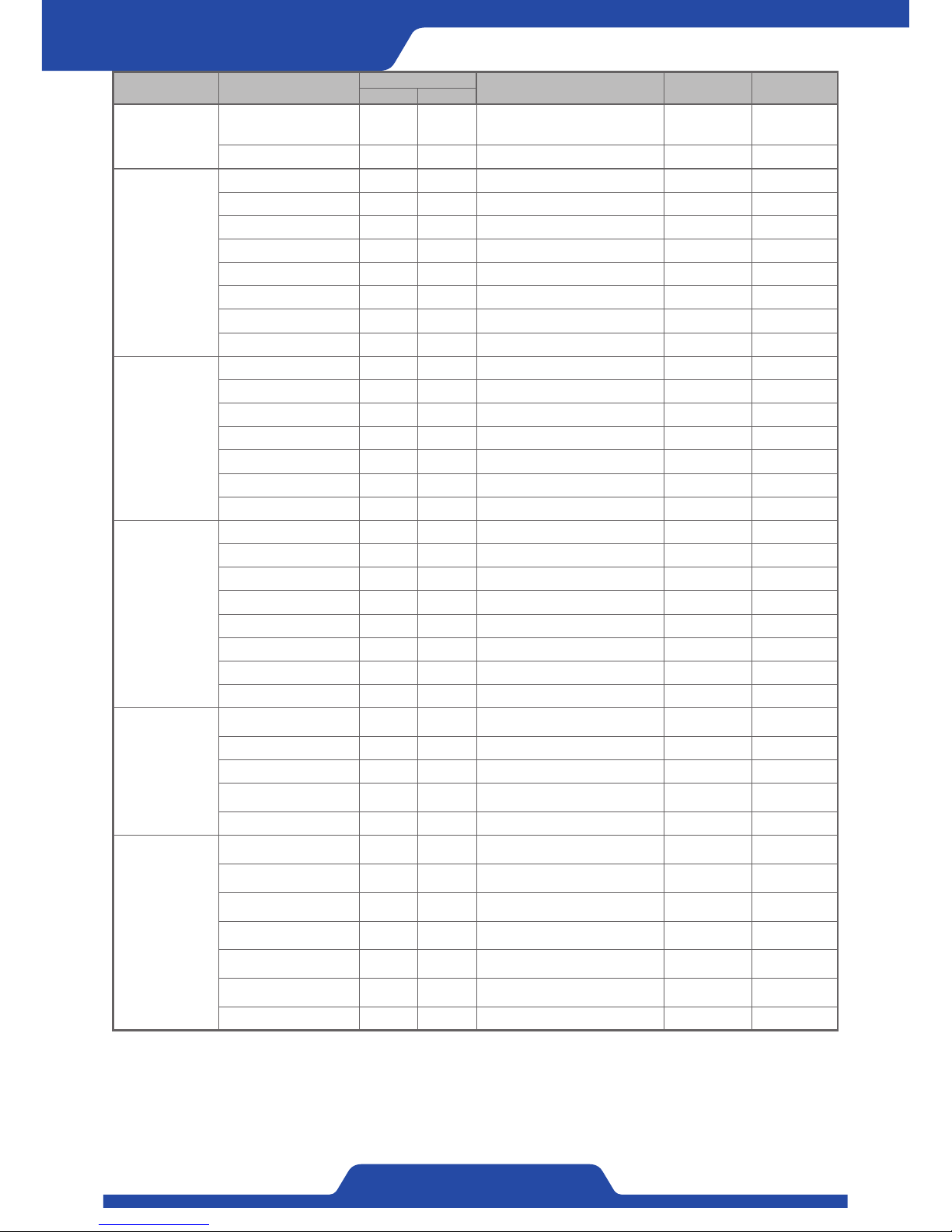
44
PORA ELECTRIC MACHINERY CO.,LTD.
Tension Controller
Setting menu item Submenu item
Modbus address
Setting range (Setting item) Initial setting Setting values
Int Hex
6. ANALOG
INPUT SEL.
5. ANALOG 3 40055 9C77
UNUSE, TENSION, TORQUE,
LINESPEED, DIAMETER,
DANCEDR ROLL
UNUSE
6. ANALOG 3 INPUT 40056 9C78 0...10V, 4...20mA 0...10V
7. ANALOG
INPUT SET
1. REF.ZERO(BCD) 40061 9C7D 0~16383 0
2. REF.SPAN(BCD) 40062 9C7E 0~16383 16383
3. OFFSET(%) 40063 9C7F 0.0~100.0 0.0
4. SPAN(xN) 40064 9C80 0.0~10.0 1.0
5. TRQ.ZERO(BCD) 40065 9C81 0~16383 0
6. TRQ.SPAN(BCD) 40066 9C82 0~16383 16383
7. OFFSET(%) 40067 9C83 0.0~100.0 0.0
8. SPAN(xN) 40068 9C84 0.0~10.0 1.0
8. LINESPEED
1. LINESPEED INPUT 40071 9C87 TG, ANALOG TG
2. SPEED MIN(mpm) 40072 9C88 0.0~1000.0 0.0
3. SPEED MIN(BCD) 40073 9C89 0~16383 0
4. SPEED MAX(mpm) 40074 9C8A 0.0~1000.0 200.0
5. SPEED MAX(BCD) 40075 9C8B 0~16383 16383
6. M/A MODE CHANGE 40076 9C8C UNUSE, USE UNUSE
7. CHANGE REF.(mpm) 40077 9C8D 0.0~1000.0 15.0
9. TAPER
1. DIAMETER INPUT 40081 9C91 PULSE, ANALOG ANALOG
2. THICKNESS(um) 40082 9C92 0.0~2000.0 100.0
3. REEL PULSE 40083 9C93 1, 2, 4, 8 1
4. TAPER RATIO(%) 40084 9C94 0.0~100.0 100.0
5. DIAMETER MIN(mm) 40085 9C95 0.0~2000.0 100.0
6. DIAMETER MIN(BCD) 40086 9C96 0~16383 0
7. DIAMETER MAX(mm) 40087 9C97 0.0~2000.0 1000.0
8. DIAMETER MAX(BCD) 40088 9C98 0~16383 16383
10. ANALOG
OUTPUT
1. CONTROL OUTPUT 40091 9C9B
0...5V, 0...10V, -10...+10V,
4…20mA, 0...20mA
0...10V
2. CONTROL POLARITY 40092 9C9C NORMAL, REVERSE NORMAL
3. CONTROL LMT(% RO) 40093 9C9D 0.0~100.0 100.0
4. TENSION OUTPUT 40094 9C9E
0...5V, 0...10V,
4...20mA, 0...20mA
0...10V
5. TENSION POLARITY 40095 9C9F NORMAL, REVERSE NORMAL
11. DIGITAL
INPUT
1. DIGITAL 1 40101 9CA5
UNUSE, AUTO, MANU, OUT ON/OFF,
ZERO, EMS, CHANGE, DIA.RESET
AUTO
2. DIGITAL 2 40102 9CA6
UNUSE, AUTO, MANU, OUT ON/OFF,
ZERO, EMS, CHANGE, DIA.RESET
OUT ON/OFF
3. DIGITAL 3 40103 9CA7
UNUSE, AUTO, MANU, OUT ON/OFF,
ZERO, EMS, CHANGE, DIA.RESET
ZERO
4. DIGITAL 4 40104 9CA8
UNUSE, AUTO, MANU, OUT ON/OFF,
ZERO, EMS, CHANGE, DIA.RESET
EMS
5. DIGITAL 5 40105 9CA9
UNUSE, AUTO, MANU, OUT ON/OFF,
ZERO, EMS, CHANGE, DIA.RESET
CHANGE
6. DIGITAL 6 40106 9CAA
UNUSE, AUTO, MANU, OUT ON/OFF,
ZERO, EMS, CHANGE, DIA.RESET
DIA.RESET
7. INPUT TYPE 40107 9CAB HOLD, PULSE HOLD
Page 47
45
PORA ELECTRIC MACHINERY CO.,LTD.
PR-DTC-4100.A / AD
Setting menu item Submenu item
Modbus address
Setting range (Setting item) Initial setting Setting values
Int Hex
12. DIGITAL
OUTPUT
1. DIGITAL 1 40111 9CAF
AUTO, MANU, OUT ON/OFF, ZERO,
EMS, A/B, TENSION HI, TENSION
LOW, SENSOR ERR, TENSION ERR,
DIAMETER MAX
AUTO
2. DIGITAL 2 40112 9CB0
AUTO, MANU, OUT ON/OFF, ZERO,
EMS, A/B, TENSION HI, TENSION
LOW, SENSOR ERR, TENSION ERR,
DIAMETER MAX
MANU
3. DIGITAL 3 40113 9CB1
AUTO, MANU, OUT ON/OFF, ZERO,
EMS, A/B, TENSION HI, TENSION
LOW, SENSOR ERR, TENSION ERR,
DIAMETER MAX
OUT ON/OFF
4. DIGITAL 4 40114 9CB2
AUTO, MANU, OUT ON/OFF, ZERO,
EMS, A/B, TENSION HI, TENSION
LOW, SENSOR ERR, TENSION ERR,
DIAMETER MAX
ZERO
5. DIGITAL 5 40115 9CB3
AUTO, MANU, OUT ON/OFF, ZERO,
EMS, A/B, TENSION HI, TENSION
LOW, SENSOR ERR, TENSION ERR,
DIAMETER MAX
SENSOR ERR
6. DIGITAL 6 40116 9CB4
AUTO, MANU, OUT ON/OFF, ZERO,
EMS, A/B, TENSION HI, TENSION
LOW, SENSOR ERR, TENSION ERR,
DIAMETER MAX
TENSION ERR
13. FILTER
1. TENSION(sec) 40121 9CB9 0.1~10.0 1.0
2. ANALOG IN(sec) 40122 9CBA 0.1~10.0 0.3
3. ANALOG OUT(sec) 40123 9CBB 0.1~10.0 0.3
14. USER SET
1. OUTPUT HOLD 40131 9CC3 UNUSE, TENSION, LINESPEED UNUSE
2. REF.TENSION(% FS) 40132 9CC4 0.0~100.0 10.0
3. REF.SPEED(mpm) 40133 9CC5 0.0~1000.0 10.0
4. HOLD TIME(sec) 40134 9CC6 0.0~100.0 3.0
5. HOLD RATIO(%) 40135 9CC7 0.0~1000.0 100.0
6. EMS TIME(sec) 40136 9CC8 0.0~100.0 3.0
7. EMS RATIO(%) 40137 9CC9 0.0~1000.0 100.0
8. BUZZER 40138 9CCA UNUSE, USE USE
15. DISPLAY
1. TENSION DISPLAY 40141 9CCD TOTAL, LEFT, RIGHT TOTAL
2. DECIMAL POINT 40142 9CCE 1, 0.1, 0.01 0.1
3. L OFFSET(% FS) 40143 9CCF 0.0~100.0 0.0
4. L SPAN(xN) 40144 9CD0 0.0~10.0 1.0
5. R OFFSET(% FS) 40145 9CD1 0.0~100.0 0.0
6. R SPAN(xN) 40146 9CD2 0.0~10.0 1.0
7. BRIGHTNESS(%) 40147 9CD3 10.0~100.0 80.0
8. OUTPUT DISPLAY 40148 9CD4 %, V %
INPUT
Master
-> Slave (PORA)
Exclusive use for
writing
REMOTE INPUT 40191 9CFF Refer to Fieldbus Interface -
Target tension 40192 9D00 0~20000 [1kg, 1N] -
MANUAL OUTPUT 40193 9D01 0~1000 [0.1%] -
LINESPEED 40194 9D02 0~10000 [0.1mpm] -
DIAMETER 40195 9D03 0~20000 [0.1mm] -
OUTPUT
Slave (PORA)
-> Master
Exclusive use for
reading
Status output 40196 9D04 Refer to Fieldbus Interface -
TOTAL TENSION 40197 9D05 -20000~20000 [1kg, 1N] -
LEFT TENSION 40198 9D06 -20000~20000 [1kg, 1N] -
RIGHT TENSION 40199 9D07 -20000~20000 [1kg, 1N] -
CONTROL OUTPUT 40200 9D08 0~1000 [0.1%] -
1. Data setting using communication does not support data type for Float. Please set ‘int type’ which multiplies 10
from current data for all read/write of Float type data.
2. When setting data, please input only within relevant setting range.
※Caution
Page 48
46
PORA ELECTRIC MACHINERY CO.,LTD.
Tension Controller
2. Checking abnormalities
Consumables which have short-term life are not equipped with this product. However, please check the below
regularly.
1) If the internal temperature is too high because of a heating element, direct right and etc?
2) If an alien substance and electric conductive particles are mixed inside?
3) If there is a loosening of connecting and terminal or else?
Item Symptom Response
Power
related
Controller does not
work.
1. Please check if the power voltage 100~240Vac and also the connection is right.
2. Please check if the foreign substance is inflowed.
3. Please check if the load is connected well.
4. Please contact PORA if there is a problem to power system inside a product.
HEALTH LED in front
part is off.
Please remove all electric connections except for power and contact PORA if same things
happened again.
Abnormality
of output
Control output dose not
generate.
1. Please check if the set-up output figures and real figures are matched.
2. Please check if the load at the terminal is connected well.
3. Please check current output setting (A.B shaft) and if it is connected to the shaft which
would be controlled.
4. Please check Fuse(7A) because it may be disconnection to Fuse due to overload.
Control output is shaken
severely in automatic
mode.
1. Please set P.I.D sensitivity to adjust the speed of output.
2. Please check if the tension is shaken.
Abnormality
of tension
Tension values are
shaken severely.
1. Please check if the setting is matched with a tension detecting sensor which would be
used.
2. Please check if tension calibration is done well and do re-calibrate.
3. Please check if ground connection is done well.
4. Please check if a tension detector has a problem.
Tension value does not
change.
1. Please check if the setting is matched with a tension detecting sensor which would be
used.
2. Please check if a tension detecting sensor is connected well.
3. Please check if tension calibration is done well and do re-calibrate.
4. Please check if a tension detecting sensor has a problem.
Abnormality
of operation
Buttons at front panel
do not work.
1. Please check in advance that button lock function and LED at the top of [lock button]
are on and an icon indicating lock function in LED display is shown.
2. Please check an icon in LCD display to see if remote function is activated to be hold
input.
Remote input does not
work.
1. Please check if remote input is activated. (Checking Remote LED)
2. Please check communication function (Modbus Ethernet) is being used.
3. Please check the input setting which would be used is done well. (Hold, Pulse)
Alarm LED at the front
part is off.
Please check the history table of alarm and if relevant alarm operation is right.
※If other symptoms besides that or problem occur, please contact PORA. (+82-31-455-8183)
Page 49
47
PORA ELECTRIC MACHINERY CO.,LTD.
PR-DTC-4100.A / AD
·In case of a web laminated, please sum up the tension of each web and add again 0.018 kg/cm.
·As for aluminum wire, please calculate 1/2 to 2/3 from this value.
(15,000 psi = 103.42 MPa / 1 mil = 25.4 microns)
3. Table for standard of tension
Material English Metric
Paperboard
Weight
(points)
Tension
(lbs/lin.inch)
Weight
(g/m2)
Tension
(kg/cm)
8 3.0 105 0.54
12 4.0 157 0.72
15 4.5 196 0.90
20 5.5 260 1.26
25 6.5 326 1.62
30 8.0 391 1.98
Paper
(based on 3,000
Sq. foot ream)
15 0.40 25 0.135
20 0.50 30 0.180
30 0.75 50 0.270
40 1.25 65 0.360
60 2.00 100 0.540
80 3.00 130 0.720
Material English Metric
Tension (lbs/in/mil) Tension (kg/cm/micron)
Aluminum Foils 1.0 0.00703
Cellophanes 0.75 0.00527
Acetate 0.5 0.00352
Polyethylene 0.12 0.00084
Mylar (Polyester) 0.75 0.00527
Polypropylene 0.25 0.00176
Polystyrene 1.0 0.00703
Saran 0.15 0.00105
Vinyl 0.1 0.00070
Nylon 0.25 0.00176
Wax Paper 1.0 0.00703
Material English Metric
Copper Wire (15,000 psi) Tension (lbs) Tension (kg)
#16 (0.051 inches) 30.00 13.608
#20 (0.032 inches) 12.00 5.443
#24 (0.020 inches) 4.50 2.041
#28 (0.013 inches) 1.75 0.794
#30 (0.010 inches) 1.25 0.567
#34 (0.006 inches) 0.50 0.227
#36 (0.005 inches) 0.25 0.113
#40 (0.003 inches) 0.10 0.045
Page 50

MEMO
Page 51
1.Every purchaserofPora's productsis eligible forcomplimentary after-salesservicesfor anydefects orerrors
thatmayhaveoccurredunderthenormalconditionsofusefortheprescribedperiodoftime.
2.Pora'sproductsareguaranteedforoneyear(12months)fromthetimeofpurchase.
3.I f youwanttohaveyourservicedasperthiscertificate,pleasecontactyournearestdealerorPora'sheadoffice.
Provided,youareresponsibleforalltheexpensesthatmaybeincurredbysending,bringingortransportingthe
producttoyourdealerortous.
4.Youmaynotbeeligibleforourcomplimentaryservicesevenwithinthecomplimentaryserviceperiodunderthe
followingcases.
1)Troublesordamagescausedbythemishandlingorincorrectuseoftheproduct.
2)Troubles or damages causedbythe maintenance, modifications or disassemblingbyany other than our
designateddealersorPora'sheadoffice.
3)Troublesordamagescausebyfire,earthquakes,floods,thunderboltsorothernaturaldisasters.
4)Troubles ordamages causedby thedropping,shocks,excessivepressureandvibrations,dusts,sinking under
waterorotherimproperhandling.
5)TroublesordamagescausedbytheuseofotherexpendablesorpartsthantheregularonesapprovedbyPora.
6)Incanthepurchaserfailstopresentthiscertificateforservice.
7)Troublesordamagescausedbyotherproductsconnectedwiththeproduct.
8)I n casethiscertificateisnotfilledwithsuchdescriptionsasthepurchasedateandcompanyname(supplier),
orsuchdescriptionsincludingthepurchasedateareeitherforgedorfabricated.
5.This certificateshall notbeapplicabletothe parts(housing, glass,connectors,etc.)orexpendables (oil,filter,
fuse,lamp,etc.)
6.Pora shallnotbe responsiblefor anydamages incidentaltothe troublesor damagesof theproduct.(expenses
incurred ortheloss of profits due tothemissed use of theproduct,orthe damages to otherdevicesthat
replacedPora'sproduct)
7.Pora'sproductshavegonethroughextensiveprecisionmanufacturingprocessesandtests,andanyerrorsforthe
productsrangingfrom±1to2mmshallnotconstituteanyrequestforthereplacementoftheproduct.
President & CEO:
Jung Kweon Kim
■ Thank you purchasing this product.
■ This certificate guarantees our complimentary after-sales services for our products
■ Please keep this certificate properly as we may reject to offer complimentary services if you fail to present this certificate to us.
Terms of Quality Assurance
Service Certificate
Customer
Name Company
Telephone E-mail
Address
Dealer
Name Telephone
Address
Product Name
Purchase Date
Problem
Hohfwulf#pdfklqhu|#Fr1/#Owg1
Page 52
www. por a. com
PORA ELECTRIC MACHINERY CO.,LTD.
Electric Machinery Co., Ltd.
www.pora.com
As to the latest information, please refer to the Website of Pora.
1. The content of this manual may be changed without prior notice, for which we request your kind understanding.
2. Be sure to read the catalog and user manual of each product before use.
3. Please accurately send a request for product specification, and check the content.
TEL: +82-31-455-8183, FAX: +82-31-457-8183
Product Purchase Inquiry
Head Office
13, LS-ro 166beon-gil, Gunpo-si, Gyeonggi-do, Korea
E-Mail
●Representative: [email protected]
●General Affairs Department: [email protected]
●Domestic: [email protected]
●International Trade-Overseas: [email protected]
 Loading...