

Populas Infinity 4836GT, Infinity 7236, Infinity 6648, Infinity Command Center 6040CR, Infinity Command Center 7234 Assembly Instructions Manual
Page 1
ASSEMBLY INSTRUCTIONS
ASSEMBLY INSTRUCTIONS
INFINITY MULTA SERIES
INFINITY
WORKSTATIONS, DESKS, AND TABLES WITH POWERED ADJUSTMENT
Workstations, desks, and tables with powered adjustment
ASSEMBLY INSTRUCTIONS
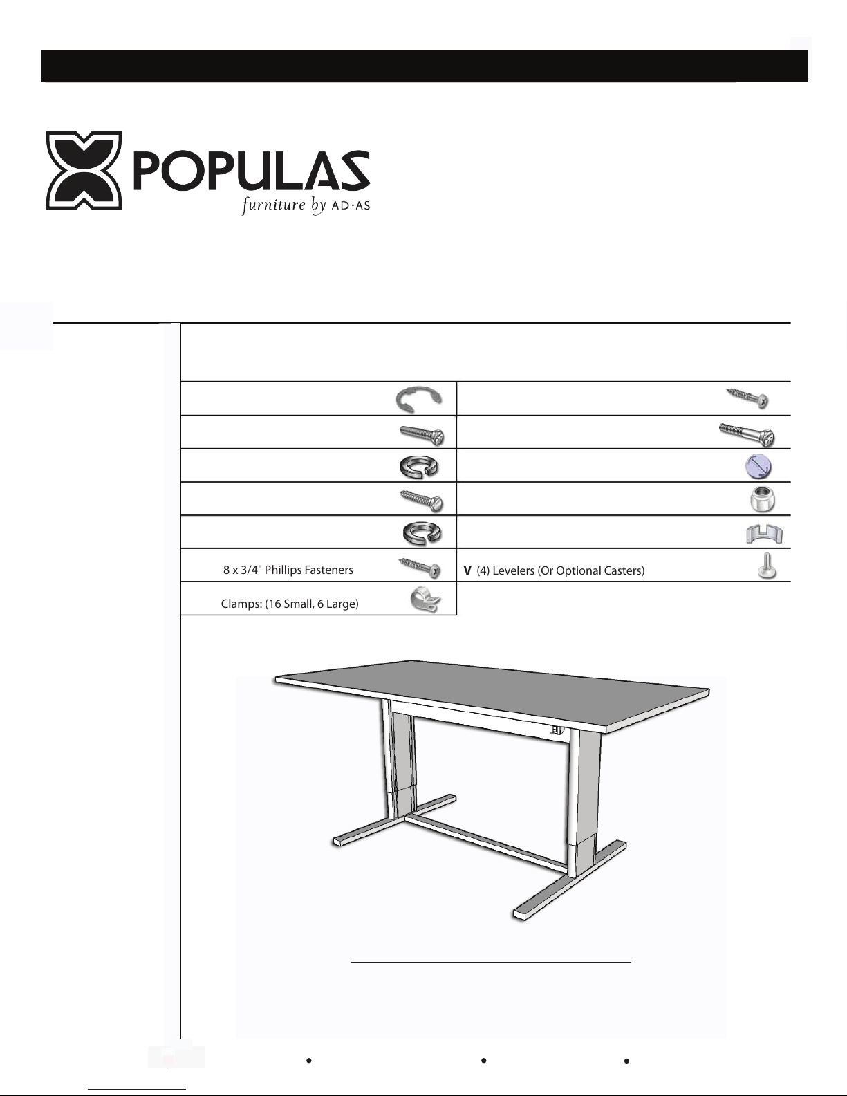
PARTS INCLUDED:
LEG PACKAGE:
A
(2) Telescoping
Legs
B
(1) Motor Assembly
C
(1) Control Box
D
(1) Control Switch
E
(1) Hardware bag
TABLE PACKAGE:
(1) Table Support
F
Brace
(1) Table Top
G
(1) Foot Brace
H
(1) Cross Brace with
I
Hardware
TOOLS NEEDED:
Phillips Screwdriver
Slotted Screwdriver
7/16” Open Ended
Wrench
1/2” Socket Wrench
7/32” Hex Key Wrench
(For optional Casters)
HARDWARE BAG WITH:
J (2) 1/2" Retaining Rings
K (8) 5/16"-18 x 1" Hex Head Fasteners
L (8) 5/16" Spring Washers
M (4) 1/4" x 1" Hex Head Lag Fasteners
N (4) 1/4" Spring Washers
O (9) #8 x 3/4" Phillips Fasteners
P (22) Clamps: (16 Small, 6 Large)
Q (22) #6 x 1/2" Phillips Fasteners
R (2) 1/4"- 20 x 2" Hex Head Cap Fasteners
S (2) Curved Connector Caps
T (2) 1/4"- 20 Nylon Insert Stop Nuts
U (2) Connector Plates
V (4) Levelers (Or Optional Casters)
2720 West Idaho Street Boise, ID 83702 Toll Free 800-957-2720 Fax 208-362-8009 www.populasfurniture.com
These instructions apply to the following models:
Innity 4836GT
Innity 7236
Innity 6648
Innity Command Center 6040CR
Innity Command Center 7234
Page 2
Step 1: Preparation
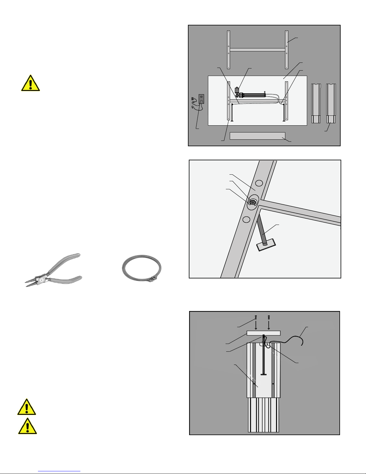
Unpack and identify all parts. Place Table Top (G)
upside down on padded surface and identify front
edge.
Be careful not to damage the hydraulic hose
Step 2: Piston Attachment
Insert hydraulic piston into center hole of Table
Support Brace (F) with piston top recessed inside
brace. Secure with 1/2" Retaining Ring (J), using pliers
to snap Retaining Ring into piston groove. Repeat for
second piston. Snap ring pliers and snap rings can be
used. Pull on piston to secure attachment.
Long Hose
Control Box
and Switch
Table Brace
Table Brace
Piston Head
Snap Ring
Motor Assembly
Front Edge
Foot Brace
Table Top
Short Hose
Telescoping Legs
Cross Brace
Piston
Snap ring pliers
Snap rings
Step 3: Telescoping Leg
Attachment
Insert piston foot into center of Telescoping Leg (A).
Piston hose port must route through "mouse hole"
of Telescoping Leg (A). Align Telescoping Leg (A) with
hose port facing center. Attach using two
5/16" -18 x 1" Hex Head Fasteners (K) and 5/16" Spring
Washers (L). Tighten using a 1/2" socket wrench. Do
not completely tighten until Step 4. Repeat for
second leg.
Slotted groove on Telescoping Leg Faces in
Hex Head Fasteners
Table Brace
Piston
Telescoping Leg
Piston Hose
Mouse Hole
Keep hose routed through mouse hole to
avoid pinch points
Page 3
Step 4: Foot Brace Attachment
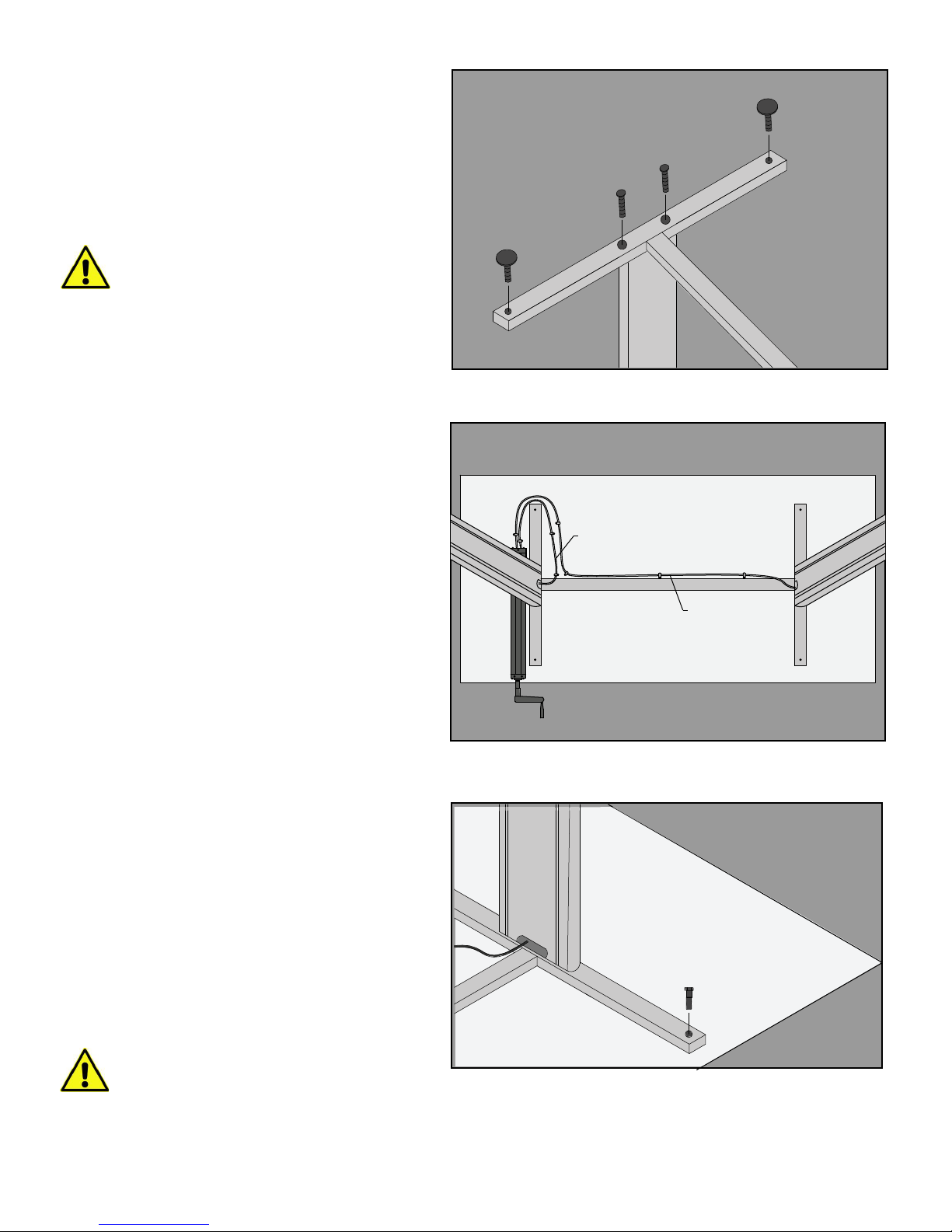
Attach Foot Brace (H) to Telescoping Legs
(A) using two 5/16”-18 x 1” Hex Head
Fasteners (K) and 5/16”Spring Washers (L)
for each Telescoping leg (A), with Fastener
heads recessed inside Foot Brace (H).
Now tighten the four 5/16”-18 x 1”
Hex Head Fasteners from Step 3
Attach Floor Levelers (V). Optional Casters
attach using 3/8” button head fasteners.
Step 5: Hand-crank Assembly
Positioning
Short Hose
Place Hand-crank Assembly (B) on table
as shown.
Step 6: Table Support Brace
Attachment
Place Table Support Brace (F) and Motor
Assembly (B) on underside of table. Locate
three guide holes for Motor Assembly (B).
Position Telescoping Leg (A) with shorter
hose (A, Right). Align Table Support Brace (F)
to guide holes and attach using four 1/4" x 1"
Hex Head Fasteners (M) and 1/4" Spring
Washers (N). Tighten using 7/16” socket
wrench.
Long Hose
Front Edge
Do not over-tighten or strip
Page 4
Step 7: Motor Attachment
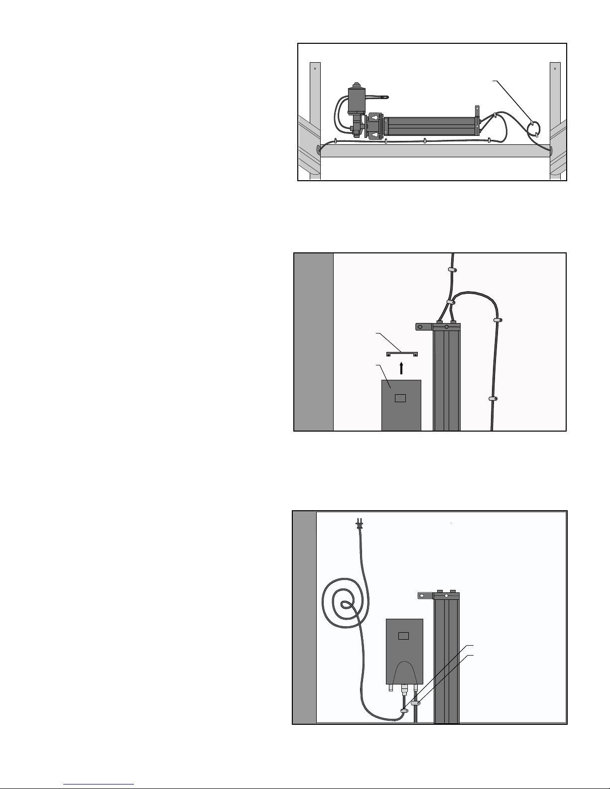
Align Motor Assembly (B) to three pre-drilled
holes and attach using three #8 x 3/4" Phillips
Fasteners (O). Route hoses through Small
Clamps (P) in pattern shown, and secure using
#6 x 1/2" Phillips Fasteners (Q).
Step 8: Control Box Attachment
Remove clip from Control Box (C) and attach
to the table (number side down) using two
#8 x 3/4” Phillips Fasteners (O). Carefully slide
Control Box (C) onto clip and fasten the
Control Box to pre-drilled holes using two
#8 x 3/4" Phillips Fasteners (O).
Small Clamps
Clip
Control Box
Step 9: Motor Placement
Plug motor wire into Control Box (C). Secure wires
with two Large
Fasteners (Q). Plug power wire into Control Box (C).
Secure one Small
#6 x 1/2” Phillips fasteners (Q).
Clamps (P) using #6 x 1/2" Phillips
Clamp (P) (for strain relief) using
Small Clamps
Large Clamps
Page 5
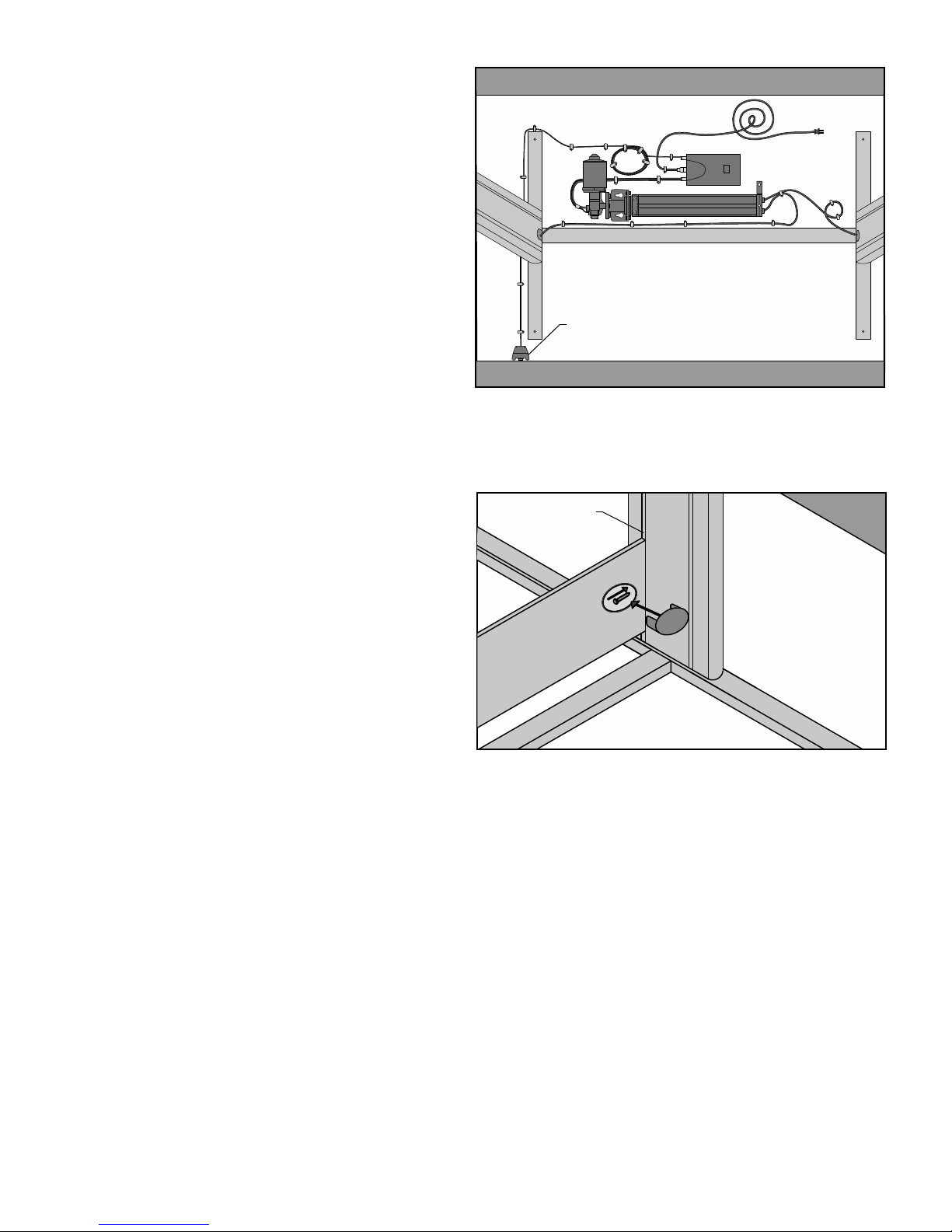
Step 10: Control Switch
Attachment
Attach Control Switch (D) to pre-drilled location
using two # 8 x 3/4" Phillips Fasteners (O). Control
Switch (D) may be positioned elsewhere depending
upon preference. Secure wire with Small Clamps (P)
and #6 x 1/2" Phillips Fasteners (Q). Insert Control
Switch (D) plug into Control Box. Coil the wire and
secure with four Large Clamps (P) using #6 x 1/2"
Phillips Fasteners (Q).
Control Switch
Rear Slotted Groove
Step 11: Cross Brace Attachment
Hardware is shipped attached. Insert 1/4”-20 x 2”
Hex Head Fasteners (R) into rear slotted groove of
Telescoping Leg (A). Level Cross Brace (H) below
top of Telescoping Leg. Tighten using 7/16" wrench.
Cover connector hardware with Connector Cap (S).
Step 12: Operation And Use
Gently turn table over and adjust levelers if required.
Table adjusts up and down using the control switch.
Clean with soft cloth and mild cleaners suitable for
furniture.
 Loading...