

Page 1
1
Solar Powered Outdoor Siren
Manual
005107
Page 2

2
Solar Powered Outdoor Siren – Manual
Quick Start .............................................................................................................................. 2
Product Description ................................................................................................................ 2
Installation Guidelines ............................................................................................................ 3
Behavior within the Z-Wave Network...................................................................................... 3
Operating the Device .............................................................................................................. 4
Node Information Frame ......................................................................................................... 4
Associations ........................................................................................................................... 4
Configuration Parameters ....................................................................................................... 4
Command Classes ................................................................................................................. 6
Technical Data ....................................................................................................................... 6
Explanation of Z-Wave specific Terms ................................................................................... 7
Disposal Guidelines ................................................................................................................ 7
Support ................................................................................................................................... 7
Quick Start
This device is a Z-Wave actuator. The device usually comes precharged. In case there is
not enough power please place the device into sun light for 10 minutes.
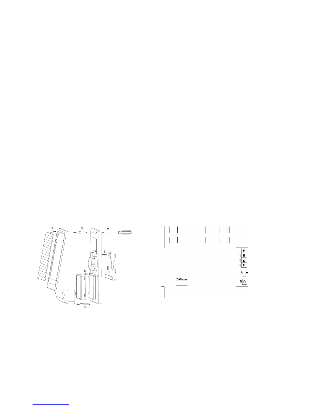
1. Open the case and turn on the power switch (ill.2 (A)) by moving it towards the
inclusion button (B). All LEDs will shine for a short moment to confirm.
2. Remove the metal mounting plate from the device.
3. Remove all protection foil from the device.
4. Turn your controller into inclusion mode with a short single click on the internal
inclusion button (ill.2 (B)).
The device supports secure communication if the controller supports secure communication
as well. Keeping the inclusion button pushed for 2 seconds includes the device unsecured
regardless of the controller’s capabilities. Once the siren is placed on the metal mounting
plate the tamper protection is activated. Do not remove the siren anymore unless it is
deactivated!
Product Description
This solar powered outdoor siren can be used without any additional power supply or
batteries. It can be installed on any place on the outside of the house and can be controlled
using Z-Wave. The device will issue a very loud sound (105 dBm) and in parallel some
stroboscope light as well. The siren is self-protecting. Removing the main device from the
mounting unit immediately starts the siren and also reports the tamper attempt to the ZWave central controller. All communication between the Z-Wave controller and the siren is
Page 3
3
encrypted and secured to protect against manipulation. Thanks to the large solar panel the
siren can be mounted on nearly every place outside the house, with direct or indirect sun
light. The siren is maintenance-free and water-proofed (IP56). The average solar energy of
one day keeps the device alive for up to 50 days (without using the siren). Additionally an
internal temperature sensor reports the temperature inside the siren’s enclosure.
Installation Guidelines
The siren can be placed on every location outside the home. Thanks to rating IP56 the
location does not even need to be dry but please make sure it is placed high enough so that
children do not accidently remove it. The device is self-protected against tamper and theft. In
a first step the mounting plate (ill. 1 (1)) is placed on the wall using the 4 screws provided. It is
recommended to mount the complete device 5 mm from the wall for better sound.
1. Open the case and turn on the power switch (ill.2 (A)) by moving it towards the
inclusion button (B). All LEDs will shine for a short moment to confirm.
2. Remove the metal mounting plate from the device.
3. Remove all protection foil from the device.
4. Turn your controller into inclusion mode with a short single click on the internal
inclusion button (ill.2 (B)).
Once included the enclosure of the siren is closed using the 6 screws. Finally the siren is
placed on the mounting plate.
Attention: As soon as the siren is placed on the mounting plate the tamper protection is
activated. The siren must not be removed from the plate anymore. The behavior in this
moment is defined by the configuration parameter No 1.
Behavior within the Z-Wave Network
On factory default the device does not belong to any Z-Wave network. The device needs to
join an existing wireless network to communicate with the devices of this network. This
(A) Power Button
(B) Inclusion Button
(C) Battery Connection
ill. 1
ill. 2
(D) Solar Module Connection
(E) Charge Connection
(F) Speaker Connection
Page 4

4
process is called Inclusion. Devices can also leave a network. This process is called
Exclusion. Both processes are initiated by the primary controller of the Z-Wave network.
This controller will be turned into exclusion respective inclusion mode. Please refer to your
primary controller’s manual on how to turn your controller into inclusion or exclusion mode.
Only if the primary controller is in inclusion or exclusion mode, this device can join or leave
the network. Leaving the network – i.e. being excluded – sets the device back to factory
default.
Operating the Device
The siren can be turned on and off using wireless commands. To protect this communication
from misuse is strongly recommended to operate the siren in secure communication mode.
The secure communication is activated on default during inclusion unless explicitly
suppressed. When activated the siren will generate a 105 dB alarm sound and a flash light.
This behavior can be configured as well using configuration parameter 5. Make sure to
deactivate the tamper protection before removing an included siren from the mounting plate.
Back to Factory Default
To reset the device keep the inclusion button pushed for 10 seconds. After 5 seconds the
LED starts flashing and after another 5 seconds there is a short beep signaling the
successful reset back to factory defaults. Use this procedure only when the network primary
controller is missing or otherwise inoperable.
Node Information Frame
The Node Information Frame is the business card of a Z-Wave device. It contains
information about the device type and the technical capabilities. The inclusion and exclusion
of the device is confirmed by sending out a Node Information Frame. Beside this it may be
needed for certain network operations to send out a Node Information Frame.
Every click on the inclusion button (ill. 2 (B)) issues a Node Information Frame.
Associations
Z-Wave devices control other Z-Wave devices. The relationship between one device
controlling another device is called association. In order to control a different device, the
controlling device needs to maintain a list of devices that will receive controlling commands.
These lists are called association groups and they are always related to certain events
(e.g. button pressed, sensor triggers, ...). In case the event happens all devices stored in the
respective association group will receive a common wireless command.
Associations
1
Lifeline (max. nodes in group: 10)
Configuration Parameters
Z-Wave products are supposed to work out of the box after inclusion, however certain
configuration can adapt the function better to user needs or unlock further enhanced
features.
Page 5

5
IMPORTANT: Controllers may only allow configuring signed values. In order to set values in
the range 128… 255 the value sent in the application shall be the desired value minus 256.
For example: to set a parameter to 200 it may be needed to set a value of 200 minus 256 =
minus 56. In case of a two byte value the same logic applies: Values greater than 32768
may needed to be given as negative values too.
Siren triggering mode (Parameter Number 1, Size 1)
Sets the tamper triggering mode when removed from the holder
Value
Description
0
The Siren triggers automatically when it's removed from the holder. Must be
turned off, using the button or from the controller (Default)
1
The Siren triggers automatically when it's removed from the holder and turns off,
when placed back on the holder
2
Siren doesn't trigger at all, when removed from the holder. Service Mode
Temperature adjustments (Parameter Number 2, Size 1)
Temperature correction. For positive value 10 = 1 °C, for negative value x = 256 - (T°C * 10).
Example, if need shift -2.6°C, value calculate: 256 - (2.6 * 10) = 230.
Value
Description
0
Disabled (Default)
1 – 127
In 0.1°C (Default 0)
128 – 255
-0.1°C
Send unsolicited temperature report (Parameter Number 3, Size 1)
Threshold temperature to send unsolicited report. 10 = 1°C
Value
Description
0 – 255
In 0.1°C (Default 10)
Send unsolicited temperature report after N wake up (Parameter Number 4, Size 2)
If the value is set, after N wake up number (measurement is every 4 minutes) the
temperature report will be sent. By default it's 15 = every 1 hour
Value
Description
0
Disabled
1 – 65535
Each Nth wake up time (Default 15)
Switch mode: siren only, flash only, flash + siren (Parameter Number 5, Size 1)
Value
Description
0
Siren only
1
Flash only
2
Flash + Siren (Default)
Page 6

6
Added Auto OFF (Parameter Number 6, Size 1)
If the value is set, the siren will be switched off automatically after a defined alarm time.
Value
Description
0
No auto off
1-…
Minutes (Default 5)
Command Classes
Supported command classes
BASIC
Version 1
DEVICE RESET LOCALLY
Version 1
Z-WAVE PLUS INFORMATION
Version 2
MANUFACTURER SPECIFIC
Version 2
POWERLEVEL
Version 1
FIRMWARE UPDATE META DATA
Version 3
BATTERY
Version 1
VERSION
Version 2
SECURITY
Version 1
BINARY SWITCH
Version 1
BINARY SENSOR
Version 2
MULTILEVEL SENSOR
Version 5
ASSOCIATION GROUP INFORMATION
Version 1
CONFIGURATION
Version 1
ALARM
Version 5
ASSOCIATION
Version 2
Technical Data
IP Rating
IP 56
Battery Type
1 * Solar/ Storage battery: 7.4 V, 2,300 mA
Frequency
868.42 MHz (SRD Band)
Wireless Range
Up to 100 m outside, on average up to 20 m inside buildings
Explorer Frame Support
No
Device Type
Slave with routing capabilities
Generic Device Class
Binary Switch
Routing
No
FLiRS
No
Firmware Version
1.0
Page 7

7
Explanation of Z-Wave specific Terms
• Controller is a Z-Wave device with capabilities to manage the network. Controllers are
typically gateways, remote controls or battery operated wall controllers.
• Slave is a Z-Wave device without capabilities to manage the network. Slaves can be
sensors, actuators and even remote controls.
• Primary Controller is the central organizer of the network. It must be a controller. There
can be only one primary controller in a Z-Wave network.
• Inclusion is the process of bringing new Z-Wave devices into a network.
• Exclusion is the process of removing Z-Wave devices from the network.
• Association is a control relationship between a controlling device and a controlled device.
• Wake up Notification is a special wireless message issued by a Z-Wave device to
announce that is able to communicate.
• Node Information Frame is a special wireless message issued by a Z-Wave device to
announce its capabilities and functions.
Disposal Guidelines
The product contains batteries. Please remove the batteries when the device is not used.
Do not dispose of electrical appliances as unsorted municipal waste, use separate collection
facilities. Contact your local government for information regarding the collection systems
available. If electrical appliances are disposed of in landfills or dumps, hazardous
substances can leak into the groundwater and get into the food chain, damaging health and
well-being.
Support
Should you encounter any problem, please give us an opportunity to address it before
returning this product. Most questions regarding Z-Wave wireless communication standard
can be answered through the international community at www.z-wave.info.
If your question can‘t be answered there, please contact us by email: info@popp.eu
Page 8

8
© 2015 POPP & Co.
While the information in this manual has been compiled with great care, it may not be deemed an
assurance of product characteristics. Popp & Co. shall be liable only to the degree specified in the terms
of sale and delivery.
The reproduction and distribution of the documentation and software supplied with this product and the
use of its contents is subject to written authorization from Popp & Co. We reserve the right to make any
alterations that arise as the result of technical development.
Phone: +44 (0) 20 7419 5726
eMail: info@popp.eu
Web: www.popp.eu
 Loading...