

Page 1
Popp
POPP Wall Controller 2
SKU: POPE700861
Quickstart
This is a Z-Wave Device for Europe. To run this device please connect it to your mains power supply. On factory default state pushing any button for one
seconds starts inclusion (red/green LED blinking fast). This behavior can be used to test the factory default or exclusion state.
What is Z-Wave?
Z-Wave is the international wireless protocol for communication in the Smart Home. This device is suited for use in the region mentioned in the Quickstart section.
Z-Wave ensures a reliable communication by reconfirming every message (two-way communication) and
every mains powered node can act as a repeater for other nodes (meshed network) in case the receiver is
not in direct wireless range of the transmitter.
This device and every other certified Z-Wave device can be used together with any other certified
Z-Wave device regardless of brand and origin as long as both are suited for the same frequency range.
If a device supports secure communication it will communicate with other devices secure as long as this
device provides the same or a higher level of security. Otherwise it will automatically turn into a lower level
of security to maintain backward compatibility.
For more information about Z-Wave technology, devices, white papers etc. please refer to www.z-wave.info.
Product Description
The Popp Wall Controller is a Z-Wave device that can both control other Z-Wave devices and activate predefined scenes in an IP gateway. Although it is
controlling other devices, the Wall Controller cannot act as Z-Wave network controller (primary or secondary) and will always need a Z-Wave network controller to
be included into a Z-Wave network. The device can be used in different modes that are selected by configuration parameters:
1. Control of groups of other Z-Wave devices using "ON", "OFF" and Dim commands.
2. Activation of predefined scenes in Gateways or other Z-Wave devices.
The wall controller must be completed by a mounting frame, the wall switch frame and a rocker. They are not scope of delivery of this device.
This device support secure communication when included by a controller that also supports secure communication. The device will then send all commands as
secure commands unless the receiving device can not accept them. Then the command is send the normal way automatically.
The device will be completed with different designs of wall frame and rockers.
For example:
• Berker (S.1, B.1, B.3, B.7 Glass),
• GIRA (System 55, Standard 55, E2, E22, Event, Esprit),
• Merten (1-M, Atelier-M, M-Smart, M-Arc, M-Star, M-Plan),
• Schneider Electric Exxact,
• Jung (A 500, AS 500, A plus, A creation)
• Kopp HK07
Prepare for Installation / Reset
Please read the user manual before installing the product.
In order to include (add) a Z-Wave device to a network it must be in factory default state. Please make sure to reset the device into factory default. You can do
this by performing an Exclusion operation as described below in the manual. Every Z-Wave controller is able to perform this operation however it is recommended
to use the primary controller of the previous network to make sure the very device is excluded properly from this network.
Reset to factory default
This device also allows to be reset without any involvement of a Z-Wave controller. This procedure should only be used when the primary controller is inoperable.
The device can be set back to factory defaults without performing an exclusion process. Please executes the following steps: (1) Turn the device into Management
Mode, (2) click on Button 3, (3) keep button 4 pushed for 4 seconds.
Page 2
Safety Warning for Mains Powered Devices
ATTENTION: only authorized technicians under consideration of the country-specific installation guidelines/norms may do works with mains power. Prior to the
assembly of the product, the voltage network has to be switched off and ensured against re-switching.
Installation
The device can be mounted on every dry and flat surface using either screws or double side adhesive. First the mounting base is fixed on the wall. Next step the
switch frame is placed on the 2 frame and the electronic insert is used to fix the frame to the mounting base as shown on the image. Finally the switching paddle(s)
are mounted on the electronic base.
For battery change, the switching paddle(s) need to be removed. The CR battery can be replaced by pushing the little nipple above the battery. The old battery will
slide out and the new battery is inserted until the nipple will hold it again.
The device can be operated in two different modes:
• Operation Mode: This is the mode where the device is controlling other Z-Wave devices or is activating scenes.
• Management Mode: The device is turned into the management mode by pushing all four buttons for 5 sec. A blinking green LED indicates the
management mode. In the management mode the buttons of the device have different functions. If no further action is performed, the device will turn back
to the normal mode after 10 sec. Any management action terminates the management mode as well.
In management mode the following actions can be performed:
• Button 1 - Re-Inclusion/Exclusion: Every re-inclusion or exclusion attempt is confirmed by hitting this button. Any button press stops the mode as well.
• Button 2 - Send Node Information Frame and Wake up Notification. (see explanation below)
• Button 3 - Factory Default Reset. After clicking on button 3 keep button 4 pushed for >4 seconds
• Button 4 - Enter into Association mode to assign target devices to one of the four association. Refer to the manuals section about association for more
information how to set and unset association groups.
Inclusion/Exclusion
On factory default the device does not belong to any Z-Wave network. The device needs to be added to an existing wireless network to communicate with the
devices of this network. This process is called Inclusion.
Devices can also be removed from a network. This process is called Exclusion. Both processes are initiated by the primary controller of the Z-Wave network. This
controller is turned into exclusion respective inclusion mode. Inclusion and Exclusion is then performed doing a special manual action right on the device.
Product Usage
Depending on the button mode and operating modes configured using the configuration parameters the key fob can be used in different ways.
Button modes:
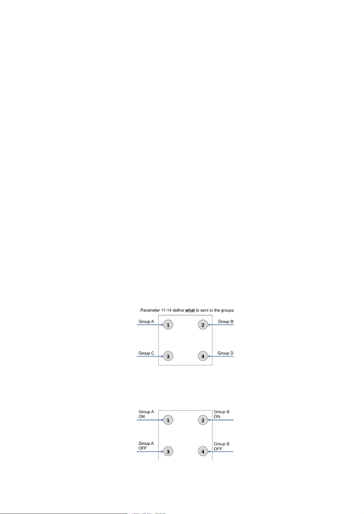
4 Groups are controlled with single button (parameter 1/2 = 0) The four buttons 1-4 control one single control group each: 1->A, 2->B, 3->C, 4->D. Single click
turns devices in the control group on, double click turns them off. Click and hold can be used for dimming.
2 Groups are controlled with two buttons (parameter 1/2 = 1) The buttons 1 and 3 control the control group A (button on turns on, buttons turns off), the
buttons 2 and 4 control the control group B (button on turns on, buttons turns off). In case dimmers are controlled, holding down the larger button will dim up,
holding down the smaller button will dim down the load. Releasing the button will stop the dimming function.
4 Groups are controlled with two buttons and double click (parameter 1/2 = 2) This mode enhances the previous mode and allows to control two further
control groups C and D using double clicks.
Page 3

Operating modes:
The devices supports 8 different operating modes - this means the kind of command sent out when pushing a button. Operating modes either directly control other
devices or they issue various scene activation commands to a central controller. Operating modes for direct device control are:
• Direct Control of associated devices with On/Off/Dim commands (parameter 11...14 = 1). Devices are controlled using Basic Set On/Off commands
and SwitchMultilevel Dim Start/Stop. This mode implements communication pattern 7.
• Direct Control of associated devices with only On/Off commands (parameter 11...14 = 2). Devices are controlled using only Basic Set On/Off
commands. On dimming Up event On is sent, on dimming Down Off is sent. This mode also implements communication pattern 7.
• Switch All commands (parameter 11...14 = 3) In this mode a all neighbouring devices will receive SwitchAll Set On/Off command and interpret it
according to their membership in SwitchAll groups. This mode implements communication pattern 7.
• Door Lock Control (parameter 11...14 = 7) This modes allows direct control (open/close) of electronic door locks using secure communication. The mode
implements communication pattern 7.
Operating modes for scene activation are:
• Direct Activation of preconfigured scenes (parameter 11...14 = 5) Associated devices in an association group are controlled by individual commands
defines by Z-Wave command class ?Scene Controller Configuration?. This mode enhances mode Direct Control of associated devices with On/Off/Dim
commands and implements communication patterns 6 and 7. Please turn the button mode to "seperate" to allows different scene id on every button.
• Scene Activation in IP Gateway (parameter 11...14 = 4) If configured correctly the buttons can trigger a scene in a gateway. The scene number triggered
is a combination of the group number and the action performed on the button and has always two digits. The group number defines the upper digit of the
scene number, the action the lower digit. The following actions are possible:
• 1 = On
• 2 = Off
• 3 = Dim Up Start
• 4 = Dim Down Start
• 5 = Dim Up Stop
• 6 = Dim Down Stop
Example: Clicking/double clicking the button will issue scene triggers, scene 11 (button 1 click, event on), scene 12 (button double click 1, event off, single
button control is used in this example)
• Activation of Central Scenes (parameter 11...14 = 8,Default) Z-Wave Plus introduces a new process for scene activation - the central scene control.
Pushing a button and releasing a button sends a certain command to the central controller using the lifeline association group. This allows to react both on
button push and button release. This mode implements communication patterns 6 but requires a central gateway supporting Z-Wav Plus.
Node Information Frame
The Node Information Frame (NIF) is the business card of a Z-Wave device. It contains information about the device type and the technical capabilities. The
inclusion and exclusion of the device is confirmed by sending out a Node Information Frame. Beside this it may be needed for certain network operations to send
out a Node Information Frame. To issue a NIF execute the following action:
Pressing Button 2 in management mode will issue a Node Information Frame.
Quick trouble shooting
Here are a few hints for network installation if things dont work as expected.
1. Make sure a device is in factory reset state before including. In doubt exclude before include.
2. If inclusion still fails, check if both devices use the same frequency.
3. Remove all dead devices from associations. Otherwise you will see severe delays.
4. Never use sleeping battery devices without a central controller.
5. Dont poll FLIRS devices.
6. Make sure to have enough mains powered device to benefit from the meshing
Association - one device controls an other device
Z-Wave devices control other Z-Wave devices. The relationship between one device controlling another device is called association. In order to control a different
device, the controlling device needs to maintain a list of devices that will receive controlling commands. These lists are called association groups and they are
always related to certain events (e.g. button pressed, sensor triggers, ...). In case the event happens all devices stored in the respective association group will
receive the same wireless command wireless command, typically a 'Basic Set' Command.
Page 4

Association Groups:
Group Number Maximum Nodes Description
1 10 Lifeline
2 10 Control Group A
3 10 Control Group B
4 10 Control Group C
5 10 Control Group D
Configuration Parameters
Z-Wave products are supposed to work out of the box after inclusion, however certain configuration can adapt the function better to user needs or unlock further
enhanced features.
IMPORTANT: Controllers may only allow configuring signed values. In order to set values in the range 128 ... 255 the value sent in the application shall be the
desired value minus 256. For example: To set a parameter to 200 it may be needed to set a value of 200 minus 256 = minus 56. In case of a two byte value the
same logic applies: Values greater than 32768 may needed to be given as negative values too.
Parameter 1: Button 1 and 3 pair mode
In separate mode button 1 works with Group A, button 3 with Group C. Click is ON, Hold is dimming UP, Double click is OFF, Click-Hold is dimming DOWN. In pair
button 1/3 are UP/DOWN correspondingly. Click is ON/OFF, Hold is dimming UP/DOWN. Single clicks works with Group A, double click with Group C.
Size: 1 Byte, Default Value: 1
Setting Description
0 Separately
1 In pair without double clicks
2 In pair with double clicks
Parameter 2: Button 2 and 4 pair mode
In separate mode button 2 works with control group B, button 4 with control group D. Click is ON, Hold is dimming UP, Double click is OFF, Click-Hold is dimming
DOWN. In pair button B/D are UP/DOWN correspondingly. Click is ON/OFF, Hold is dimming UP/DOWN. Single clicks works with Group B, double click with
Group D.
Size: 1 Byte, Default Value: 1
Setting Description
0 Separately
1 In pair without double clicks
2 In pair with double clicks
Parameter 11: Command to control Group A
This parameter defines the command to be sent to devices of control group A when the related button is pressed.
Size: 1 Byte, Default Value: 8
Setting Description
0 Disable
1 Switch on/off and Dim (send Basic Set and Switch Multilevel)
2 Switch on/off only (send Basic Set)
3 Switch all
4 Send scenes
5 Send preconfigured scenes
6 Control devices in proximity
7 Control door lock
8 Central scene to gateway (default)
Parameter 12: Command to control Group B
This parameter defines the command to be sent to devices of control group B when the related button is pressed.
Size: 1 Byte, Default Value: 8
Page 5

Setting Description
0 Disable
1 Switch on/off and Dim (send Basic Set and Switch Multilevel)
2 Switch on/off only (send Basic Set)
3 Switch all
4 Send scenes
5 Send preconfigured scenes
6 Control devices in proximity
7 Control door lock
8 Central scene to gateway (default)
Parameter 13: Command to control Group C
This parameter defines the command to be sent to devices of control group C when the related button is pressed.
Size: 1 Byte, Default Value: 8
Setting Description
0 Disable
1 Switch on/off and Dim (send Basic Set and Switch Multilevel)
2 Switch on/off only (send Basic Set)
3 Switch all
4 Send scenes
5 Send preconfigured scenes
6 Send preconfigured scenes
7 Control door lock
8 Central scene to gateway
Parameter 14: Command to control Group D
This parameter defines the command to be sent to devices of control group D when the related button is pressed.
Size: 1 Byte, Default Value: 8
Setting Description
0 Disable
1 Switch on/off and Dim (send Basic Set and Switch Multilevel)
2 Switch on/off only (send Basic Set)
3 Switch all
4 Send scenes
5 Send preconfigured scenes
6 Control devices in proximity
7 Control door lock
8 Central scene to gateway (default)
Parameter 21: Send the following switch all commands
Size: 1 Byte, Default Value: 1
Setting Description
1 Switch off only
2 Switch on only
255 Switch all on and off
Parameter 22: Invert buttons
Size: 1 Byte, Default Value: 0
Page 6

Setting Description
0 No
1 Yes
Parameter 25: Blocks wake up even when Wake Up Interval is set
If the KFOB wakes up and there is no controller nearby, several unsuccessful communication attempts will drain battery.
Size: 1 Byte, Default Value: 0
Setting Description
0 Wake up is blocked
1 Wake up is possible if configured accordingly
Parameter 30: Send unsolicited battery report on Wake Up
Size: 1 Byte, Default Value: 1
Setting Description
0 No
1 To same node as Wake Up Notification
2 Broadcast to neighbors
Technical Data
Dimensions 80 x 80 x 18 mm
Weight 30 gr
Hardware Platform ZM5202
EAN 4251295700861
IP Class IP 20
Voltage 3V
Battery Type 1 * CR2032
Explanation of Z-Wave specific terms
• Controller — is a Z-Wave device with capabilities to manage the network. Controllers are typically Gateways,Remote Controls or battery operated wall
controllers.
• Slave — is a Z-Wave device without capabilities to manage the network. Slaves can be sensors, actuators and even remote controls.
• Primary Controller — is the central organizer of the network. It must be a controller. There can be only one primary controller in a Z-Wave network.
• Inclusion — is the process of adding new Z-Wave devices into a network.
• Exclusion — is the process of removing Z-Wave devices from the network.
• Association — is a control relationship between a controlling device and a controlled device.
• Wakeup Notification — is a special wireless message issued by a Z-Wave device to announces that is able to communicate.
• Node Information Frame — is a special wireless message issued by a Z-Wave device to announce its capabilities and functions.
(c) 2019 Z-Wave Europe GmbH, Antonstr. 3, 09337 Hohenstein-Ernstthal, Germany, All rights reserved, www.zwave.eu. The template is maintained by Z-Wave
Europe GmbH. The product content is maintained by Z-Wave Europe GmbH , Supportteam, support@zwave.eu. Last update of the product data: 2018-06-01
10:19:18
 Loading...