

Page 1

POP_004407
CO Detector
Firmware Version : 1.0
Quick Start
S
This device is a wireless Z-Wave sensor. Exclusion, Inclusion are confirmed by hitting the programm
button for 1 sec when the sensor is removed from the mounting ring and the tamper switch is released. A
wakeup is performed hitting the programm button for 1 sec when the sensor is not removed from the
mounting ring and the tamper switch is not released.
Please refer to the chapters below for detailed information about all aspects of the products usage.
Product description
Carbon Monoxide is the most toxic substance people can come into contact with in their daily lives: at home,
at work, garage, car, caravan or boat. You can't see or smell carbon monoxide, but at high levels it can
poison a person in minutes. Carbon monoxide (CO) is produced whenever any fuel such as gas, oil,
kerosene, wood or charcoal is burned. If appliances that burn fuel are maintained and used properly, the
amount of CO produced is usually not hazardous. However, if appliances are not working properly or are
used incorrectly, dangerous levels of CO can result. Hundreds of people die accidentally every year from
CO poisoning caused by malfunctioning or improperly used fuel-burning appliances. Even more die from CO
produced by idling cars. Fetuses, infants, elderly people and people with anemia or with a history of heart or
respiratory disease can be especially susceptible. The concentration of this gas is measured in ppm (parts
per million) and is approximately 0.1 ppm in the atmosphere. In residential buildings the normal
concentration is 0.5 to 5 ppm. In the vicinity of gas burners e.g. concentrations of up to 15 ppm may occur.
The device will send an alarm when one of the following conditions are met:
50 ppm for 60 minutes
100 ppm for 10 minutes
300 ppm for 3 minutes
Popp Carbon Monoxide Combi Sensor is a new solution for advanced Carbon Monoxide (CO) detection in
households and businesses. This model has compact, yet spacious and stylish housing to also complies to
the Z-Wave wireless protocol. The performance of the device is enhanced by Japanese-made Nemoto
electrochemical CO sensor. The Popp CO Combi Sensor measures the CO concentration in the air and
issues an alarm when a certain level of CO is exceeded. Beside the main function of detecting Carbon
Page 2
Monoxide the device also reports and monitors the ambient temperature and humidity, which can
additionally be used for the identification of smouldering. According to the directive DIN EN14604 the CO
sensor gives a visual warning and the alarm siren occurres when a high CO concentration is measured. This
siren has a defined volume of 85dB at a distance of 3 meters. The device is easy to install and easy for
professional installers to open for cleaning. A lock prevents the installation of the device without battery. The
automatic self-calibration and self-test increase the reliability of the device. After the installation a manual
system test can be done by pushing the key button on the device. The CO detector has a wireless
connection to the Z-Wave network. The measured values of the temperature sensor, the humidity sensor
and the current battery level can be read out by a Z-Wave controller. A regular status report of the sensor
enables a comfortable centralized management of many devices. It generates different alarm signals that
either are received and evaluated by a central Z-Wave controller or can control switching actions of other ZWave devices (e.g. turning on/ off the light) directly:
Fire alarm (displayed locally by light and audio)
Battery level warning, when the battery power level drops below 20% (shown locally by light and short audio)
Tamper protection if the device is removed from the bracket
Fall above or below a temperature range (thresholds can be programmed wirelessly via Z-Wave)
Fall above or below a humidity range (thresholds can be programmed wirelessly via Z-Wave)
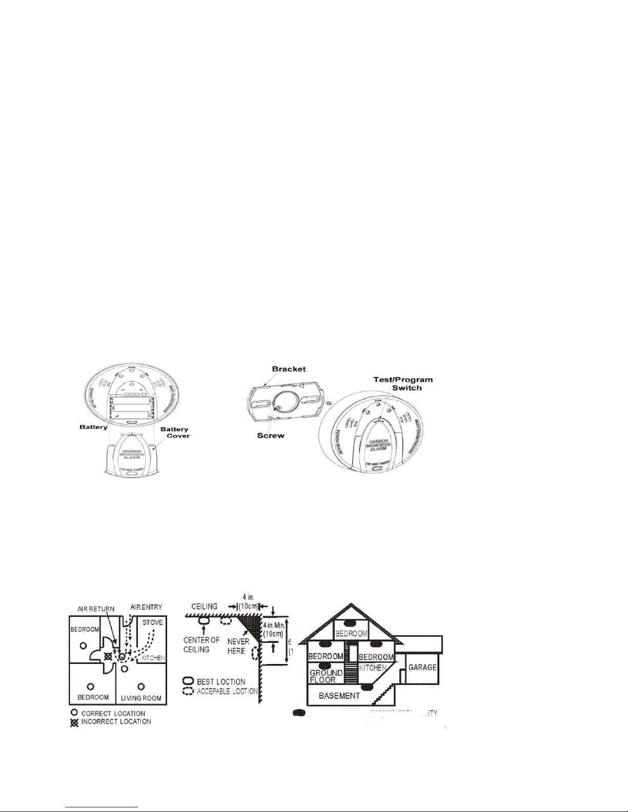
Installation Guidelines
1.
Remove the bracket from the detector by rotating it counter-clockwise.
2.
Place the bracket where you are going to install the detector. In each of keyhole slots, draw a mark to
locate plastic anchor and screw. Using a 3/16-inch (5mm) drill bit, drill two holes at the marks and
insert plastic anchor, and attach the bracket by using the screws.
3.
Open the battery cover to insert the batteries, and then replace the cover. Fix the detector with
bracket by rotating it clockwise.
Please follow the recommendations about amount and position of the sensor in your home as given above.
Avoid to place the sensor into the angle of walls, prefer positions in the middle of the room.
Page 3

Behavior within the Z-Wave network
I
On factory default the device does not belong to any Z-Wave network. The device needs to join an
existing wireless network to communicate with the devices of this network. This process is called Inclusion.
Devices can also leave a network. This process is called Exclusion. Both processes are initiated by the
primary controller of the Z-Wave network. This controller will be turned into exclusion respective inclusion
mode. Please refer to your primary controllers manual on how to turn your controller into inclusion or
exclusion mode. Only if the primary controller is in inclusion or exclusion mode, this device can join or leave
the network. Leaving the network - i.e. being excluded - sets the device back to factory default.
If the device already belongs to a network, follow the exclusion process before including it in your network.
Otherwise inclusion of this device will fail. If the controller being included was a primary controller, it has to
be reset first.
Exclusion, Inclusion are confirmed by hitting the programm button for 1 sec when the sensor is removed
from the mounting ring and the tamper switch is released.
Operating the device
Power-on Mode: 1) Install the battery into the module 2) The detector will emit a beep in 0.5 seconds and
the three LEDs will flash once quickly. 3) Close the bracket. The CO detector will alarm once remove the
bracket.
Stand-by Mode: The Green LED flashes one time every 60 seconds.
Alarm Mode (It is the status when the alarm is triggered.): If a certain density of CO is detected, an audible
alarm with 4 beeps, pause 5 seconds and 4 beeps will occure. The red LED will flash continuously and
rapidly. Meanwhile, the CO detector will send an alarm report (type: CO alarm, state: alarm) to the user’s
controller and also the CO dectecor will send an alarm report (type: CO alarm, state: No alarm) while the
alarm goes off.
Error Mode: If the CO detector beeps once and yellow LED flashes three times every minute, it indicates
the CO detector is not working properly. Please require to repair or service.
Low battery warning Mode: The yellow LED will flash once every minute with a "beep" sound.
Low sensitivity Mode: The yellow LED will flash twice every minute with a "beep" sound. It indicates the
CO detector has internal problem, please replace the unit.
Tamper Mode: The yellow LED will go solid and the detector will emit a short beep every minute until the
CO detector is mounted back to the bracket properly.
End of life signal Mode: The yellow LED will flash four times every minute with a short "beep" sound. It
indicates the CO detector is reaching to the end of useful life, please replace with a new unit.
Testing Mode: Test the alarm by pushing test switch until the user hears 4 short beeps and three LEDs
flash synchronously in five seconds. Then, the CO detector will send an alarm report (type: CO alarm, state:
alarm) to the user’s controller and also the CO detector will send an alarm report (type: CO alarm, state: No
alarm) while the alarm goes off. Please note if the CO detector only beeps once and yellow LED flashes
three times every minute, it indicates the CO detector is not working properly. Please require to repair or
service.
Battery Power indicator: The detector will report the current status of battery capacity to the user’s
controller.
Page 4

Self-Protection Mode: If the cover of detector removed from bracket, after 8 sec the detector will send an
alarm report (type:0*02, level:0*FF) to the Z-Wave Interface Controller and the yellow LED will flash
continuously and the detector will sound.
Silence Mode: The user could press the test switch to get into silence mode to turn off the alarm temporarily
when the CO detector alarms. Meanwhile, the red LED will flash continually. The silence function will
automatically turn into normal operation if the CO concentration around the CO detector is still at alarming
level after 4 minutes of silence mode.
WARNING: The carbon monoxide sensing unit has only 5-year limited life. For the security issue, we
strongly recommend the user to change whole the CO detector after 4-year usage.
Wakeup Intervals - how to communicate with the device?
W
This device is battery operated and turned into deep sleep state most of the time to save battery
life time. Communication with the device is limited. In order to communicate with the device, a static
controller C is needed in the network. This controller will maintain a mailbox for the battery operated devices
and store commands that can not be received during deep sleep state. Without such a controller,
communication may become impossible and/or the battery life time is significantly decreased.
This device will wakeup regularly and announce the wakeup state by sending out a so called Wakeup
Notification. The controller can then empty the mailbox. Therefore, the device needs to be configured with
the desired wakeup interval and the node ID of the controller. If the device was included by a static
controller this controller will usually perform all necessary configurations. The wakeup interval is a tradeoff
between maximal battery life time and the desired responses of the device.
A wakeup is performed hitting the programm button for 1 sec when the sensor is not removed from the
mounting ring and the tamper switch is not released.
It is possible to set the node ID to 255 to send wakeup notifications as broadcast. In this mode device takes more time to
go to sleep and drains battery faster, but can notify all it's direct neighbors about a wakeup.
Node Information Frame
NI
The Node Information Frame is the business card of a Z-Wave device. It contains information
about the device type and the technical capabilities. The inclusion and exclusion of the device is confirmed
by sending out a Node Information Frame. Beside this it may be needed for certain network operations to
send out a Node Information Frame.
Hitting the program button will send out an Node Information Frame
Associations
Page 5

A
Z-Wave devices control other Z-Wave devices. The relationship between one device controlling
another device is called association. In order to control a different device, the controlling device needs to
maintain a list of devices that will receive controlling commands. These lists are called association groups
and they are always related to certain events (e.g. button pressed, sensor triggers, ...). In case the event
happens all devices stored in the respective association group will receive a common wireless command.
Association Groups:
1 Controller, all Temperature and Humidity Changes (max. nodes in group: 5)
2 Switches Device when temperature reaches trigger level (max. nodes in group: 5)
4 Switches device when smoke was detected (max. nodes in group: 5)
Configuration Parameters
Z-Wave products are supposed to work out of the box after inclusion, however certain configuration can
adapt the function better to user needs or unlock further enhanced features.
IMPORTANT: Controllers may only allow to configure signed values. In order to set values in the range 128
… 255 the value sent in the application shall be the desired value minus 256. For example: to set a
parameter to 200? it may be needed to set a value of 200 minus 256 = minus 56. In case of two byte value
the same logic applies: Values greater than 32768 may needed to be given as negative values too.
Send Unsolicited temperature report (Parameter Number 1, Parameter Size 1) Threshold temperature to
send unsolicited report. 10 = 1 °C
Value Description
0 Disabled (Default)
5 — 50 0.1 °C
Temperature shift (Parameter Number 2, Parameter Size 1) Threshold correction. For positive value 10 = 1
°C, for negative value x = 256 - (T°C * 10). Example, if need shift -2°C, value calculate: 256 - (2 * 10) = 236.
Value Description
0 Disabled (Default)
1 — 127 0.1 °C
127 — 255 0.1 °C
Page 6

Inverts Switching Command on Association Group 2 (Parameter Number 5, Parameter Size 1)
Value Description
0 At High send ON (Default)
255 At High send OFF
Inverts Switching Command on Association Group 4 (Smoke) (Parameter Number 7, Parameter Size 1)
Value Description
0 on Smoke send ON (Default)
255 on Smoke send OFF
Send SensorBinary- Report to Group 1 (Parameter Number 8, Parameter Size 1) When Smoke is detected
a Sensor Binary Report is sent out to Association Group 1
Value Description
255 Send Alarm Smoke
0 Send Sensor Binary Report (Default)
Temperatur Trigger Low Value (Parameter Number 9, Parameter Size 1) Needs parameter ?1 to be set.
Sets the temperature Low value, if the measurement is lower than this value, Basic OFF is sent in
temperature association group(2). 255 -disable
Value Description
255 Disabled (Default)
0 — 100 °C
Temperatur Trigger High Value (Parameter Number 10, Parameter Size 1) Needs parameter ?1 to be set.
Sets the temperature High value, if the measurement is higher than this value, Basic ON is sent in
temperature association group(2)
Value Description
255 Disabled (Default)
0 — 100 °C
Page 7

Technical Data
Battery Type 1 * CR123A
Explorer Frame Support Yes
SDK 4.55.00
Device Type Slave with routing capabilities
Generic Device Class Alarm Sensor
Specific Device Class Routing Smoke Sensor
Routing No
FLiRS No
Firmware Version 1.0
 Loading...