

Page 1
Electric Strike Lock Control
Manual
012501
Quick Start
This device is a Z-Wave actuator. Pressing the “Z-Wave button” 3 times in 1 second (includes) and removes (excludes) the
device from/to the Z-Wave network.
Please refer to the chapters below for detail ed information about all aspects of the product.
1
Page 2
LED
Z-Wave
You have to install the mechanical
Product Description
An electric strike is an access control device used to lock and release doors. Electric strikes are installed in or on the doorframe
and work in conjunction with mechanical door locks, on the principle of electronically controlling the rotation of the keeper.
Allowing for door opening without manual retraction of the mechanical door lock. This product combines a 16 mm thick strike
lock (that will fit into almost all door formats) with a Z-Wave plus empowered wireless control.
The lock mechanics and the Z-Wave control are operated by a 9V block battery or an external 8-12V AC / 8-24V DC
transformer. The Z-Wave control accepts commands to open or close the strike. Depending on a configuration parameter the
door will be looked automatically after a certain time even if no ‘close’ command was sent. According to t he connected Z-Wave
Gateway all actions of the Strike Lock will be recorded with a time stamp.
The device is a secure Z-Wave Plus device and ca n be used in one wireless Z-Wave network with other certified devices
regardless of origin and brand. It supports secure communication if the central controller supports secure communication as
well.
Installation Guidelines
The Strike-Lock has a IP 20 protection class. Because of that it is not recommended to install the device directly outdoors.
Button
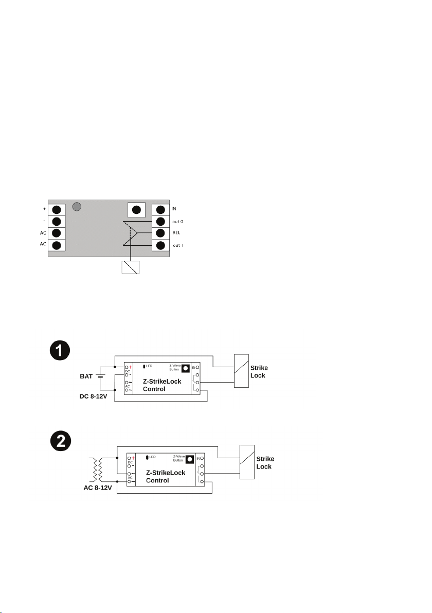
There 4 possible starting situations when you want to install the Strike-Lock:
No existing installation of an electrical door opener:
part first. Depending if there is an
existing electrical transformer or the
door opener will be battery powered
you refer to picture 1 or 2.
The strike lock can be installed:
- next to electrical transformer
- behind the mechanic doorl ock
- between those mentioned parts
2
Page 3
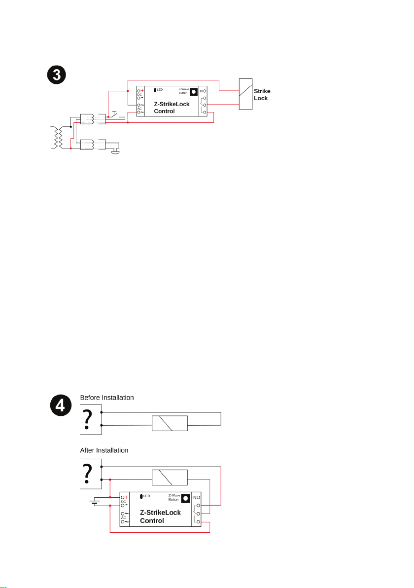
Analog Installation
There is already an existing door opener and a swi tch to control the door opener. Normally that is powered by an electrical
transformer. In that system a simple electric circuit exists. Switch and opener – refer to the picture. The electrical circuit can be
realized by two different options.
1. Cable from transformer to switch – cable from switch to lock – cable from cable to transformer
2. Pair of Cable from transformer to switch – pair of cable from transformer to lock
Connecting terminal at the transformer between a cable from the switch and a cable from the lock.
Both kinds of wiring are electrical identic. Both are possible and work properly. The more convenient solution is Version 2.
The Z-Wave Stricke Lock can be installed in all 3 positions depending on the available space. The electrical wiring is identical to
a new installation, but it could be necessary to install an additional cable to the switch or the lock. So that the mod ule is has
electricity – refer to picture 3.
Existing door intercom without door opener
In that case the installation equals a complete new installation of a doorlock. It is only possible that the existing transformer can
be used. The door lock control can be easily connected parallel to the transformer, if the transformer has the right output
voltage.
Look at picture ½
Existing intercom with door opener
The intercom with one or more participants is normally based on an internal communicationbussystem and a gateway or control
box, which is connected to the actual door ope ner. Here you have many different options for the installation. But for the
installation of the Strike-Lock that is not relevant. You just have to find both wires, which connect the control module with the
door lock mechanism. For that you just have to uninstall the existing doorlock or you refer to the information of the
vendor/installer, who has installed the intercom.
3
Page 4

1
Lifeline (max. nodes in group: 10)
2
Action on External Dry Input (max. nodes in group: 10)
Image 4 shows the necessary wiring. It is not relevant of you use a transformer or battery. One pol of the power supply (a) i s
connected with a cable from the doorlock. The ot her cable to the doorlock has to be cut and be connected to the terminals (out
0) and REL of the control module where the cabl e to the opener has to be connected to REL. After that change the Intercom will
work with the door opener as before. By of the two ope ned cables you can reset the default setting of the door control. As a last
step you have to connect the other pol of the power s upply with the terminal out 1 of the control module. After that the parallel
us of the intercom and the Z-Wave module is possi ble.
Now you can include the Strike Lock with pressing 3 times in 1 second on the Z-Wave button. Then you can set the
configuration over the gateway.
Behavior within the Z-Wave Network
On factory default the device does not belong to a ny Z-Wave network. The device needs to join an existing wireless network to
communicate with the devices of this network. This process is called Inclusion. Devices can also leave a network. This process
is called Exclusion. The primary controller of the Z-Wave network initiates both processes. This controller will be turned into
exclusion respective inclusion mode. Please refer to your primary controller’s manual on how to turn your controller into
inclusion or exclusion mode. Only if the primary controller is in inclusion or exclusion mode, this device can join or leave the
network. Leaving the network – i.e. being excluded – sets the device back to fact ory default.
If the device already belongs to a network, follow the exclusion process before including it in your network. Otherwise inclusion
of this device will fail. If the controller being included was a primary controller, it has to be reset first.
Pressing the Z-Wave button for one second includes the device. It is not allowed to operate the device in a non-secure
environment. This means that the including controller must support Secure Command Class. A single click on the button will
exclude the device.
Operating the Device
Sending secure wireless open command will release the lock until either the timeout kicks in nor a closed signal is sent. If you
want to operate a third party strike lock with dry monitor contact, you can connect them to the input pin. The status of the door is
then reported using sensor binary commands.
Factory Reset
To do a factory reset press the Z-Wave button o n the bottom of the device for at least 10 seconds. This procedure should only
be used when the primary controller is inoperable.
Firmware Update
Once the firmware update process has started double click the Z-Wave button to confirm firmware update process.
Some estimation on battery life
The strike lock control itself only needs about 20 mA of power. A 9 V lithium battery block will last more than 4 years. The
operation of a strike lock however costs energy. Just assume 5 operations over a period of 5 seconds per day in vibration mode
will drain the battery in about one year. Reduci ng the maximum on-time will even further reduce power consumption and
increase battery life time.
Node Information Frame
The Node Information Frame (NIF) is the business card of a Z-Wave device. It contains information about the device type a nd
the technical capabilities. The inclusion and exclusion of the device is confirmed by sending out a Node Information Frame.
Beside this it may be needed for certain network operations to send out a Node Information Frame.
A simple click on the Z-Wave button sends a NIF.
Associations
Z-Wave devices control other Z-Wave devi ces. The relationship between one device controlling another device is called
association. In order to control a different device, the controlling device needs to maintain a list of devices that will receive
controlling commands. These lists are called association groups and they are always related to certain events (e.g. button
pressed, sensor triggers, ...). In case the event happens all devices stored in the respective association group will receive a
common wireless command.
Association Groups
4
Page 5

Value
Description
0
No automated close after command ‘open’
1 - 127
Close again after x seconds (Default 3)
Value
Description
0 - 99
(Default 0)
Value
Description
0 - 99
(Default 99)
Battery Type
Transformer AC 8 -12 V / DC 8-24V or 9V Block
Frequency
868/869 MHz (SRD Frequency Band according EN300220)
Wireless Range
Up to 100 m outside, on average up to 40 m inside buildings
Explorer Frame Support
Yes
SDK
6.51.6
Device Network Role
Reachable Sleeping Slave (RSS)
Device Type
Sensor
Routing
Mesh Network: yes ; but no forwarding of other devices messages
Firmware Version
1.0
Power draw on battery
15 mA
Dimensions
61.8 x 16.5 x 25.5 mm
Weight
0.1 Kg
Max. operation temperature
300°C
Operating type
Fail Secure
Operating current (at 9V) for full pull
500 mA
Operating current (at 9V) for vibration
250 mA
Adjustable latch
3 mm
Certification
2004/108/CE (EN55014)
Configuration Parameters
Z-Wave products are supposed to work out of the box after inclusion, however certain configuration can adapt the function
better to user needs or unlock further enhanced features.
IMPORTANT: Controllers may only allow configuring signed values. In order to set values in the range 128 … 255 the value
sent in the application shall be the desired val ue minus 256. For example: to set a parameter to 200 it may be needed to set a
value of 200 minus 256 = minus 56. In case of a two-byte value the same logic applies: Values greater t han 32768 may needed
to be given as negative values, too.
Automated Close after Opening (Parameter number 0, Size 1).
Value of Off-Command (Parameter number 1, Size 1)
Value of On-Command (Parameter number 2, Size 1)
Technical Data
Technical Parameter
Lock Control
Strike Lock Mechanics
Support
Should you encounter any problem, please gi ve us an opportunity to address it before returning this product. Most questions
regarding Z-Wave wireless communication standard can be answered through the international community at www.z-
wave.info.If your question cannot be answered there, please use www.popp.eu/support or contact us by email: info@popp.eu
5
Page 6

Notes
6
Page 7

7
Page 8

© 2016 POPP & Co.
While the information in this manual has been compiled with great care, it may not be deemed an assurance of product characteristics. Popp & Co.
shall be liable only to the degree specified in the terms of sale and delivery. The reproduction and distribution of the documentation and software
supplied with this product and the use of its contents is subject to written authorization from Popp & Co. We reserve the right to make any alterations
that arise as the result of technical development.
Phone: +44 (0) 20 7419 5726
eMail: info@ popp.eu
Web: www.pop p.eu
8
 Loading...