

Page 1
1
Battery Wall Controller
Manual
009303
Page 2

2
Battery Wall Controller – Manual
Quick Start ........................................................................................................................................................................... 2
Product Description ............................................................................................................................................................. 3
Installation Guidelines ......................................................................................................................................................... 3
Behavior within the Z-Wave Network .................................................................................................................................. 4
Operating the Device........................................................................................................................................................... 5
Child Protection ................................................................................................................................................................... 6
Wake Up Intervals – How to communicate with the device ................................................................................................ 6
Node Information Frame ..................................................................................................................................................... 7
LED Control ......................................................................................................................................................................... 7
Associations ........................................................................................................................................................................ 7
Set and Unset Associations to Actuators ............................................................................................................................ 7
Special Functions as Z-Wave Controller ............................................................................................................................. 7
Configuration Parameters ................................................................................................................................................... 8
Command Classes ............................................................................................................................................................ 10
Technical Data .................................................................................................................................................................. 11
Explanation of Z-Wave specific Terms ............................................................................................................................. 11
Disposal Guidelines........................................................................................................................................................... 12
Support .............................................................................................................................................................................. 12
Quick Start
This remote control has two modes:
• Normal operation for daily use
• Management mode for setup
Pushing all four buttons for 1 sec. turns the device into management mode (indicated by slow blinking green LED).
Management mode time-out is 10 sec. In factory default mode pushing one of the four buttons for 1 sec will start
different inclusion modes:
• Button 1: Include (add) Wall Controller as secondary controller
• Button 2: Include (add) Wall Controller as secondary controller – non secure
• Button 3: Include (add) new device into Wall Controller network
• Button 4: Include (add) new device into Wall Controller network – non secure
The processes for button 1 and 2 is indicated with fast red/green blinking, the processes for button 3 and 4 shows a
fast green blinking. Every button push stops the process. This fast inclusion only works when device is in factory
default. Once one device is included or the Wall Controller is included as secondary controller further inclusion and
exclusion operation require to turn the device into management mode:
• Button 1: Include or exclude the device as secondary controller
• Button 2: Issue Wake Up Notification and send out Node Information Frame
• Button 3 followed by short click on button 1: Start secure inclusion
• Button 3 followed by short click on button 2: Start unsecure inclusion
• Button 3 followed by short click on button 3: Start exclusion
• Button 3 followed by short click on button 4: Start primary handover
Page 3
3
and only IF the Wall Controller is the primary controller of the
network. The first device included into a button group will define
the commands sent out by this group regardless of the default value of
the configuration parameters 11-14. If the device is a door lock the
button group will turn into door lock control (value=7). For dimmers and
motor controls the value changes into Multilevel Switch Control
(value=1). All other devices will turn the button group into Basic Control
(value=2). All configuration values can be changed if needed. When the
Wall Controller is primary controller the very first device included will
be automatically put into button group A and the command set will
change according to the rules just mentioned. All other devices need to
be put in button groups manually.
Product Description
The wireless Wall Controller is a 4 button Z-Wave device capable to act both as primary or secondary controller. The
four buttons can control other Z-Wave devices such as switches, dimmer and even door locks directly. Various
options – configurable by Z-Wave configuration commands – define the actions and the commands used for this
control. It is possible to use two sets of buttons (one for on/open/up and one for off/closed/down) or four single buttons
to control four different groups of devices.
The controller also allows triggering scenes in a central controller. Again different modes can be configured to
adapt to the various implementations of scenes in different central controllers in the market.
Control options also include special modes like „all on/off“ or always controlling the Z-Wave
device in proximity to the controller.
The device supports secure communication when included with enhanced security option
and when communicating to a device also supporting enhanced security option. Otherwise
the device will automatically turn into normal communication to maintain backward
compatibility.
Installation Guidelines
The device comes ready to use with a battery already installed. Just pull the plastic strip to activate the device. The
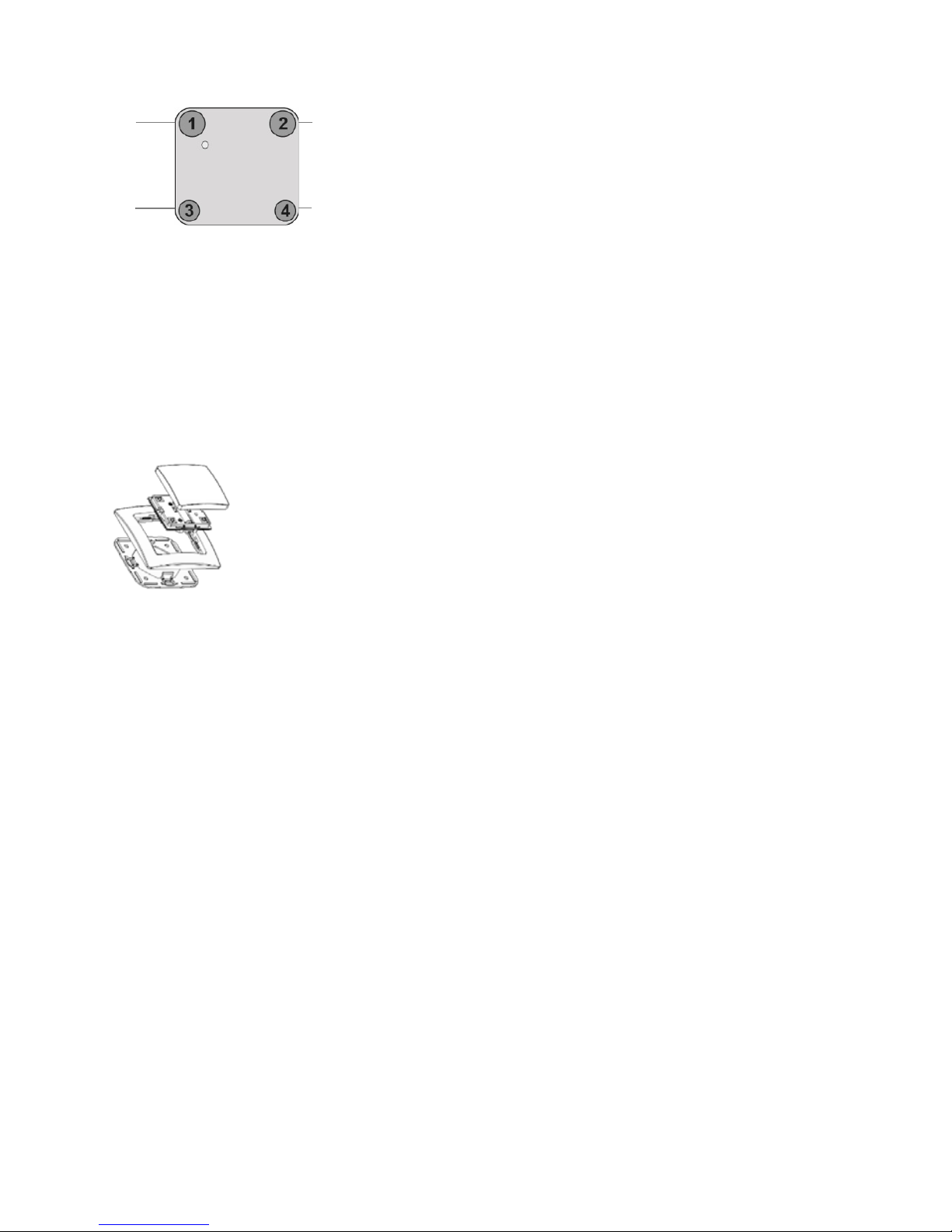
device can be mounted on every dry and flat surface using either screws or double side adhesive. First the mounting
base is fixed on the wall. Next step the switch frame is placed on the 2 frame and the electronic insert is used to fi x the
frame to the mounting base as shown on the image. Finally the switching paddle(s) are mounted on the electronic
base.
For battery change, the switching paddle(s) need to be removed. The CR battery can be replaced by pushing the little
nipple above the battery. The old battery will slide out and the new battery is inserted until the nipple will hold it again.
The device can be operated in two different modes:
• Operation mode: This is the mode where the device is controlling other devices.
• Management Mode: The device is turned into the management mode by pushing all four buttons for one second.
A blinking LED indicates the management mode. In the management mode buttons of the device have different
functions. If no further action is performed the device will turn back to the normal mode after 10 seconds. Any
management action terminates the management mode as well.
In management mode the following actions can be performed:
• Button 1 – Inclusion/Exclusion: Every inclusion or exclusion attempt is confirmed by hitting this button. Single click
is used for standard inclusion and exclusion, double click is used for network wide inclusion. With this operation
the device can be included into a Z-Wave network from any physical location in the network. This requires a
primary controller supporting network wide inclusion. This mode lasts for 20 seconds and stops automatically. Any
button press stops the mode as well.
• Button 2: Sends Node Information Frame and Wake Up Notification (see explanation below).
• Button 3: Activates the primary controller management menu. The following sub menu items are available:
Button 3 followed by short click on button 1: Start Secure Inclusion (Add)
Include
as s econ dary
secure
as
primary
secure
*
* If includ ed device supports s ecurity
as s econ dary
nor mal
as
primary
nor mal
Page 4
4
Button 3 followed by short click on button 2: Start Unsecure Inclusion (Add)
Button 3 followed by short click on button 3: Start Exclusion (Remove)
Button 3 followed by short click on button 4: Start Primary Handover
Button 3 followed by pushing button 4 for 5 seconds: Factory Default Reset.
After clicking on button 3 keep button 4 pushed for 4 seconds.
• Button 4: Enters into association mode to assign target devices to one of the four associations. Refer to the
manual‘s section about association for more information how to set and unset association groups.
In factory default mode pushing one of the four buttons for 1 second will start different inclusion modes:
• Button 1: Include Wall Controller as secondary controller
• Button 2: Include Wall Controller as secondary controller – non secure
• Button 3: Include new device into Wall Controller network
• Button 4: Include new device into Wall Controller network – non secure
The process for button 1 and 2 is indicated with fast red/green blinking, the process for button 3 and 4 shows a fast
green blinking. Every button push stops the process. This fast inclusion only works when device is in factory default.
Attention: For convenience reasons some special short cut apply IF
and only IF the Wall Controller is the primary controller of the
network: The first device included into a button group will define
the commands sent out by this group regardless of the default value
of the configuration parameters 11-14. If the device is a door lock the
button group will turn into door lock control (value=7). For dimmers and
motor controls the value changes into Multilevel Switch Control
(value=1). All other devices will turn the button group into Basic Control
(value=2). All configuration values can be changed if needed.
When the Wall Controller is primary controller the very first device included will be automatically put into button group A
and the command set will change according to the rules just mentioned. All other devices need to be put in button
groups manually.
Factory Reset
The device can be set back to factory defaults without performing an exclusion process. Please execute the following
steps:
1. Turn the device into management mode
2. Click on button 3
3. Keep button 4 pushed for 10 seconds. For first 5 seconds the green LED will blink, then it turns into long-
red/short-green blinking until reset is complete.
Please use this procedure only if the device is secondary controller and the primary controller is missing or otherwise
inoperable.
Behavior within the Z-Wave Network
On factory default the device does not belong to any Z-Wave network. The device needs to join an existing wireless
network to communicate with the devices of this network. This process is called Inclusion. Devices can also leave a
network. This process is called Exclusion. Both processes are initiated by the primary controller of the Z-Wave
network. This controller will be turned into exclusion respective inclusion mode. Please refer to your primary controller’s
manual on how to turn your controller into inclusion or exclusion mode. Only if the primary controller is in inclusion or
exclusion mode, this device can join or leave the network. Leaving the network – i.e. being excluded – sets the device
back to factory default. If the device already belongs to a network, follow the exclusion process before including it in
your network. Otherwise inclusion of this device will fail. If the controller being included was a primary controller, it has
to be reset first.
Please check the instructions in the quick start section how to include and exclude the device from a network.
Include
as s econ dary
nor mal
as
primary
nor mal
* If includ ed device supports s ecurity
Grou p A
Grou p C
Include
as
second ary
secure
as
primary
secure
*
* If includ ed device supports s ecurity
as s econ dary
nor mal
as
primary
nor mal
Page 5

5
Operating the Device
Depending on the button mode and operating modes configured using the configuration parameters the Wall Controller
can be used in different ways.
Button Modes
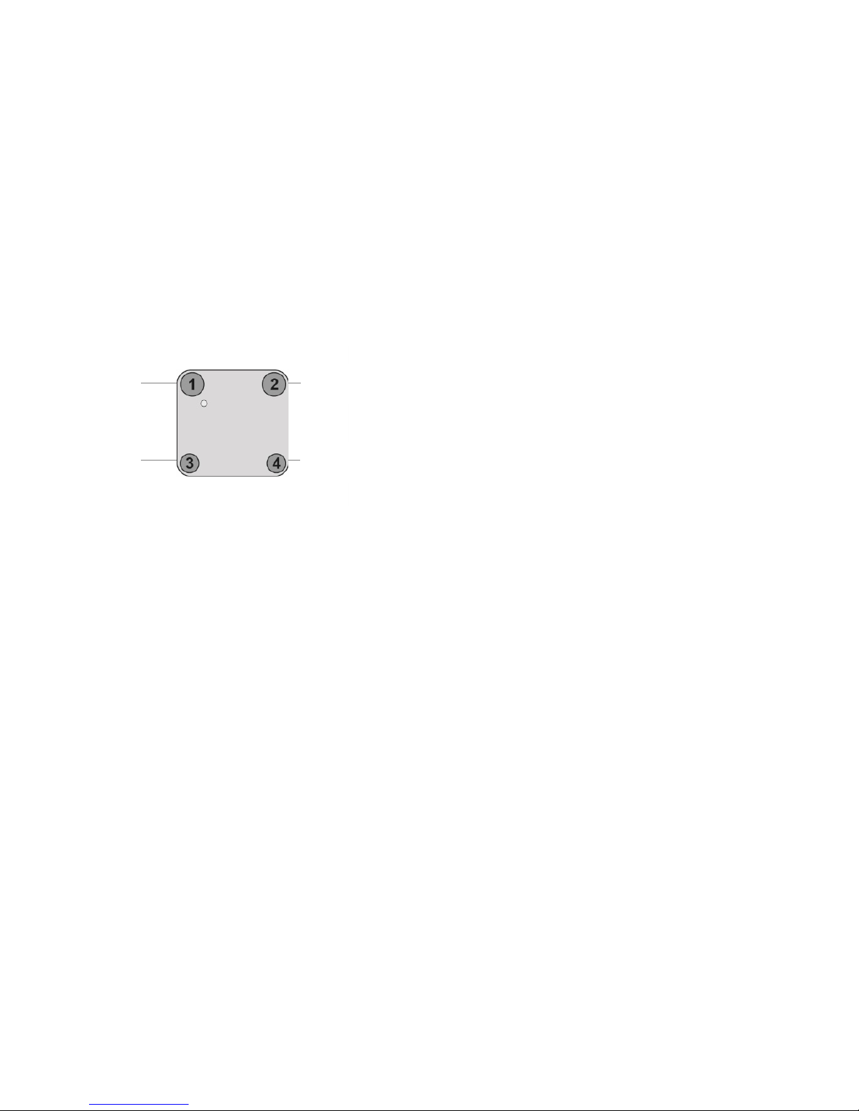
4 Groups are controlled with single button (parameter 1/2 = 0)
The four buttons 1-4 control one single control group each: 1→A, 2→B,
3→C, 4→D. Single click turns devices in the control group on, double
click turns them off. Click and hold can be used for dimming.
2 Groups are controlled with two buttons (parameter 1/2 = 1)
The buttons 1 and 3 control the control group A (button 1 turns on,
button 3 turns off), the buttons 2 and 4 control the control group B
(button 2 turns on, button 4 turns off). In case dimmers are controlled,
holding down the larger button will dim up, holding down the smaller
button will dim down the load. Releasing the button will stop the
dimming function.
4 Groups are controlled with two buttons and double click
(parameter 1/2 = 2)
This mode enhances the previous mode and allows to control two
further control groups C and D using double clicks. The devices
supports 8 different operating modes – this means the kind of
commands sent out when pushing a button. Operating modes either
directly control other devices or they issue various scene activation
commands to a central controller.
Operating modes for direct device control are:
• Direct control of associated devices with On/Off/Dim commands (parameter 11...14 = 1). Devices are
controlled using Basic Set On/Off commands and Switch-Multilevel Dim Start/Stop. This mode implements
communication pattern 7.
• Direct control of associated devices with only On/Off commands (parameter 11...14 = 2). Devices are
controlled using only Basic Set On/Off commands. On dimming Up event On is sent, on dimming Down Off is
sent. This mode also implements communication pattern 7.
• Switch-All commands (parameter 11...14 = 3). In this mode all neighboring devices will receive Switch-All set
On/Off command and interpret it according to their membership in Switch-All groups. This mode implements
communication pattern 7.
• Direct control of devices in proximity (parameter 11...14 = 6). Basic Set and Switch-Multilevel Dim commands
are sent to a device in proximity (50...100 cm) from the controller. Attention: In case there are more than one ZWave devices nearby all these devices may be switched. For this reason the proximity function should be handled
with care. This mode implements communication pattern 7.
• Door lock control (parameter 11...14 = 7). This mode allows direct control (open/close) of electronic door locks
using secure communication. The mode implements communication pattern 7.
Parameter 11-14 defin e what to send t o the groups
Grou p A Grou p C
Grou p B
Grou p D
Grou p A
ON
Grou p C
ON
Grou p B
ON
Grou p D
ON
Grou p A/C
ON
Grou p A/C
OFF
Grou p B/D
ON
Grou p
B/D
ON
Single clic ks operate A or B
Double clic ks operate C or D
Page 6

6
Operating modes for scene activation are:
• Direct activation of preconfigured scenes (parameter 11...14 = 5). Associated devices in an association group
are controlled by individual commands defined by Z-W ave command class „Scene Controller Configuration“. This
mode enhances mode direct control of associated devices with On/Off/Dim commands and implements
communication patterns 6 and 7. Please turn the button mode to „separate“ to allow different a scene ID on every
button.
• Scene activation in IP gateway (parameter 11...14 = 4). If configured correctly the buttons can trigger a scene in
a gateway. The scene number triggered is a combination of the group number and the action performed on the
button and has always two digits. The group number defines the upper digit of the scene number, the action the
lower digit.
• The following actions are possible:
1 On | 2 = Off | 3 = Dim Up Start | 4 = Dim Down Start | 5 = Dim Up Stop | 6 = Dim Down Stop
Example: Clicking/double clicking the button will issue scene triggers, scene 11 (button 1 click, event on), scene
12 (button double click 1, event off, single button control is used in this example)
• Activation of central scenes (parameter 11...14 = 8, default). Z-Wave Plus introduces a new process for scene
activation – the central scene control. Pushing a button and releasing a button send a certain command to the
central controller using the lifeline association group. This allows reacting both on button push and button release.
This mode implements communication patterns 6 but requires a central gateway supporting
Z-Wave Plus.
Child Protection
The device can be turned into a child protection mode. In this mode all local operation is disabled.
The child protection mode MUST be turned on wirelessly. However in protected by sequence mode it is possible to
unlock the device for local operation by pressing any button within 5 seconds. The unlock-state will last for 5 seconds.
Wake Up Intervals – How to communicate with the device
This device is battery operated and turned into deep sleep state most of the time to save battery life time.
Communication with the device is limited. In order to communicate with the device, a static controller C is needed in
the network. This controller will maintain a mailbox for the battery operated devices and store commands that can not
be received during deep sleep state. Without such a controller, communication may become impossible and/or the
battery life time is significantly decreased.
This device will wake up regularly and announce the wake up state by sending out a so-called Wake Up Notification.
The controller can then empty the mailbox. Therefore, the device needs to be configured with the desired wake up
interval and the node ID of the controller. If the device was included by a static controller this controller will usually
perform all necessary configurations. The wake up interval is a tradeoff between maximal battery life time and the
desired responses of the device.
The device will stay awake right after inclusion for 10 seconds allowing the controller to perform certain configuration. It
is possible to manually wake up the device by pushing button 2 in management mode. The minimum allowed wake up
time is 240s but it is strongly recommended to define a much longer interval since the only purpose of a wake up
should be the reporting of the battery status or an update of the child protection settings. The device has a periodic
wake up function however this function is disabled by the configuration parameter #25. This will protect the battery in
case the controller is accidently configuring a wake up interval. A wake up of the Wall Controller outside the range of
the controller will lead to lots of unsuccessful communication attempts draining the battery. Defining node ID of 0 as a
destination of the Wake Up Notification will disable the periodical wake up function as well.
It is possible to set the node ID to 255 to send Wake Up Notifications as broadcast. In this mode device takes more
time to go to sleep and drains battery faster, but can notify all its direct neighbors about a wake up.
Page 7

7
Node Information Frame
The Node Information Frame (NIF) is the business card of a Z-Wave device. It contains information about the device
type and the technical capabilities. The inclusion and exclusion of the device are confirmed by sending out a Node
Information Frame. Beside this it may be needed for certain network operations to send out a Node Information Frame.
Pressing button 2 in management mode will issue a Node Information Frame.
LED Control
1. Confirmation – Green, 1 second
2. Failure – Red, 1 second
3. Button press confirmation – Green, 1/4 second
4. Waiting for Network Management Mode selection – Slow green blinks
5. Waiting for group selection in Association Set Mode – Green fast blink
6. Waiting for primary controller function selection – Green fast blink
7. Waiting for NIF in Association Set Mode – Green-red-off blink
Associations
Z-Wave devices control other Z-Wave devices. The relationship between one device controlling another device is
called association. In order to control a different device, the controlling device needs to maintain a list of devices that
will receive controlling commands. These lists are called association groups and they are always related to certain
events (e.g. button pressed, sensor triggers, ...). In case the event happens all devices stored in the respective
association group will receive a common wireless command.
Association groups functions
1
Lifeline (max. nodes in group: 10)
2
Control Group A, controlled by button 1 or single clicks of buttons 1 and 3 (max. nodes in group: 10)
3
Control Group B, controlled by button 2 or single clicks of buttons 2 and 4 (max. nodes in group: 10)
4
Control Group C, controlled by button 3 or double clicks of buttons 1 and 3 (max. nodes in group: 10)
5
Control Group D, controlled by button 4 or double clicks of buttons 2 and 4 (max. nodes in group: 10)
Set and Unset Associations to Actuators
Associations can be assigned and remove either via Z-Wave commands or using the device itself. To control a Z-W ave
device from the Wall Controller the node ID of this device needs to be assigned to one of the four association groups.
This is a three-step process:
1. Turn the Wall Controller into management mode and hit button 4 within 10 sec. (LED is blinking green when
management mode is reached).
2. Within 10 sec. push the button you like the Z-Wave actuator to be assigned with. After 10 sec. the device goes
back to sleep. Single click means adding to this association group, double click means removing the node
selected in step (3) from this association group.
3. Find the Z-Wave actuator you like to control by the W all Controller. Hit the button on the device to issue a Node
Information Frame within 20 sec. A common way is hitting a control button one or three times. Please consult
the manual of the device to be controlled for more information how to issue an Node Information Frame. Any
button press on Wall Controller at this stage will terminate the process.
Special Functions as Z-Wave Controller
As long as this device is not included into a Z-Wave network of a different controller it is able to manage its own ZWave network as primary controller. As a primary controller the device can include and exclude other devices in its
own network, manage associations, and reorganize the network in case of problems.
Page 8

8
The following controller functions are supported:
Include (Add) other device in own network
Communication between two Z-Wave devices only works if both belong to the same wireless network. Joining a
network is called inclusion and is initiated by a controller. The controller needs to be turned into the inclusion mode.
Once in this inclusion mode the other device needs to confirm the inclusion – typically by pressing a button. For
Inclusion of Z-Wave devices into the own network the following two things have to be considered:
• In factory-default state only: Hit button 3 (secure) or button 4 (normal) to turn the controller into inclusion status.
Consult the manual of the new device how to start the inclusion process.
• Always: Turn into management mode by pressing all four buttons for 5 seconds. The green LED will start blinking
slowly. Now hit button 3 to activate the primary controller functions. The green LED will blink faster. Now hit button
1 (secure) or button 2 (normal) to turn the controller into inclusion state. Consult the manual of the new device how
to start the inclusion process.
If current primary controller in your network is in special SIS mode this and any other secondary controller can also
include and exclude devices. To become primary a controller have to be reset and then include a device.
Exclude (Remove) device from network
The primary controller can exclude (remove) devices from the Z-Wave network. During exclusion the relationship
between the device and the network of this controller is terminated. No communication between the device and other
devices still in the network can happen after a successful exclusion. The controller needs to be turned into the
exclusion mode. Once in this exclusion mode the other device needs to confirm the exclusion – typically by pressing a
button.
Attention: Removing a device from the network means that it is turned back into factory default status. This process
can also exclude devices from its previous network.
Turn into management mode by pressing all four buttons for 5 seconds. The green LED will start blinking slowly. Now
hit button 3 to activate the primary controller functions. The green LED will blink faster. Now hit button 3 again to turn
the controller into exclusion status. Consult the manual of the new device how to start the exclusion process.
Shift primary role to a different controller
The device can hand over its primary role to another controller and become secondary controller. Turn into
management mode by pressing all four buttons for 5 seconds. The green LED will start blinking slowly. Now hit button
3 to activate the primary controller functions. The green LED will blink faster. Now hit button 4 to turn the controller into
primary shift mode. Consult the manual of the new device how to start the primary shift process for the new primary
controller.
Configuration Parameters
Z-Wave products are supposed to work out of the box after inclusion, however certain configuration can adapt the
function better to user needs or unlock further enhanced features.
Button 1 and 3 pair mode (Number 1, Size 1)
In separate mode button 1 works with Group A, button 3 with Group C. Click is ON, Hold is dimming UP, Double click
is OFF, Click-Hold is dimming DOWN. In pair button 1/3 are UP/DOWN correspondingly. Click is ON/OFF, Hold is
dimming UP/DOWN. Single clicks works with Group A, double click with Group C.
Value
Description
0
Separately
1
In pair without double clicks (default)
2
In pair with double clicks
Page 9

9
Button 2 and 4 pair mode (Number 2, Size 1)
In separate mode button 2 works with control group B, button 4 with control group D. Click is ON, Hold is dimming UP,
Double click is OFF, Click-Hold is dimming DOWN. In pair button B/D are UP/DOWN correspondingly. Click is
ON/OFF, Hold is dimming UP/DOWN. Single clicks works with Group B, double click with Group D.
Value
Description
0
Separately
1
In pair without double clicks (default)
2
In pair with double clicks
Command to control Group A (Parameter 11, Size 1)
This parameter defines the command to be sent to devices of control group A when the related button is pressed.
Value
Description
0
Disable
1
Switch on/off and Dim (send Basic Set and Switch Multilevel)
2
Switch on/off only (send Basic Set)
3
Switch all
4
Send scenes
5
Send preconfigured scenes
6
Control devices in proximity
7
Control door lock
8
Central scene to gateway (default)
Command to control Group B (Parameter 12, Size 1)
This parameter defines the command to be sent to devices of control group b when the related button is pressed.
Value
Description
0
Disable
1
Switch on/off and Dim (send Basic Set and Switch Multilevel)
2
Switch on/off only (send Basic Set)
3
Switch all
4
Send scenes
5
Send preconfigured scenes
6
Control devices in proximity
7
Control door lock
8
Central scene to gateway (default)
Command to control Group C (Parameter 13, Size 1)
This parameter defines the command to be sent to devices of control group C when the related button is pressed.
Value
Description
0
Disable
1
Switch on/off and Dim (send Basic Set and Switch Multilevel)
2
Switch on/off only (send Basic Set)
3
Switch all
4
Send scenes
5
Send preconfigured scenes
6
Control devices in proximity
7
Control door lock
8
Central scene to gateway (default)
Page 10

10
Command to control Group D (Parameter 14, Size 1)
This parameter defines the command to be sent to devices of control group A when the related button is pressed.
Value
Description
0
Disable
1
Switch on/off and Dim (send Basic Set and Switch Multilevel)
2
Switch on/off only (send Basic Set)
3
Switch all
4
Send scenes
5
Send preconfigured scenes
6
Control devices in proximity
7
Control door lock
8
Central scene to gateway (default)
Send the following switch all commands (Number 21, Size 1)
Value
Description
1
Switch off only (default)
2
Switch on only
255
Switch all on and off
Invert buttons (Number 22, Size 1)
Value
Description
0
No (default)
1
Yes
Blocks wake up even when Wake Up Interval is set (Number 25, Size 1)
If the Wall Controller wakes up and there is no controller nearby, several unsuccessful communication attempts will
drain battery.
Value
Description
0
Wake up is blocked (default)
1
Wake up is possible if configured accordingly
Send unsolicited battery report on Wake Up (Number 30, Size 1)
If the Wall Controller wakes up and there is no controller nearby, several unsuccessful communication attempts will
drain battery.
Value
Description
0
No 1 To same node as Wake Up Notification (default)
2
Broadcast to neighbors
Command Classes
Supported command classes
ALL SWITCH BATTERY POWERLEVEL
Version 1
WAKE UP
Version 2
ASSOCIATION
Version 2
VERSION
Version 2
SCENE CONTROLLER CONFIGURATION
Version 1
MULTI CHANNEL ASSOCIATION
Version 2
Page 11

11
MULTI COMMAND ENCAPSULATED
Version 1
CONFIGURATION
Version 1
MANUFACTURER SPECIFIC
Version 1
CENTRAL SCENE
Version 1
SECURITY
Version 1
Z-WAVE PLUS INFORMATION
Version 1
DEVICE RESET LOCALLY
Version 1
ASSOCIATION GROUP INFORMATION
Version 1
BASIC
Version 1
SCENE ACTIVATION
Version 1
MULTILEVEL SW ITCH
Version 1
DOOR LOCK
Version 1
MULTI CHANNEL
Version 1
DOOR LOCK
Version 1
MULTI CHANNEL
Version 1
ALL SWITCH
Version 1
POWERLEVEL
Version 1
Controlled command classes
CENTRAL SCENE
Version 1
SECURITY
Version 1
BASIC
Version 1
SCENE ACTIVATION
Version 1
MULTILEVEL SW ITCH
Version 1
DOOR LOCK
Version 1
MULTI CHANNEL
Version 1
ALL SWITCH
Version 1
Technical Data
IP Rating
IP 20
Battery Type
1 * CR2032
Frequency
868.42 MHz
Wireless Range
Up to 100 m outside, on average up to 20 m inside buildings
Explorer Frame Support
No
Device Type
Portable Controller
Routing
No
FLiRS
No
Firmware Version
1.3
Battery Life
> 2 years
Explanation of Z-Wave specific Terms
• Controller is a Z-Wave device with capabilities to manage the network. Controllers are typically gateways, remote
controls or battery operated wall controllers.
• Slave is a Z-Wave device without capabilities to manage the network. Slaves can be sensors, actuators and even
remote controls.
• Primary Controller is the central organizer of the network. It must be a controller. There can be only one primary
controller in a Z-Wave network.
• Inclusion is the process of bringing new Z-Wave devices into a network.
• Exclusion is the process of removing Z-Wave devices from the network.
• Association is a control relationship between a controlling device and a controlled device.
• Wake up Notification is a special wireless message issued by a Z-Wave device to announce that is able to
communicate.
• Node Information Frame is a special wireless message issued by a Z-Wave device to announce its capabilities and
functions.
Page 12

12
Disposal Guidelines
The product contains batteries. Please remove the batteries when the device is not used.
Do not dispose of electrical appliances as unsorted municipal waste, use separate collection facilities. Contact your
local government for information regarding the collection systems available. If electrical appliances are disposed of in
landfills or dumps, hazardous substances can leak into the groundwater and get into the food chain, damaging health
and well-being.
Support
Should you encounter any problem, please give us an opportunity to address it before returning this product. Most
questions regarding Z-Wave wireless communication standard can be answered through the international community
at www.zwave.info.
If your question can‘t be answered there, please contact us by email: info@popp.eu
© 2015 POPP & Co.
While the information in this manual has been compiled with great care, it may not be deemed an assurance of product
characteristics. Popp & Co. shall be liable only to the degree specified in the terms of sale and delivery.
The reproduction and distribution of the documentation and software supplied with this product and the use of its
contents is subject to written authorization from Popp & Co. We reserve the right to make any alterations that arise as
the result of technical development.
Phone: +44 (0) 20 7419 5726
eMail: info@popp.eu
Web: www.popp.eu
 Loading...