

Page 1
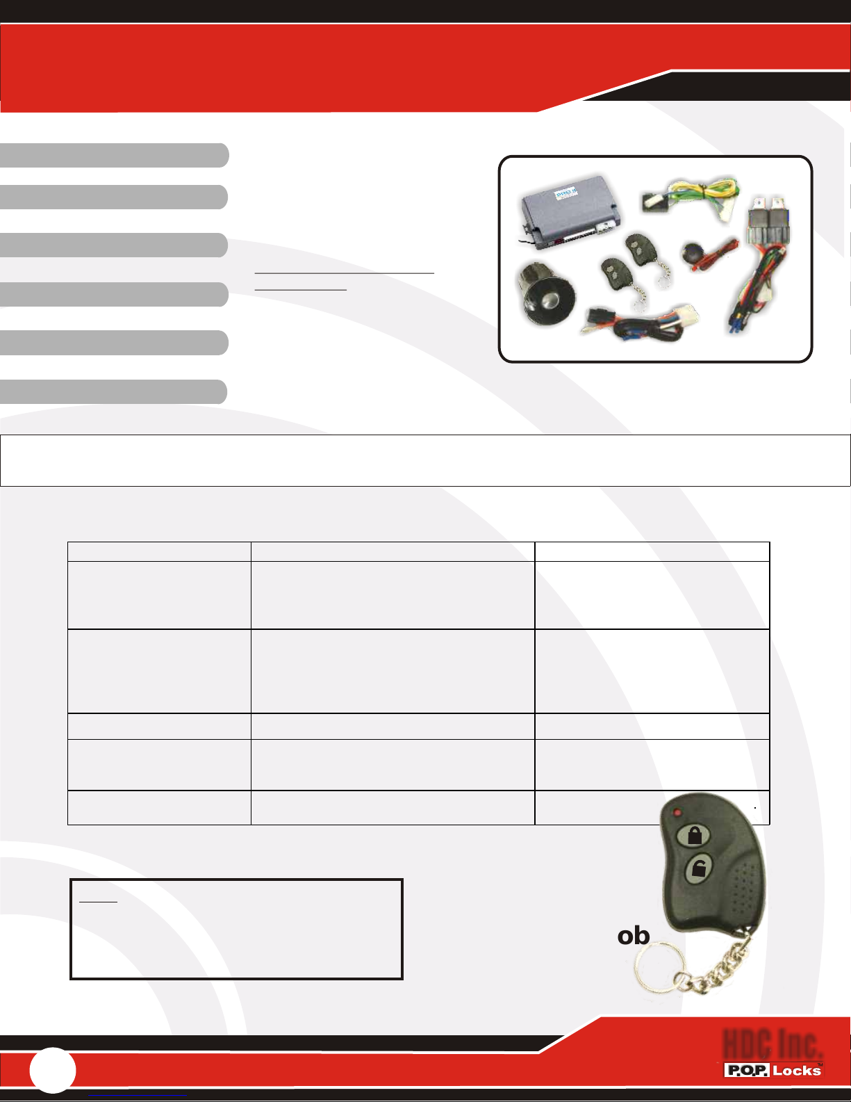
Pro Controller II
Programming Guide
Pat. Pend
SMART KEYLESSSMART KEYLESS
CODE LEARNINGCODE LEARNING
SEQUENTIAL LOCKINGSEQUENTIAL LOCKING
ZONE SECURITYZONE SECURITY
DOOR OPEN WARNINGDOOR OPEN WARNING
FOR MORE INFORMATION
AND PRODUCTS, VISIT:
www.poplocks.com/fleetwood03.html
Any questions please Email
[email protected]
All enquiries please reference
Product ID. M3
Pat. Pend
FLEX SWITCH CAPABLEFLEX SWITCH CAPABLE
USER MANUAL TO REMAIN IN VEHICLE
PLRB Pro Alarm Features Key Fob & RS /Switch Operations Pat. Pend.
Button Functions Conditions
a. Arms and locks all doors
1
2
1 and 2 Press & hold 2 sec. to activate panic Anytime
b. Vehicle locator with sound
c. Stops alarm temporarily
d. Locks doors in 1, 2, 3 order
a. Disarms
b. Unlocks doors in order, relay 1, 2, 3, if
3C On first push Relay 3 is activated,
pressed again rapidly activates Relay 1, 2
c. Stops alarm
Alarm is disarmed
Alarm is armed
Alarm is sounding
While driving
Alarm is armed
While driving
Alarm is sounding
RS-SWITCH
LOCK
RS-SWITCH
UNLOCK
Note: Please refer to the above table and follow operating instructions for all function.
Note: * Optional feature not essential for basic system operation
Note:
During any programing depress Valet firmly.
Rapid Valet inputs often are not detected.
Example: A Valet input of 10 press will need
min 5 seconds @ ½ second between pushes.
1
www.poplocks.com
a. RS switch locks and arms all doors,
activating (ZONE ALARMING)
b. Press & hold for 2 sec. to activate panic
a. RS Switch unlocks (3C ON or OFF) and
disarms.
Anytime
Anytime
T-25
Key Fob
HDC Inc.
Page 2

Pro Controller II
Pat. Pend
Programming Guide
Features:
Code Learning
a. Within 5 seconds after power ON and then ACC ON, press button 1 and 2 at the same
time, siren will sound 3 times to indicate entering code-learning mode.
b. Then within 5 seconds, press any button on the transmitter, and siren will chirp as
confirmation that transmitter has been recognized and be compatable with the system. The
chirp times will correspond to the transmitter learned. For example, the second transmitter
learned and siren will chirp twice. maximum 12 transmitters can be learned.
c. During code learning, if there is no action after 5 seconds, system will exit the mode.
Arming
a. Press button 1
b. Siren will sound once
c. Parking light will flash once
d. Doors will be locked at a 0.5 sec
e. The doors will be automatically sequentially locked (in relay order 1,2,3).
f. LED will flash slowly
g. Disable engine starter (if starter kill relay is connected). After 5 seconds, alarm is armed.
Sensor triggered within this period will be bypassed. Please refer to SENSOR BY
PASSED WARNING for details.
h. Pressing RS switch LOCK button will enter arming but disable the shock sensor and
ultra-sonic sensor
Disarming
a. Press button 2 or press RS switch UNLOCK button
b. Siren will sound 3 times and parking light will flash 3 times. If siren sounds 4 times and
lights flash 4 times, it means the alarm has been triggered. If chirp deleted selected, only
parking lights will flash and no siren sounds.
c. Doors will unlock at 0.5 sec.
d. Doors will be automatically sequentially unlocked if “3C OFF” is selected. The order will
be relay 1, relay 2, then relay 3. If “3C ON” is selected, press button 2 once and it will output
only relay 3, the external relay. Press button 2 again within 3 sec, will unlock relay 1, then
relay 2. The step signal will follow after unlock output finished.
e. Enables engine (if starter kill relay connected)
f. Dome light will be turned on for 30 sec. or light off when ACC ON
g. If alarm is in passive arming mode, LED will flash quickly. After 30 seconds alarm will
be automatically re-armed.
Anti-carjacking
a. When key is in and ACC is in the ON position and the doors are closed, press the button 2
once and door opened within 8 sec. anti car-jacking mode is activated.
b. When the door is closed, a 30 sec. countdown starts and LED blinks rapidly.
c. After 30 seconds, siren will chirp once every 2 sec. After 20 seconds sound is continuously.
Also, parking lights will continuously flash. Siren will stop sounding & parking lights will
stop flashing when ACC is turned to OFF. After ACC OFF, engin disabled to be
re-started (if kill starter relay connected).
d. To exit the anti car-jacking: Press button 3 for over 2 sec. in ACC ON mode.
2
www.poplocks.com
HDC Inc.
Page 3

Pro Controller II
Pat. Pend
Programming Guide
Emergency disarming-override
ACC OFF the ON for 5 times, and stop at the last ON for 10 sec, LED steady ON, and
system will disarm or exit anti car-jacking
“Smart Unlocking” Automatic Door Unlock (3C OFF)
When ACC OFF, the doors will be automatically unlocked in relay 1, 2, and 3 order. In “3C
ON” mode, only the external unlock relay 3 will be activated. Relay 1 and 2 would need to be
functioned by pressing button 2 rapidly twice
“Smart Locking” Automatic door lock
When ACC ON, after 16 seconds all doors will be automatically locked in order (lock relay
1, relay 2, then relay 3
Valet Mode
a. ACC OFF then ON for 3 times, and stop at the last ON for 10 sec, then LED steady ON,
and system will enter into Valet Mode
b. Follow above procedure to exit Valet Mode
Hand Free Function (For T54 Transmitter only)
a. To open the hand free function, press and hold the button 4, till LED is off. (To close hand
free function, please press and hold button 4 till LED is off)
b. In arming mode and ACC OFF, if car alarm can’t receive the signal from T4 transmitter,
the system will enter auto rearming mode, 30 sec later, it will enter arming mode and
door lock
Panic
a. Press button 1+2 or press lock button on RS, the siren will sound and parking lights will
flash for 30 seconds.
b. Pressing button 1 or 2 will stop panic
Vehicle finder
a. Alarm is armed
b. Press button 1: Siren will sound once and parking lights will flash 10 times.
c. Press button 2 to stop it.
Shock Sensor
a. If vehicle is lightly touched once, siren will sound for 1 second. If vehicle is touched
again within 8 seconds, siren will sound and parking lights flash for 30 seconds
b. If vehcile receives a heavy shock, siren will sound for 30 seconds and parking lights will
flash for 30 seconds.
Sensor triggered in arming
a. Shock sensor: see above explanation
b. If an additional sensor triggered, siren will sound for 30 seconds and parking lights will
flash for 30 seconds.
c. If door triggered, siren will sound for 30 seconds and parking lights will flash for 30
seconds for 3 cycles
d. If ACC is triggered, siren will sound and parking lights will flash
3
www.poplocks.com
HDC Inc.
Page 4
Pro Controller II
Pat. Pend
Programming Guide
Door lock control
a. Driving: press button 1 or lock button on RS to unlock doors. The doors can be locked after 0.5 sec.
b. Press button 2 or unlock button on RS to unlock doors. The doors can be unlocked after 0.5 sec.
c. Press door switch lock once to lock all doors sequentially
d. Press door switch unlock once to unlock all doors sequentially (when 3C OFF) or press twice
to unlock all doors (when 3C ON)
Auto rearming
When alarm is disarmed, if ACC is not ON and doors not open, after 30 sec system will be
automatically rearmed.
Door open warning
If one of the doors is opened when the ignition is ON, the parking lights will flash 1 min max
for warning coming vehicles.
Memory function
The alarm memory will record the last condition when the power is cut off
Sensor bypass warning
Pressing button 1 during the first 5 seconds, if any sensor is triggered, that sensor will
be by-passed, and siren will chirp twice as indicated. The by-passed sensor will be
back and functioning after 2 seconds of no trigger activity
Function Selection
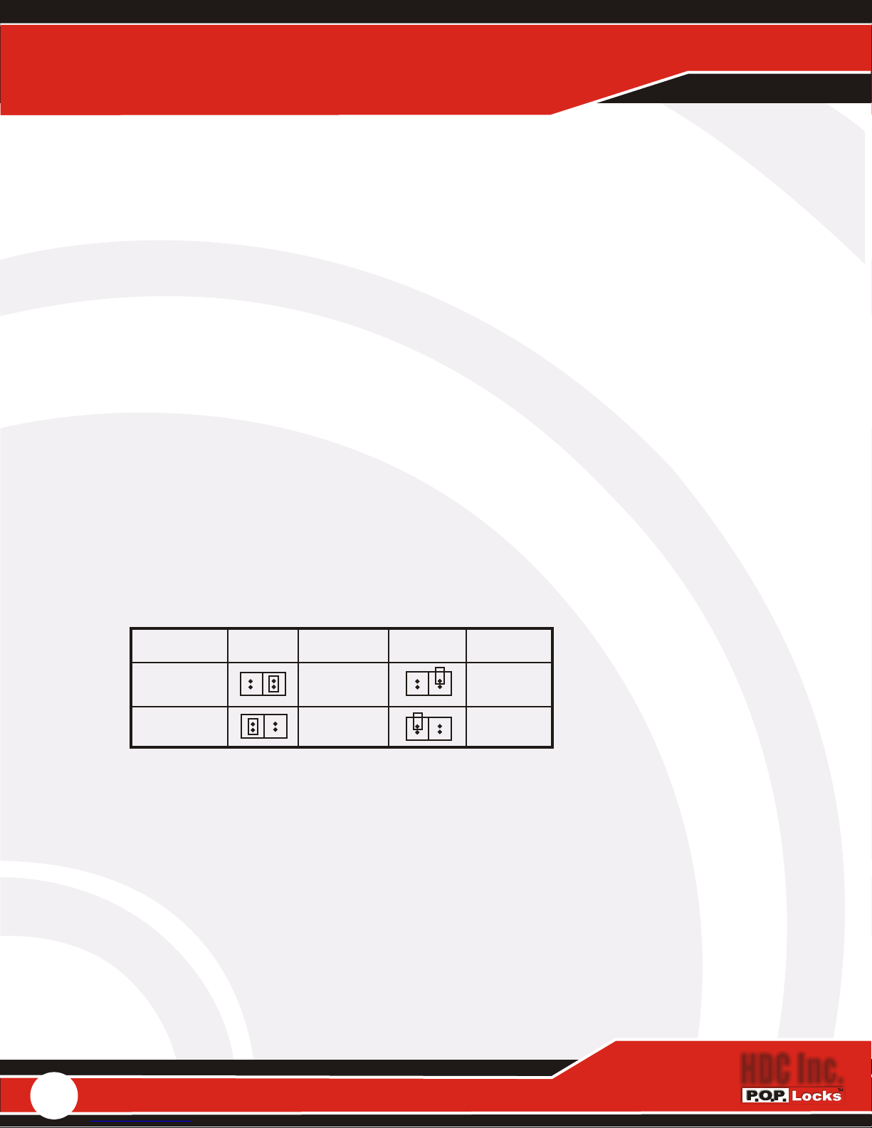
There are two jumper selections (J1 and J2). See the table as below.
Important: All jumper selections have to be determined before install. Otherwise, you have to
power off the module again for reset.
JUMPER MODE FUNCTION MODE FUNCTION
J1: 3C ON/OFF ON OFF
J2: Anti-carjacking OFF OFF
LED condition
a. When armed, LED flash slowly once a sec.
b. When armed, if alarm is triggered, LED will flash quickly
c. LED will flash quickly when system starts Passive Arming count down
d. Valet mode: LED constantly ON.
4
www.poplocks.com
HDC Inc.
Page 5
Pro Controller II
Programming Guide
Pat. Pend
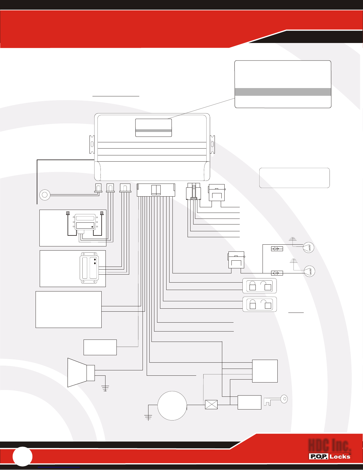
Please Note: Pro Controllers are installed often with a
reduced feature harness. To add other accessories it will
be necessary to add a full feature harness Part # 14PH.
Visit our web site:.poplocks.com regarding this or other
accessories or how to manuals.
Antenna
LED & Valet
Ultrasonic
Sensor
See Detail
US-1
*
Zone 2
Shock
Sensor
See Detail
SS-1
*
Zone 2
Third (3C)
Channel
Relay
See Detail
910-1
*
Siren
C3 Unlock
Green/White
C3 Lock
Blue/White
Dome Pos.+
Output
Pink
Dome
White
Wiring Show Is
Not Necessary In
*
*
*
Pat. Pend.
ID. M3FL
PRO II
CONTROLLER
poplocks.com
Order.
Black/White
Neg.- On Unlocked
Door/ Step Output
Green Pos.+
Brown Neg. - Unlock
Purple Neg. - Lock
Purple / White Pos.+ Unlock
*
Brown / White Pos.+ lock
*
Gray Neg.- Trigger Input
*
Blue Pos.+ Trigger Input
*
Yellow
IGN On
Orange
*
*
*
30 A
Red Pos. +
Green Unlock C2
Brown Unlock C1
White Lock C1
Blue lock C2
Black Ground -
10 A
*
*
Zone 1
ID. M3FL
Pat. Pend.
PRO II
CONTROLLER
poplocks.com
Part # PLRB-Pro
12 Volt DC
Zone Alarm
Sequential Locking
Code Learning
Flex Switch Compatible
Pat. Pend.
Not Essential For
Basic Operation
*
Main Power Input
Grounding
Sequential Locking
Outpots
}
Neg.-
Running
Lamps
Zone 1
Relay
85
86
87
30
Neg.-
Momentary
Switches
Neutral @ Rest
Note:
Activation Of Hard-wire
Switches WILL NOT
Activate Any Security
Features.
RS-1 Flex Switch Activates
Zone 2 Only
Fob Activates Zone 1&2
a
Neg.-
5
www.poplocks.com
Neg.-
Starter
Solenoid
Cut
Start
Ignition
Switch
HDC Inc.
Page 6
T-25 Fob & Flex Switch I & II
Optional
Pat. Pend
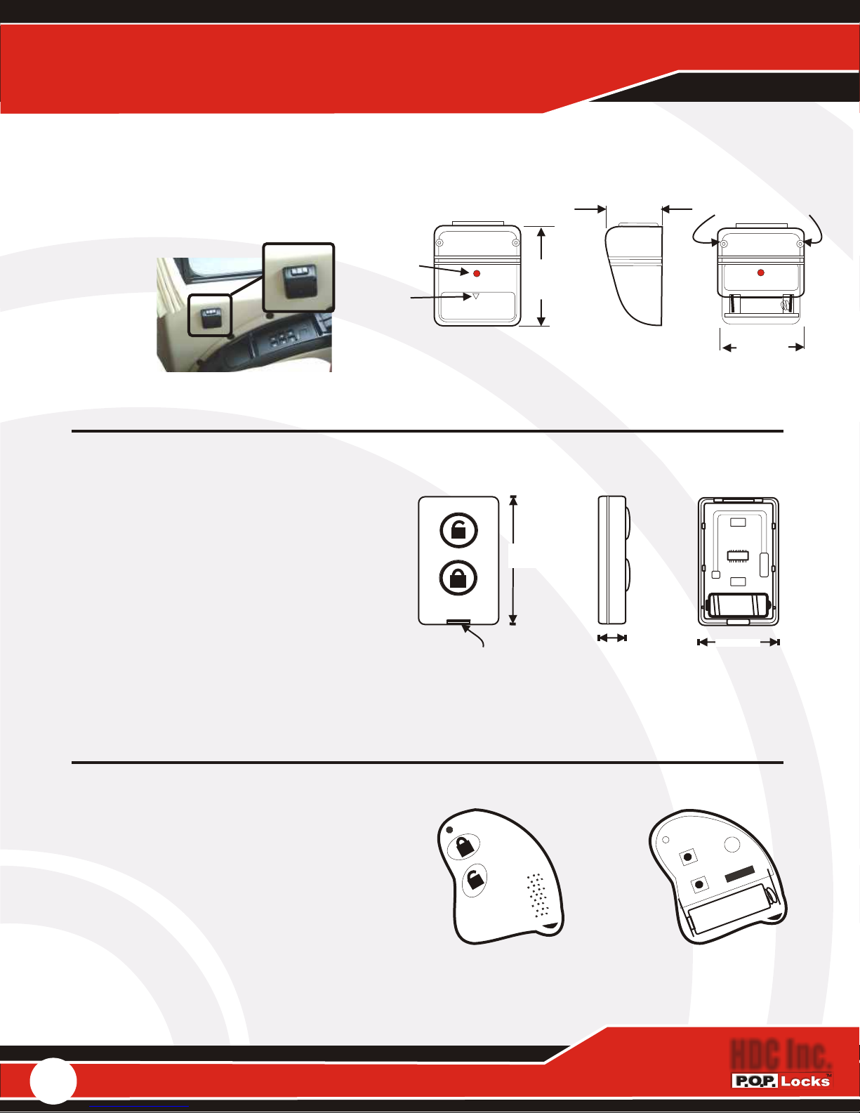
Flex Switch I (RSI)
Mounting Flex Switch (RS1) is done using
the 2 Fasteners through mounting holes.
Carefully select
the area best
suited for its
placement.
Confirmation
Led
Finger Pull
Front
With Battery
Cover
63.35mm
2.500in.
HDC.Inc.
Fig. A
Designed with through holes for
mounting on any flat surface.
31.65mm
1.250in.
Side View
2-4 X Min. 5/8 Long
Wood / Metal Screw
- +
56.98mm
2.250in.
Fig. B
Flex Switch
is coded using the same process as Key Fobs described in User Manual code learning section.
Flex Switch II (RS2)
Replacing the Flex Switch II battery the
cover must be removed. Using only a
fingernail or paper clip, depress the tab on
the bottom of the flex switch. Cover will
hinge at the top revealing the inside
components. Replacement batteries are 12v
part # GP23A, CN23A, El12 and Vr22 or
similar class battery.
Replacement battery must be installed as
shown in Fig B. Its orientation is specific to
+- polarities clearly marked.
Replace cover and test.
Front and Cover
Depress to open
Fig. A
The battery mates to the contacts and cradles
inside the bezel. Battery held in place only by
2 1/3 inches
59.182 mm
cover and contacts.
Side
.5 inches
12.7 mm
Front Cover Off
+
1.5 inches
38.1 mm
Fig. B
+
-
-
T-25 Transmitter
To replace the T-25 Key Fob battery (Fig D.),
the shell of the transmitter must be removed.
Pry between the depression around
the shell and separate the fob into 2 pieces
exposing the battery as shown in Fig. D.
Replacement batteries are 12v part # GP23A,
CN23A, EL12 and VR22 or similar class battery.
Replacement battery must be installed as shown
in Fig. D. Its orientation is specific to - + polarities
clearly marked. Replace cover and test.
6
www.poplocks.com
Fig. C
-
-
TTE
TTE
-
R
R
+
+
+
A Y
A Y
B
B
Fig. D
Front With Cover Off
HDC Inc.
Page 7
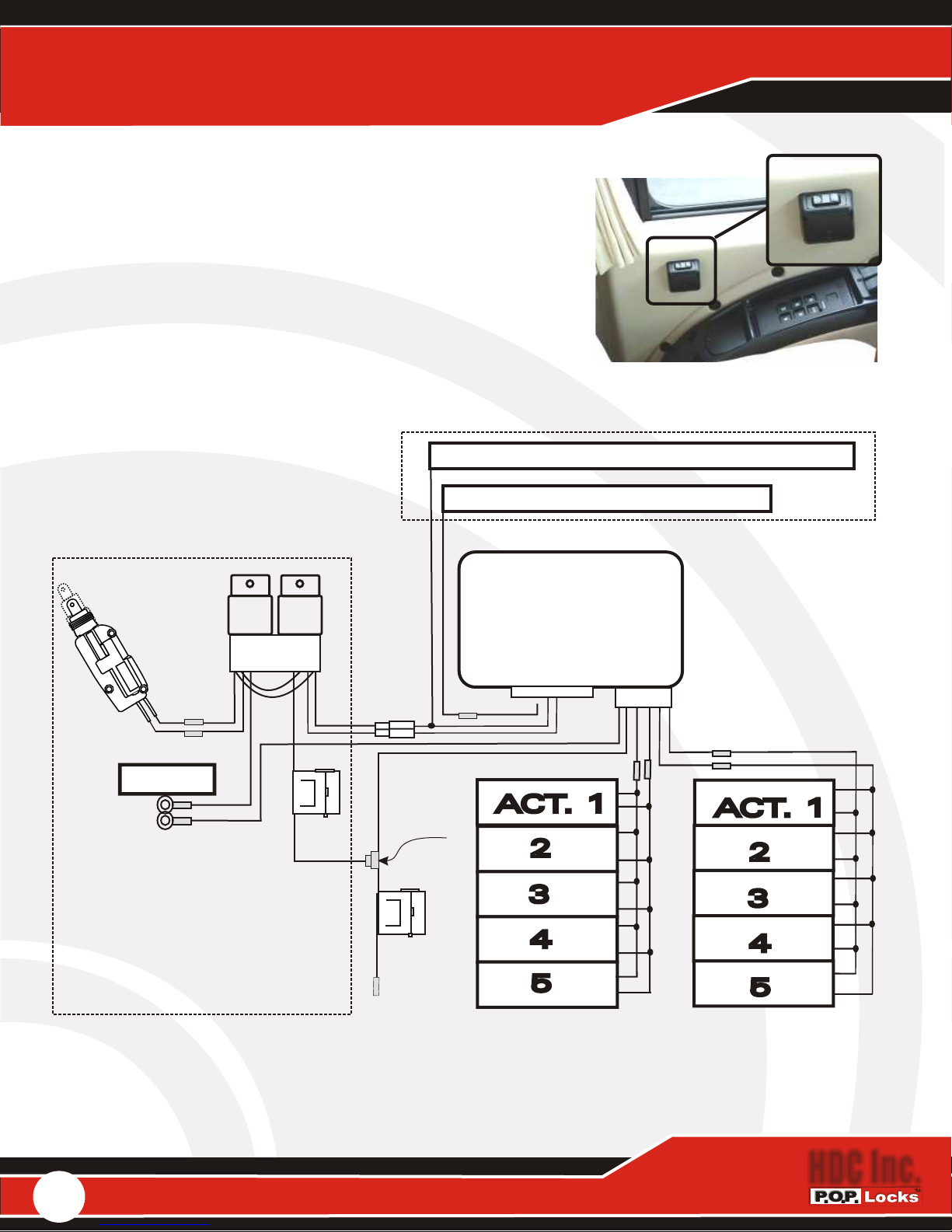
Optional Alternate Trigger
PLRB-Pro Controller, PL910-1 3C & Alternate Trigger
Flex Switch is coded using the same process
as Key Fobs described in User Manual code
learning section.
Mounting Flex Switch (RS1) is done using the 2 Fasteners
through mounting holes. Carefully select the area best
suited for its' placement.
Separating Third ( 3C ) By Alternate Trigger
Unlock Neg-, Green/White To Output 3C.
Lock Neg- Purple Lock Input.
(3C On) Third Channel
Output First To Unlock
11
Pat. Pend.
30 AMP
30 AMP
12 VOLT
12 VOLT
A
A
en
en
S
S
t d
t d
s
s
U
U
n
n
k
k
.
.
TM
TM
te P
te P
a
a
Lo
Lo
P
P
P
P
C c
C c
&
&
O c
O c
D
D
P
P
d
d
H In
H In
e
e
t
t
en
en
Pat
Pat
30 AMP
30 AMP
12 VOLT
12 VOLT
PlugPlug
30 A
30 A
Ground
12VDC
12VDC
Max.
Outboard Relay
Max.
Part # PL910p.
5 Additional
Compartments Or
Independent 3rd
Channel Output.
Detail PL910-1
Plug
Provided
Tee Tap
30 A
30 A
12VDC
12VDC
Max.
Max.
22
PRO Controller
Output
Schematic
14 pin
ACT.
6 Pin
1
2
3
4
5
Second To Lock
Left Baggage &
Compartment
ACT.
1
2
3
4
5
Third To Lock
Right Baggage &
33
Compartment
6
www.poplocks.com
HDC Inc.
 Loading...