

Page 1
Installation Instructions
Tailgate Lock
PL8661
Honda Ridgeline
2005 and Up
With or Without
Backup Camera
Package Contents:
Lock Bezel, 2 Keys, Mounting Bracket
Locking Bolt Linkage, Crank Linkage
2 Screws #8-32 x 1 1/2”, 1 Bolt 1/4” x 2”
Locking Bolt Linkage and Slide Bolt
Long and Short Wire Harness, Zip Ties
Manual Lock Install
Tools Required:
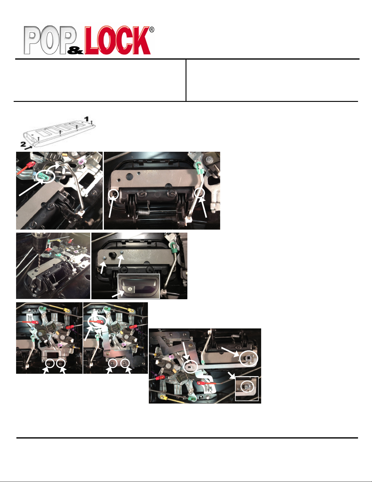
STEP 1 - Lower the tailgate. Remove the four Phillips head screws from the top trim, slide the trim
to the right (passenger) side using a rubber mallet and lift to remove it. Apply downward pressure
on the top trim if it bows up. Remove the white clips that remain on the tailgate by turning them 45
degrees to pull out. NOTE THE ORIENTATION BEFORE REMOVEL. Remove the T40 torx
screws holding the interior trim panel and lift it off.
STEP 3 - Using the bracket holes as a template drill the two 3/16”
(or 5mm) holes and one 1/2” (or 12mm) hole. Insert the lock
assembly from the front of the bezel inserting the shaft through the
1/2” hole and aligning the two mounting holes on the bezel with the
mounting bracket. Insert the 2 supplied 8–32 x 1 1/2” screws through
the mounting bracket in to the bezel. Tighten the screws. DO NOT
OVER TIGHTEN. IF LOCK ASSEMBLEY BINDS LOOSEN
SCREWS UNTIL THE KEY MOVES FREELY!
10mm Socket, T40 Torx Bit, Phillip Head
5/32” Allen Wrench
Rubber Mallet
Power Drill
3/16” (or 5mm), 1/2” (or 12mm) Drill Bits
STEP 2 - Remove the handle rod from mechanicals by
turning the green rod clip and pulling the rod out of the
clip. Swing the rod up and out of the way. Remove the
two screws holding the factory handle in place; there are
tabs that will hold the handle from falling out of the
tailgate, but for extra assurance hold the handle in place
so not let the handle to fall. Install the mounting bracket
over the back side of handle and reinstall the two screws
and tighten. Reinstall the handle rod. The handle
should now look like picture.
STEP 6 - Check the functioning of the lock.
Lock-Turn the key to the right (passenger side)
to the two o’clock position and then then back
to 12 o’clock to lock.
STEP 4 - Remove the two mechanical assemble screws. Mount the Pop N Lock
bolt linkage under the upper latch rod as shown using the existing two mechanical
assemble screws. The lock assembly should look like picture.
STEP 5 - Install the crank rod
assembly by hooking the slotted
end onto the bolt linkage and the
square hole to the end of the lock
assembly shaft. Insert the
1/4” x 20 x 2” screw into the shaft
and tighten.
Unlock-Turning the key to the left (driver side)
to the ten o’clock position and then then back to
12 o’clock to unlock.
Technical Support:
Call 1-800-342-5911
Page 2
Power Lock Install
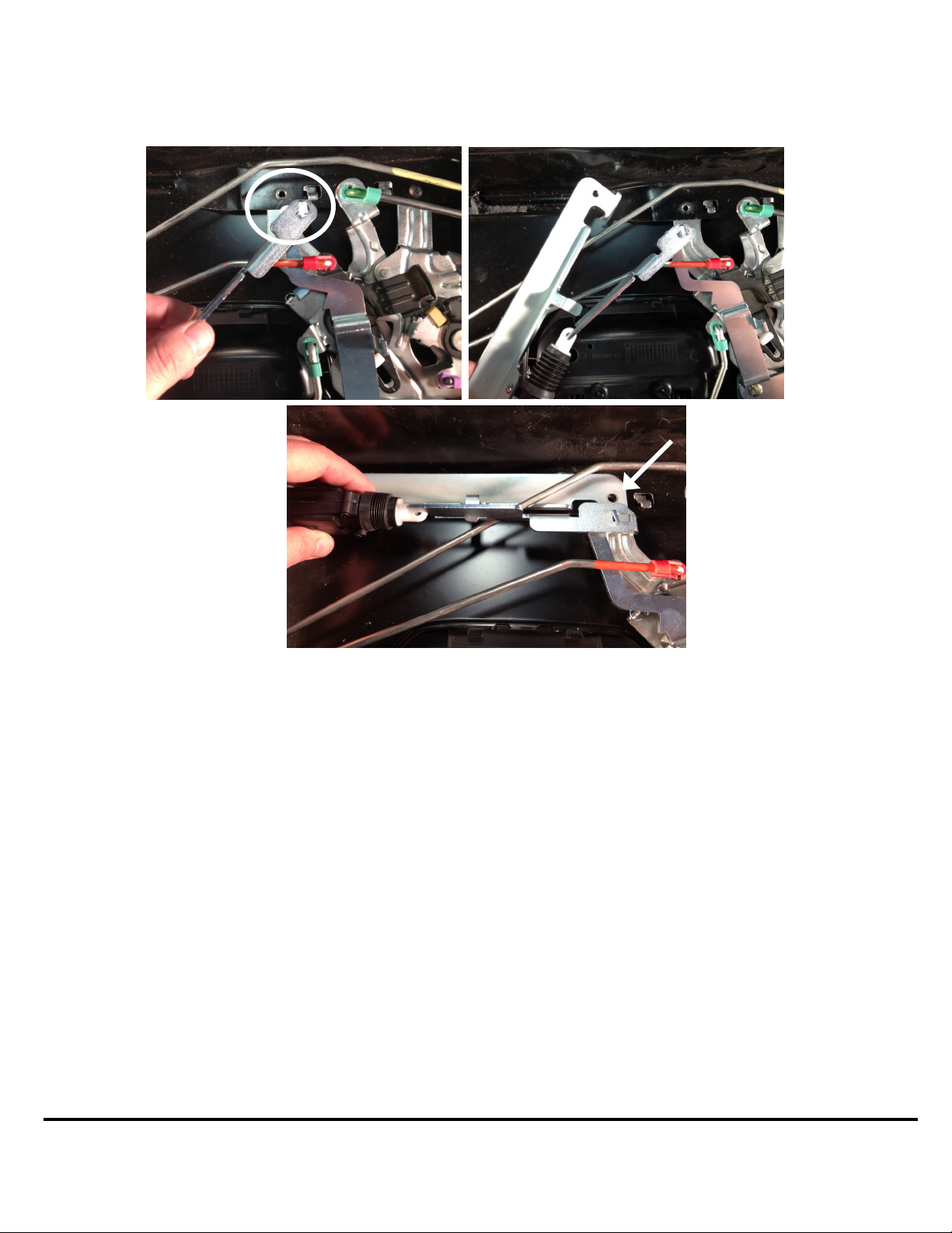
STEP 7 - Remove the driver side lower mechanical assembly screw. Hook the end of the slide bolt onto the t-post of the lock
bolt linkage and turn to position shown in the picture to the upper left. Hook the white plastic hook of the actuator onto t he slide
bolt and rock the actuator into place making sure the bolt end goes under and the slide bolt goes above the latch rod as shown in
the picture to the upper right and lower center. Reinstall the driver side lower mechanical assembly screw and tighten. Gently
slide the slide bolt to the lock and unlock position to verify function of lock.
STEP 8 - Wiring (there are other ways to run the wiring this is one way) - Snake the short wiring cable up the tailgate
through the driver side drain hole and connect it to the bullet connectors of the power unit. Secure with cable ties to prev ent the
wire from getting pinched or in the way of the latch rods. Connect the other end to the long wiring cable. Locate this connec tor
under the truck so that it is accessible for tailgate removal. Run the long wiring cable along the factory wire harness to th e engine compartment securing it with cable ties. Snake it into the driver’s compartment using the rubber grommet in the firewall
that the factory wire harness run through from the fuse box. Remove the driver side kick panel and run the wire down into the
driver side kick panel. The lock and unlock wires are located in the fuse box under the kick panel. The yellow with a black
stripe (lock) and the yellow with a green stripe (unlock) wires are in the small green plug that is located at the bottom front side
of the fuse box. Use the two blue wire taps to connect to theses two wires. Connect the male terminal ends of the long wire
harness to the blue tap connectors. Test the operation of the lock (if the tailgate lock works in the opposite direction as the door
locks un connect the male terminal and switch the wires that they were plugged into). Secure all the wiring and replace the kick
panel.
STEP 9 - Replace the interior trim panel of the tailgate using the torx screws removed in Step 1. Replace the white top trim
clips onto the tailgate, making sure they are oriented as noted in Step 1. Carefully locate the top trim over the clips and press it
firmly into place. You will hear and feel them snap into place. Adjust the position of the top rim once again using a rubbe r mallet. Reinstall the four Phillips Head screws.
Technical Support:
Call 1-800-342-5911
Page 3
 Loading...