


Renegade 26cc Line Trimmer
Model Numbers: 101PLT25FC
101PLT25FCB
Operator’s Manual
WARNING
To reduce the risk of injury, the user must read and understand the Operator’s
Manual. Save this manual.


Before you use your new Line Trimmer read this manual carefully to learn how to
operate and maintain your product correctly. Reading this manual will help you and
others avoid personal injury and damage to the product. Although Pope designs
safe state-of-the-art products, you are responsible for using the product properly and
safely. You are also responsible for training persons you allow to use the product
about safe operation.
READ THIS INFORMATION
Introduction
Thank you for purchasing a Pope® product.
We would like you to be completely satisfi ed with your new product, so feel free to contact an authorised
service dealer for help with service, genuine Pope parts or other information you may require. Or phone
the Pope Customer Service Centre for details of your nearest dealer on 1300 134 880.
The Pope warning system in this manual identifi es potential hazards and special safety messages that help
you and others avoid personal injury, even death. DANGER, WARNING and CAUTION are signal words
that identify the level of hazard. However, regardless of the hazard, be extremely careful. Two other words
“Important” and “Note” highlight other valuable information.
Signal Word Explanation
DANGER Indicates an imminently hazardous situation which, if not avoided, will result in death
or serious injury.
WARNING Indicates a potentially hazardous situation which, if not avoided, could result in death
or serious injury.
CAUTION Indicates a potentially hazardous situation which, if not avoided, could result in death
or serious injury.
Important Advises you of important information or instructions vital to the operation or
maintenance of the equipment.
Note Advises you of additional information concerning the operation or maintenance
of the equipment.
STOP

Contents
Safety Rules ................................................................................................................. 4
Symbols ........................................................................................................................ 5
Specifi cations .............................................................................................................. 6
Applications ................................................................................................................. 7
Features ......................................................................................................................... 7
Unpacking .................................................................................................................... 8
Assembly ...................................................................................................................... 9
Attaching the Upper Shaft with Engine to the Lower Bent Shaft Cutting Head 9
Attaching the Front Handle 9
Attaching the Grass Defl ector Shield 10
Fitting the Carry Strap 10
Operations .................................................................................................................... 11
Before you Start the Trimmer 11
Mixing the Fuel 11
Filling the Tank 11
Starting the Engine 12
To Start a Cold Engine 12
To Start a Warm Engine 12
Starting a Flooded Engine 12
Operating the Engine 13
To Advance the Cutting Line 14
To Advance the Cutting Line Manually 14
Grass Defl ector Line Trimming Cut-Off Blade 14
Maintenance ................................................................................................................. 14
Emissions Maintenance Schedule 14
Cleaning the Product 14
Replacing and Cleaning the Air Filter 15
Spark Plug 15
Replacing the Cutting Line 15
To Store the Product Long Term 16
Troubleshooting ........................................................................................................... 17
Warranty ....................................................................................................................... 18

Safety Rules
Physical Conditions of the Operator.• Do not
operate this product when tired, ill or under the
infl uence of alcohol, drugs or medication.
Clothing Requirements.• Always wear long
heavy pants, boots and gloves. Do not wear
loose clothing, jewellery , short pants, sandal or go
barefoot. Secure hair so that it is above shoulder
level to avoid entanglement in moving parts.
Protective Accessories Requirements.• Wear
safety eye protection when operating this product.
Wear hearing protection during extended periods
of operation.
C• ondition of Product before Use. Inspect the
product before each use. Replace damaged parts.
Check for fuel leaks. Make sure all fasteners are
in place and secure. Replace cutting attachment
parts that are cracked, chipped or damaged in
any way. Make sure the cutting attachment is
properly installed and securely fastened. Be
sure the cutting attachment guard is properly
installed and in the position recommended by the
manufacturer. Use only fl exible, non-metallic line
recommended by the manufacturer. For example,
never use wire or wire rope, which can break off
and become a dangerous projectile.
Proper Stance• . Keep fi rm footings and balance.
Do not overreach. Keep the cutting attachment
below waist level. Keep all parts of your body
away from the rotating cutting attachment and hot
surfaces.
Exhaust Gases• . Never start or run the product
inside a closed room or building; breathing
exhaust fumes can cause illness or death.
Fuelling.• Mix and pour fuel outdoors where there
are no sparks or fl ames. Slowly remove the fuel
cap only after stopping the engine. Do not smoke
while fuelling or mixing fuel. Wipe spilled fuel from
the product. Move at least 9m from the fuelling
source and site before starting the engine.
Work Area.• Clear the area to be cut before each
use. Remove all objects such as rocks, broken
glass, nails, wire or string that can be thrown
or become entangled in the cutting attachment.
Clear the area of bystanders, pets and children.
At a minimum, keep all bystanders, pets and
children outside a 15m radius. Because there still
may be a risk to bystanders from thrown objects,
bystanders should be encouraged to wear eye
protection. If you are approached while operating
the product, stop the engine or for those products
equipped with a clutch be sure the cutting
attachment has stopped moving.
Dangerous Environments.• To avoid falling, do
not use the product in damp or wet locations.
Controlling the Product.• During carburettor
adjustments the cutting attachment may spin.
Therefore you should wear protective equipment
and observe all safety instructions when adjusting
the carburettor. Be sure the cutting head has
stopped rotating before setting down or adjusting
the product. Maintain proper control until the
cutting head has completed stopped rotating.
Use the Right Product. • Use the product for the
intended purposes only.
Read and understand all instructions. Failure to follow all instructions may result in serious personal injury
as well as damage to product.
WARNING
4

Symbols
The following symbols are located on the product. Please study them and learn their meaning. Proper interpretation
of these symbols allows you operate the product better and safer.
Symbol Name Explanation
Safety Alert Indicates danger, warning or caution. Attention is required
in order to avoid serious personal injury. May be used in
conjunction with other symbols or pictographs.
Thrown Objects Thrown objects can cause severe injury. Wear protective
clothing and boots.
Keep Bystanders Away Keep all bystanders, especially children and pets, at least 15
metres from the operating area.
No Blade Do not install any type of blade on Model No. 101PLT25FC.
Use only fl exible, non-metallic line recommended by the
manufacturer.
Read Operator’s
Manual
Read the Operator’s Manual before starting or operating
this product. Failure to follow operating instructions and
safety precautions in the Operator’s Manual can result in
serious injury.
Eye and Ear Protection Thrown objects can cause severe eye injury. Wear eye
protection when operating this product. Wear hearing
protection during extended periods of operation.
Petrol and Oil Use unleaded petrol intended for motor vehicle use with an
Octane rating of 87 ([R + M] / 2) or higher. This product is
powered by a 2 cycle engine and requires pre-mixing and 2
cycle oil.
5
Specifi cations
Model Numbers: 101PLT25FC Engine: 26cc Full Crank
101PLT25FCB
Cutting Diameter: 400 mm
Line Size: 2.00 mm
Weight (Dry): 5.1 kg
Fuel Tank Capacity: 0.5 Litres
Fuel Petrol/Oil Mix: 25:1
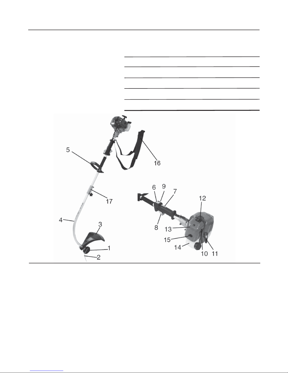
1. Line Trimmer Cutting Head
2. Cutting Line
3. Grass Defl ector Shield
4. Lower Bent Shaft
5. Front Handle
6. Engine On/Off Switch
7. Throttle Lever Release
8. Throttle Lever
9. Throttle Lock
10. Choke Lever
11. Starter Cord
12. Spark Plug Boot
13. Air Filter Housing Cover
14. Fuel Tank
15. Primer Bulb
16. Carry Strap
17. Shaft Connection Piece
6

Applications
Use this product for the following applications:
Cutting grass, weeds and light undergrowth•
Edging along sideways and driveways•
Do not attempt to use this product as a drive unit for other work tools or tool kits of any kind.•
Features
Exercise caution when using the product. Careless actions, for even a fraction of a second, can result in
serious personal injury.
Your new product is equipped with the following features:
Engine
The engine is powerful and easy to start. It is effectively counterbalanced, with a full crank which provides less
vibration and more durability.
Dual Line
The dual line permits more effi cient cutting than a single line.
Grass Defl ector
The grass defl ector helps protect you from fl ying debris. The defl ector also includes a cutting blade that
automatically trims the line to the correct length.
Ergonomic Handle Design
The design of the product provides for easy handling. It is designed for comfort and ease of grasp when
operating in different positions and at different angles.
WARNING:
Do not attempt to modify this product or create accessories not recommended for use with this product.
Any such alteration or modifi cation is misuse and could result in a hazardous condition leading to serious
personal injury and will void your guarantee.
WARNING:
7

Unpacking
Instructions
Carefully remove the product from the box•
Inspect the product carefully to make sure no breakage or damage occurred during shipping.•
Do not discard the packing material until you have carefully inspected and satisfactorily operated •
the product.
If any parts are damaged or missing, please call 1800 134 880.•
WARNING:
If any parts are missing, do not operate the product until the missing parts are replaced. Failure to do so could
result in serious personal injury.
Packing List
Renegade 26cc Line Trimmer
Model Numbers: 101PLT25FC
101PLT25FCB
Upper Shaft•
Lower Bent Shaft•
Grass Defl ector Shield•
Carry Strap•
Front Handle•
Operator’s Manual•
Tool Kit containing:•
Spark Plug Wrench, Tube Spanner with Phillips Head Screwdriver attachment (1)•
- Fuel Mixing Container (1)
- Allen Key (1)
8

Assembly
Attaching the Upper Shaft with Engine
to the Lower Bent Shaft Cutting Head
See Fig, 1, 2 and 3
Follow these steps to attach the two shafts together.
The lower bent shaft connects to the upper shaft with
engine by means of a coupler.
Loosen the knob on the coupler of the upper shaft 1.
(Fig. 1, Item 1).
Press the lever catch (Fig. 1, Item 2) and insert 2.
lower bent shaft into upper shaft with engine.
Ensure that the inner drive cable is seated by 3.
rotating cutting spool.
Ensure that the lug (Fig. 2, Item 6) is located in 4. the
hold in the lower shaft.
Retighten knob (Fig. 3)5.
To dismantle, use the steps above in reverse order.6.
Attaching the Front Handle
See Fig. 4, 5 and 6
Follow these steps to attach the front handle.
Loosen the wing nut on the fastening screw on the 1.
handle (Fig. 4, Item 1).
Remove the wing nut and the washer from the 2.
handle (Fig, 4, Item 2).
Remove the fastening screw from the handle (Fig. 3.
4, Item 3).
Push the front handle onto the upper shaft (Fig. 5).4.
Replace the fastening screw on the handle.5.
Replace the wing nut and the washer on the handle.6.
Tighten the wing nut (Fig. 6).7.
Fig. 1
Fig. 2
Fig. 3
Fig. 4
Fig. 5
Fig. 6
9

Assembly
Attaching the Grass Defl ector Shield
See Figs. 7, 8 and 9
Follow these steps to attach the Grass Defl ector
Shield.
Using the Allen Key provided, loosen the 1.
fastening screw on the guard hood (Fig 7,
Item 1) and remove.
2.
Attach the grass shield to the base of the lower 3.
shaft (Fig. 8).
Screw the grass shield tightly in position with 4.
fastening screw (Fig. 9).
Fitting the Carry Strap
See Fig. 10
Follow these steps to fi t the carry strap.
The carry strap is intended to help you work safely and
ergonomically with your trimmer.
Hook the carry strap into the fastening eyelet (A).1.
Ensure the hook is securely fastened at the right 2.
operating height before attempting any work.
Fig. 7
Fig. 8
Fig. 9
Fig. 10
Check that all moving parts operate smoothly
before you start your trimmer. Check that all
screws are securely fastened.
WARNING:
10

Operation
Before you start the Trimmer
Setting your cutting height
Slip the carry strap over the left shoulder.1.
Set the length of the carry strap in such a way 2.
that the cutting head runs parallel to the ground.
In order to establish the optimum length of the
carry strap you should make a few swinging
movements without starting the engine.
Always use the carry strap when using the
trimmer. Attach the strap as soon as you have
started the engine and the engine is running in
idle.
Switch off the engine before you take off the
carry strap.
WARNING:
Petrol is extremely flammable and explosive. A
fire or explosion from petrol will burn you and
others.
DANGER:
This product is powered by a two stroke engine and
requires pre-mixing petrol and 2 stroke oil. The oil
should be 25:1. Never mix petrol and oil directly in the
engine tank.
Use unleaded petrol intended for motor vehicle use with
an Octane rating of 87 ([R + M] /2) or higher. Purchase
fuel from a reputable fuel supplier.
Use an approved mixing container to mix the petrol and
oil in the correct quantities.
Petrol Oil
1 Litre 40 mL
2 Litres 80 mL
3 Litres 120 mL
4 Litres 160 mL
Mix only enough for your immediate needs. Fuel should
not be stored for more than 30 days.
Follow these steps to mix the fuel.
Use an approved mixing container for mixing fuel.1.
Mix the 2 stroke engine oil with unleaded petrol 2.
in the container provided at the rate of 25 parts
petrol to 1 part oil.
Mix the fuel thoroughly and also each time 3.
before re-fuelling.
Mix in small quantities. Do not mix more fuel 4.
than you expect to use within a 30 day period.
Store fuel only in a clean, safe, approved 5.
container for petrol.
Filling the Tank
Follow these steps to fi ll the tank
Always stop the engine before filling the tank.
Never add fuel to a machine with a running or
hot engine. Move at least 9 m away from the
re-fuelling site before starting the engine. Do
not smoke while filling the tank. Do not add
fuel to the tank close to an open fire or sparks.
Never add fuel to the tank in a closed or
non-ventilated area.
Clean the surface around the fuel thank to 1.
prevent contamination.
Loosen the fuel cap slowly and rest the cap on a 2.
clean surface.
Pour the fuel mixture carefully into the tank.3.
Clean and inspect the gasket. 4. Note: Replace the
fuel cap if the gasket is damaged.
Install the fuel cap and hand tighten.5.
Check for fuel leaks. If you find any leaks,
correct the problem before using the product.
WARNING:
Wipe spilled fuel from the product.6.
Move a least 9 metres away from tank re-fuelling 7.
site before starting the product.
Note: It is normal for the engine to emit smoke
during fi rst use.
Mixing the Fuel
WARNING:
11
25:1

Operation -
continued
Starting the product depends on whether the engine is
cold or warm.
The recoil starter can be damaged by abuse.
Never pull the starter cord to its full length.
Always engage the starter before cranking
the engine. Always rewind the starter cord
slowly.
WARNING:
Operating the machine with loose, missing or
damaged components could allow the engine
to over-speed, possibly causing serious
engine damage. Inspect the entire machine
for damage, loose or missing components or
fastenings and repair as necessary.
CAUTION:
A cutting blade on the underside of the grass
shield automatically cuts the cutting line to
the optimum length. This blade is covered by
a transport cover. Remove this cover before
you start working and replace it after you have
finished using the trimmer.
WARNING:
To Start a Cold Engine
Follow these steps to start a cold engine:
Lay the product on a fl at bare surface.1.
Set the choke lever to the full choke position.2.
Switch the ON/OFF switch to “I”.3.
Push the primer bulb approximately 10 times until 4.
fuel comes into the primer pump.
Using the throttle lock, set the throttle open.5.
To engage starter, hold the machine handle fi rmly 6.
with your right hand, pull the starter cord slowly until
you feel resistance.
Start the engine by pulling the starter cord upward 7.
rapidly . If necessary, repeat two or three times until
the engine starts.
Let it run for 10 seconds before moving the choke 8.
lever fully open.
Since the throttle has been secured in the open 9.
position the cutting head will start to rotate. To
release the throttle simply operate the throttle and
then by releasing it the throttle will return to idle.
Run the engine at idle speed until operating 10.
temperature is reached (2-3 minutes).
The machine should now be ready for use.11.
IMPORTANT: For maximum line trimmer performance
and operating life, allow engine to warm before use.
To Start a Warm Engine
Follow these steps to start a warm engine:
Lay the product on a fl at, bare surface.1.
Switch the ON/OFF switch to “I”.2.
Secure the throttle lever the same way as starting a 3.
cold engine.
Pull the starter cord until you fi nd resistance 4.
(engaging the starter cog) then pull sharply on the
starter.
Note:
If the product does not start, repeat the previous steps.
Check that the fuel tank has suffi cient fuel for the engine
to start or that the engine cooled suffi ciently to allow for
a “cold start”.
Starting a Flooded Engine
Disconnect the spark plug boot and use the spark 1.
plug wrench supplied to remove the plug in a
counter-clockwise direction.
If the spark plug is fouled or is soaked with fuel, 2.
clean or replace the plug as required.
Turn the product so that the spark plug hole is aimed 3.
at the ground.
Clear excess fuel from the combustion chamber by 4.
cranking the engine several times while the spark
plug is removed.
Install the spark plug fi rmly, tighten it with the spark 5.
plug wrench supplied. DO NOT OVERTIGHTEN.
Reconnect the spark plug boot.6.
Incorrect spark plug installation can result in
serious engine damage.
WARNING:
Starting the Engine
12

Operation -
continued
Operating the Trimmer
BEFORE EACH USE:
Remove dirt and debris from the product exterior.•
Inspect the engine, tank and hoses for possible •
fuel leaks and repair as necessary.
Inspect the engine cooling fi ns for accumulation of •
debris and clean as necessary.
Inspect the entire machine for damage, loose and •
missing components or fasteners and repair as
necessary.
To avoid burns from hot surfaces, never
operate unit with the bottom of the engine
above waist level.
WARNING:
Follow these steps to operate the Line Trimmer.
Start the trimmer.1.
Hold the trimmer at waist level with one hand 2.
on the trigger handle and the other hand on the
front handle.
Keep a fi rm grip with both hands while in operation.3.
Place the product on the right side of your body with 4.
the engine behind and away from your body.
Cut tall grass and weeds down in a right-to-left 5.
motion. This will prevent grass from wrapping
around the shaft housing and string head, which
may cause damage from overheating.
If grass becomes wrapped around the string head,
STOP THE ENGINE, disconnect the spark plug wire
and remove the grass.
Prolonged cutting at partial throttle will result in oil
dripping from the muffl er.
Cutting Tips
Keep the trimmer tilted toward the area being cut; 1.
this is the best cutting area.
The curved shaft trimmer cuts when passing the 2.
unit from right to left. This will avoid throwing debris
at the operator. Avoid cutting in the dangerous area
shown in Fig. 11.
Use the tip of the line to do the cutting; do not force 3.
line head into uncut grass.
Wire and picket fences cause extra line wear, even 4.
breakage. Stone and brick walls, curbs and wood
will wear the cutting line rapidly.
Avoid tree, shrubs, tree bark and wood mouldings.5.
Fig. 11
13

To Advance the Cutting Line
Follow these steps to advance the cutting line.
The cutting line is advanced by tapping the cutting head
on grass while running the engine at full throttle.
Run engine at full throttle.1.
Tap the spool retainer on ground to advance line. 2.
The line advances each time the spool retainer
is tapped.
NOTE: The line trimming cut-off blade on the grass
defl ector will cut the line to the correct length.
To Advance the Cutting Line Manually
Follow these steps to advance the cutting line manually .
Stop the engine.1.
Push the spool retainer down while pulling on the 2.
nylon line(s) to manually advance the line.
Grass Deflector Line Trimming Cut
Off Blade
The trimmer is equipped with a line trimming 1.
cut-off blade on the grass deflector.
For best cutting, advance line until it is trimmed 2.
to length by the cut-off blade.
Advance the line whenever you hear the engine 3.
running faster than normal, or when trimming
efficiency diminishes. This will maintain best
performance and keep the line long enough to
advance properly.
Operation -
continued
Maintenance
Emissions Maintenance Schedule
Maintenance, replacement or repair of the emission
control device and systems may be performed by any
recognised Toro or Pope Service Centre.
Before performing any maintenance on this
machine, stop the engine and disconnect the
spark plug wire.
WARNING:
Before Each Use
Remove dirt and debris from the product exterior.1.
Inspect the engine, tank and hoses for possible fuel 2.
leaks and repair as necessary.
Inspect the engine cooling fi ns for accumulation of 3.
debris and clean as necessary.
Inspect the entire machine for damage, loose 4.
or missing components or fasteners and repair as
necessary .
Cleaning the Product
Stop the product before cleaning.1.
Clean the exterior of the product with a damp cloth.2.
Avoid using solvents when cleaning plastic parts. 3.
Most plastics are susceptible to damage from
various types of commercial solvents and may be
damaged by their use.
Emission Part Inspect
Before
Each Use
Every
10
Hours
Every 10-
15 hours
or
Y early
Fuel Tank Assembly
(includes Fuel Line,
Fuel Cap and Fuel
Filter)
X
Clean Air Filter X X
Replace Spark Plug X
14

Maintenance -
continued
Replacing and Cleaning the Air Filter
Stop the engine.1.
Remove the spark plug boot from the spark plug.2.
Remove the air cleaner cover (Fig. 12).3.
Remove the air fi lter element (Fig. 13).4.
Inspect the element. If the element is distorted or 5.
damaged replace it with a new one.
Clean the air fi lter element by tapping it or by using 6.
compressed air.
Replace the fi lter.7.
Replace the air fi lter cover.8.
Tighten the air fi lter by turning the knob clockwise.9.
Replace the spark plug boot.10.
Spark Plug
This engine uses a NGK BPMR7A with an electrode
gap of 0.63 mm. Use an exact replacement and replace
annually. Tighten to a torque of 12-15 Nm.
Replacing the Cutting Line
See Fig. 14, 15, 16 and 17.
Follow these steps to replace the cutting line
Stop the trimmer.1.
Make sure the trimmer head has fully stopped
rotating. Contact with a rotating trimmer head
could cause personal injury.
WARNING:
Disconnect the spark plug boot.2.
Hold the bump feed and unscrew the spool retainer.3.
Remove the spool retainer by turning anti-clockwise 4.
and remove the spool from the spring head. NOTE:
Keep the spring attached to the spool.
Remove any old line remaining on the spool.5.
Cut two pieces of line, each approximately 5 m long.6.
Insert a piece of line into the slot in the spool.7.
Wind the line around following the direction of the 8.
arrows on the spool, fi lling one half only.
Ensure that about 15 cm of line is not wound. Do 9.
not overfi ll the spool. There should be at least 6
mm space between the wound line and the outside
edge of the spool.
Secure the line end temporarily in the slots on the 10.
upper/bottom fl ange.
Repeat steps 7 -10 for the line, fi lling the other half 11.
of the chamber.
NOTE:12. Ensure that both cutting lines are wound in
the same direction and that the lines do not cross.
Feed each end of the line through opposite metal 13.
eyelets.
Before pulling through completely, ensure line is 14.
released from temporary holding slot.
Push spool fi rmly back in recess and secure the 15.
spool retainer in position.
NOTE:
Check that the bump feed head is locked in place and is
installed correctly back onto the drive shaft.
NOTE:
If insuffi cient line is protruding from the bump feed head,
depress bump feed head and pull in line to manually
advance the line and to check for proper reassembly of
the bump feed head.
Fig. 12
Fig. 13
15

Maintenance -
continued
To Store the Product Long Term
(more than 30 days)
If you do not intend to use the product for more than
one month, follow these steps to store the product
long term.
Drain all of the fuel from the tank into a container 1.
approved for petrol.
Run the engine until it stops.2.
Clean all foreign materials from the product.3.
Remove the spark plug boot and then the 4.
spark plug.
Pour approximately 5 ml oil into the cylinder 5.
through the spark plug hole.
Pull the recoil starter 2 or 3 times to distribute the 6.
oil over the cylinder walls.
Reinstall the spark plug. Follow the instructions 7.
for spark plug replacement to ensure
correct tightness.
Reconnect the spark plug boot.8.
Store the product in a well ventilated place that is 9.
inaccessible to children.
Note:
Keep the product away from corrosive agents such as
garden chemicals.
Important:
Abide by all federal and local regulations for the safe
storage, handling and disposal of petrol.
Spool Retainer
First String
Slot
Second String
Spool
Arrows on
Spool
Anchor Hole
First Spring
Spring
Spring
String Head
Slots
Eyelets
Shaft
Replacing the Cutting Line
Fig. 14
Fig. 15
Fig. 16
Fig. 17
16

Troubleshooting
Problem Possible Cause Solution
Engine will not start Switch set to OFF 1.
position.
No spark.2.
No fuel.3.
Flooded engine.4.
Starter cord pulls 5.
harder now than
when new.
Set switch to the ON position.1.
Remove the spark plug. Re-attach the spark 2.
plug and lay the spark plug on the metal cylinder.
Pull the starter cord and watch for a spark at the
spark plug tip. If there is no spark, repeat the test
with a new spark plug.
Push primer bulb until the bulb is full of fuel. If 3.
the bulb does not fi ll, the primary fuel delivery
system if blocked. If the primer bulb fi lls, the
engine may be fl ooded (see next item).
Remove the spark plug. Turn the product so that 4.
the spark plug hole is aimed at the ground. Make
sure the choke lever is set to B and pull the
starter cord 10 to 14 times. This clears excess
fuel from the engine. Clean and re-install the
spark plug. With the trigger fully depressed, pull
the starter cord three times. If the engine does
not start, set the choke lever to full and follow
normal starting instructions. If the engine still
fails to start, repeat the procedure with a new
spark plug.
Contact an authorised service dealer.5.
Engine does not reach
full speed
Check oil fuel mixture.1.
Air fi lter is dirty.2.
Spark arrestor screen is 3.
dirty.
Use fresh fuel and the correct 2 stroke oil mix.1.
Clear the air fi lter.2.
Clean the spark arrestor.3.
Line will not advance
when using automatic
line lengthening
Line welded to itself.1.
Not enough line on the 2.
spool.
Line worn too short.3.
Line tangled on spool.4.
Engine speed too slow.5.
Lubricate with silicone spray.1.
Install more line.2.
Pull line while alternately pressing down on and 3.
releasing the retaining cap.
Remove line from spool and rewind.4.
Advance line at full throttle.5.
Retaining cap hard
to turn when using
automatic line
lengthening
Screw threads are dirty or
damaged.
Clean the threads and lubricate with grease. If
this does not solve the problem, replace the
retaining cap.
Grass wraps around the
trimmer head assembly
and the attachment shaft
Cutting tall grass at 1.
ground level.
Operating the product 2.
at part throttle.
Cut tall grass from the top down.1.
Operate the product at full throttle.2.
Oil drips from motor Operating the product 1.
at part throttle.
Check oil/fuel mixture.2.
Air fi lter is dirty.3.
Operate the product at full throttle.1.
Use fresh fuel and the correct 2 stroke oil mix.2.
Clean the air fi lter.3.
17

Warranty
Petrol Operated Products
Limited Warranty
Pope warrants to the original retail purchaser that this Petrol Powered Product is free from defects in material and
workmanship and agrees to repair or replace, at our option, any defective product free of charge within these time
periods from the date of purchase:
Two years for Petrol Powered Trimmer, Brushcutter and Blower Vacuum products, if the product is used •
personal, family or household use;
90 days if the Petrol Powered Trimmer, Brushcutter and Blower Vacuum products are used for any other •
purpose, such as commercial or rental.
Instructions for obtaining Warranty Service
Any part of the Pope product found in the judgement of Toro Australia Pty Ltd to be defective in material or
workmanship will be replaced by an Authorised Service Dealer for this product without charge for parts or labour.
To locate your nearest Authorised Service Dealer, refer to the list on the back page of this manual, check the
website or phone 1300 134 880.
The product, including any defective part must be returned to an Authorised Service Dealer for this product within
the warranty period. The expense of delivering the product to the Authorised Service Dealer for warranty work and
the expense of returning it back to the owner after repair or replacement will be paid for by the owner.
Proof of purchase will be required by the dealer to substantiate any warranty claim. All warranty work must be
performed by a Service Dealer authorised by Toro Australia Pty Ltd to service this product.
The warranty does not cover any product that has been subject to misuse, neglect, negligence or accident or that
has been operated in any way contrary to the operating instructions as specifi ed in the Operator’s Manual. This
warranty does not apply to any damage to the product that is the result of improper maintenance or to any product
that has been altered or modifi ed so as to adversely affect the product’s operation, performance or durability or
that has been altered or modifi ed so as to change its intended use. The warranty does not extend to repairs made
necessary by normal wear, misuse or by the use of parts or accessories which are either incompatible with the
product or adversely affect its operation, performance or durability.
Toro Australia Pty Ltd reserves the right to change or improve the design of any Petrol Product without assuming
any obligations to modify any product previously manufactured.
ALL IMPLIED WARRANTIES ARE LIMITED TO THE DURATION OF THE STATED WARRANTY PERIOD.
ACCORDINGLY, ANY SUCH IMPLIED WARRANTIES INCLUDING MERCHANTABILITY, FITNESS FOR A
P ARTICULAR PURPOSE, OR OTHERWISE, ARE DISCLAIMED IN THEIR ENTIRETY AFTER THE EXPIRA TION
OF THE APPROPRIATE TWO YEAR OR NINETY DAY WARRANTY PERIOD. TORO AUSTRALIA PTY LTD’S
OBLIGATION UNDER THIS WARRANTY IS STRICTLY AND EXCLUSIVELY LIMITED TO THE REPAIR
AND REPLACEMENT OF DEFECTIVE PARTS AND TORO AUSTRALIA PTY LTD DOES NOT ASSUME OR
AUTHORISE ANYONE TO ASSUME FOR THEM ANY OTHER OBLIGATION. TORO AUSTRALIA PTY LTD
ASSUMES NO RESPONSIBILITY FOR INCIDENTAL, CONSEQUENTIAL OR OTHER DAMAGES INCLUDING,
BUT NOT LIMITED T O EXPENSE OF RETURNING THE PETROL POWERED PRODUCT TO ANY AUTHORISED
SERVICE DEALER AND EXPENSE OF DELIVERING IT BACK T O THE OWNER, MECHANIC’S TRAVEL TIME,
TELEPHONE OR TELEGRAM CHARGES, RENTAL OF A LIKE PRODUCT DURING THE TIME WARRANTY
SERVICE IS BEING PERFORMED, TRAVEL, LOSS OR DAMAGE TO PERSONAL PROPERTY, LOSS OF
REVENUE, LOSS OF USE OF THE PRODUCT, LOSS OF TIME OR INCONVENIENCE.
The above warranty does not exclude any condition or warranty implied by the Trade Practices Act 1974 or any
other relevant legislation which implies any condition which cannot be excluded.
18


 Loading...