

Page 1
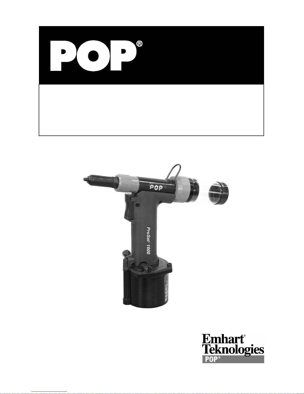
ProSet® 1600 Series
Maintenance Manual
Rivet
Tool
Page 2

Contents
Introduction...............................................................................................................................................2
Safety Instructions....................................................................................................................................3
Specifications...........................................................................................................................................4
Packaged Accessories..........................................................................................................................4
Tool Requirements................................................................................................................................4
ProSet® 1600 Tool Dimensions.............................................................................................................5
Common Nosepieces............................................................................................................................6
Basic Tool Operation ................................................................................................................................6
Front End Service.................................................................................................................................7
Mandrel Collection System (MCS) – ProSet® 1600 MCS .....................................................................8
Cleaning the Collector Silencer.............................................................................................................8
T ool Assembly T orqu e Requirements....................................................................................................9
ProSet® 1600/1600MCS Diagram..........................................................................................................10
Parts List ................................................................................................................................................12
Hydraulic Oil Charging Procedure..........................................................................................................14
Maintenance...........................................................................................................................................15
Safety Data.............................................................................................................................................16
Troubleshooting......................................................................................... .............................................17
EC Declaration of Conformity.................................................................................................................18
Introduction
®
ProSet® 1600 tools are light weight Air/Hydraulic rivet setting tools recommended for use with genuine
POP
®
Brand Rivets per following chart:
POP
Rivet Type
Material
(Body – Mandrel)
Al – Al 9 9 9
Open End & MultiGrip
Closed End
LSR Rivets Al – Al 9 9 9
HR™ Rivets St – St 9 9
T - Rivet Al – St 9 9 9
Self Plugger St – St 9 9
Al: Aluminum, St: Steel, SS: Stainless Steel, Cu: Cooper, Mo: Monel
(*) Use FAN239-176 Jaw pusher set up.
(†) Exclude MultiGrip
() Set air pressure at 90 psi (6.2 bar).
Al – St / SS 9 9 9
St – St 9 9 9
SS – SS; Mo – St /SS 9 9
Al – Al 9 9 9
Al – St / SS; Cu – St 9 9 9
St – St 9 9
SS – SS 9 9
(*)
3/32”
[2.4 mm]
Rivet Diame ter
1/8”
[3.0 - 3.2 mm]
5/32”
[4.0 mm]
(†)
()
Page 2 Emhart Teknologies - 50 Shelton Technology Center, Shelton CT 06484 - Tel. (203) 924-9341 - Fax (800) 225-5614
Page 3

Safety Instructions
TO INSURE PROPER FUNCTIONING AND SAFE OPERATION READ THIS MANUAL
CAREFULLY BEFORE SETTING UP OR OPERATING THE POP® ProSet™ 1600 SERIES TOOLS
1. DO NOT use this tool in a manner other than that recommended by Emhart Teknologies.
2. Always wear eye protection when using or when near a tool that is in use.
3. This tool is NOT designed for use in explosive atmospheres.
4. Inspect tool for damage before connecting to air supply including all air connections.
5. Trained personnel must perform tool repair and/or maintenance at the prescribed intervals.
6. Disconnect the air supply when adjusting, servicing or removing any part of the tool.
7. Keep fingers off the trigger when connecting the air supply or if the air supply fails.
8. Keep fingers away from the front of the tool when connecting the air supply or setting rivets.
9. DO NOT point the tool at anyone.
10. DO NOT operate tool with the nose housing removed.
11. DO NOT operate tool without the Deflector or Collector.
12. DO NOT modify the tool in any way. Modification will make void any applicable warranties
and could result in damage to the tool or physical injury to the user.
13. DO NOT look into the tool from the front or the back during use or when connected to air
supply.
14. The operating pressure must not exceed 100 psi (6.9 bar).
15. DO NOT direct tool exhaust towards anyone.
16. Wash hands if exposed to hydraulic fluid or lubricant.
17. Keep hair, fingers and loose clothing away from moving parts of the tool.
Emhart Teknologies - 50 Shelton Technology Center, Shelton CT 06484 - Tel. (203) 924-9341 - Fax (800) 225-5614 Page 3
Page 4

Specifications
ProSet® 1600 ProSet® 1600MCS
Weight
Length
Height
Stroke
Air Consumption
Pulling Force
Noise Level
Vibration Level
Qty Item PROSET1600 PROSET1600MCS Part No.
2.15 lbs. (0.98 kg) 2.30 lbs. (1.05 kg)
10.83” (275 mm) 10.71” (272 mm)
8.94” (227 mm) 8.94” (227 mm)
0.71” (18 mm) 0.71” 18 mm)
0.043 cu. ft. per rivet
(1.22
l per rivet)
1090 lbs. @ 90 psi (4850 N @ 0.62 MPa)
= 80.2 dB(A), LWA = 85.0 dB(A), L
L
Aeq,T
0.54 m/s
2
, Time to 2.5 m/s2 > 24hrs (EAV)
2.47 scfm (m ax.)
(70 l /min (max.))
= 110.4 dB(C)
Peak
Packaged Accessories
1 ProSet® 1600 Rivet Tool
1 Operating Instructions
1 Maintenance Manual
1 Nosepiece for 3 size open end rivets
1 Nosepiece for 4 size open end rivets Installed Installed PRN414
1 Nosepiece for 5 size open end rivets
1 Jaw Pusher (Assy.) for 3/32” rivets
1 Air Line Assembly
1 4 mm Hex. Socket Screw Key
1 Warranty Card
9
9 9
9 9
9 9
9 9
9 9
9 9
9 9
9 9
9
P449
P513
PRN314
PRN514
FAN239-176
FAN239-157
DPN239-139
FG2184
Tool Requirements
Air supply *
Recommended Operating Pressure 72.5-90 psi (0.5-0.62 MPa) dry, filtered
Maximum Operating Pressure 100 psi (0.69 MPa) dry, filtered
Hydraulic Oil **
Jaw Lubricant **
Seal Lubric ant **
POP
POP
POP
®
®
®
6 scfm (150
p/n: PRG540-130 [1 qt. (.945 ml)]
p/n: PRG510-130 [6 oz. (177 ml)]
p/n: PSA075508P [1 ¾ oz. (54 g)]
l /min) Minimum
(*) Note: For best results and long service life, use dry, filtered air supply.
(**) Note: See lubricant safety information.
Page 4 Emhart Teknologies - 50 Shelton Technology Center, Shelton CT 06484 - Tel. (203) 924-9341 - Fax (800) 225-5614
Page 5
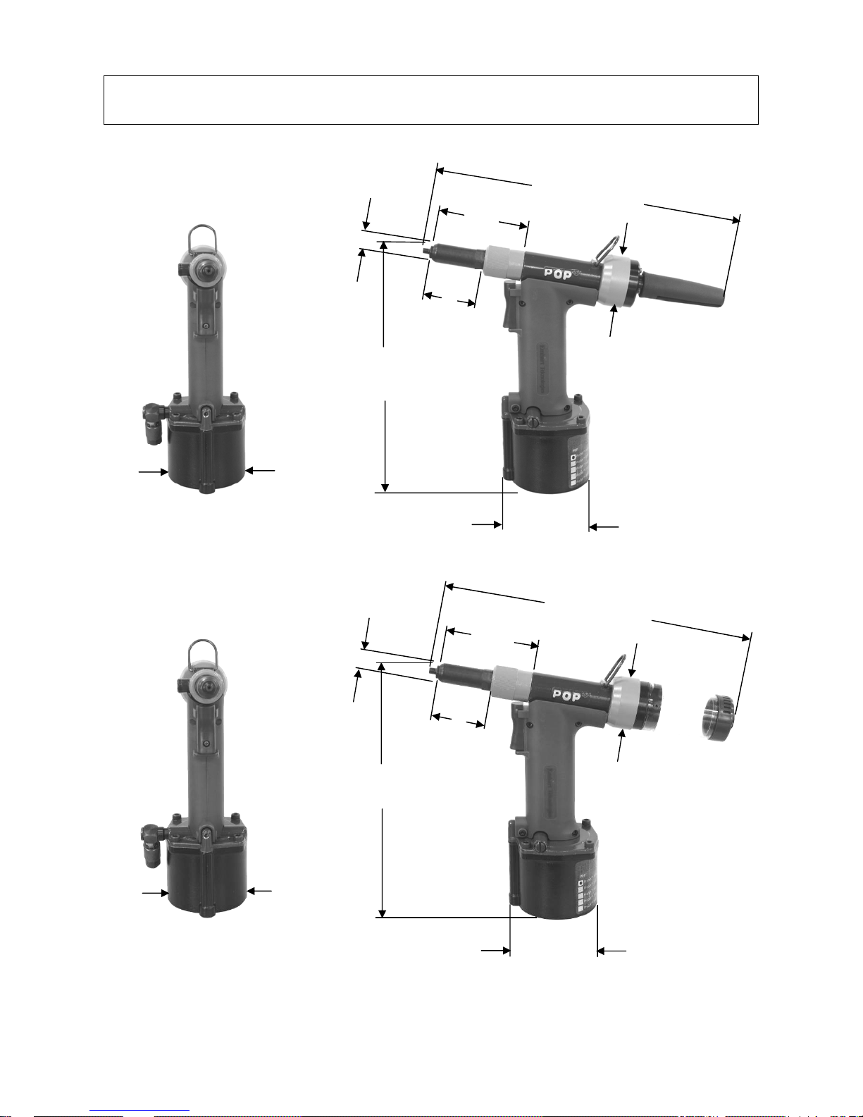
ProSet® 1600 Tool Dimensions
10.83” (275 mm)
3.3” (82 mm)
.682” (17.3 mm)
1.82” (46.3 mm)
1.83” (46.5 mm)
8.94” (227 mm)
2.99” (76 mm)
.682” (17.3 mm)
ProSet® 1600
3.27” (83 mm)
10.71” (272 mm)
3.23” (82 mm)
1.82” (46.3 mm)
1.83” (46.5 mm)
8.94” (227 mm)
2.99” (76 mm)
Emhart Teknologies - 50 Shelton Technology Center, Shelton CT 06484 - Tel. (203) 924-9341 - Fax (800) 225-5614 Page 5
ProSet® 1600 MCS
3.27” (83 mm)
Page 6
Common Nosepieces
A
Closed End HR Rivets
Rivet Diameter Open End
Steel Mandrel
Aluminum
Mandrel
Aluminum
Body
Steel
Body
2.0 mm PRN214 - - - 3/32” (2.4 mm) PRN314* - - - - FAN239-176*
Jaw Pusher
FAN239-176*
(PRG402-02 - JAWS)
1/8” (3.2 mm) or
7/64” (2.8 mm)
PRN414* PRN424 PRN434 PRN414* PRN4K
DPN239-144*
5/32” (4.0 mm) PRN514* PRN524 PRN534 PRN514* -
* Included with the tool
Use FAN239-176 instead of DPN239-144 (installed) when using 3/32” (2.4mm) or smaller diameter
rivets.
Basic Tool Operation
Before operating the tool check the following:
Ins pect t ool for damage or leaking oil – do not use tool if it is damaged or leaking oil.
Chec k that correct nosepiece is fitted and tightened to 60 - 65 in-lbs [6.8 – 7.3 N-m] torque.
Chec k that the nose housing nut (8) is tight – hand tighten only.
Connec t tool to air supply – see air supply requirements (page 4).
Fit Mandrel Collector (96) – (MCS tool only).
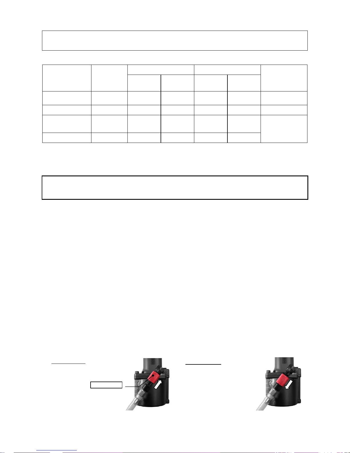
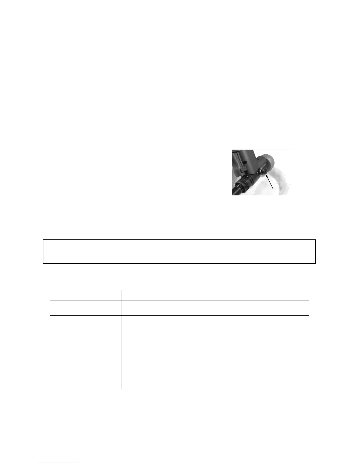
Open air s upply valve by Sliding red OS Sleeve (93) on side of tool (see note below).
Insert rivet into nosepiece.
Position rivet in work piece.
Pull trigger to set rivet.
Release trigger – if equipped, MCS suction will draw mandrel into the collector.
! Note: The ProSet
®
1600 has an OS (Open-Shut) Valve for switching the air supply ON and OFF to
save air when the tool is not in use.
Air Supp ly ON: Open OS Valve
by sliding OS Sleeve in the
direction shown (up).
OS Sleeve
Page 6 Emhart Teknologies - 50 Shelton Technology Center, Shelton CT 06484 - Tel. (203) 924-9341 - Fax (800) 225-5614
ir Supply OFF: Close OS Valve
by sliding OS Sleeve in the
direction shown (down).
Page 7
Front End Service
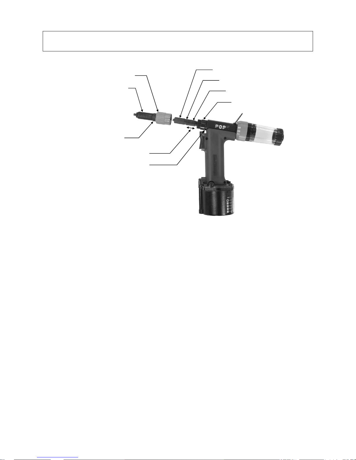
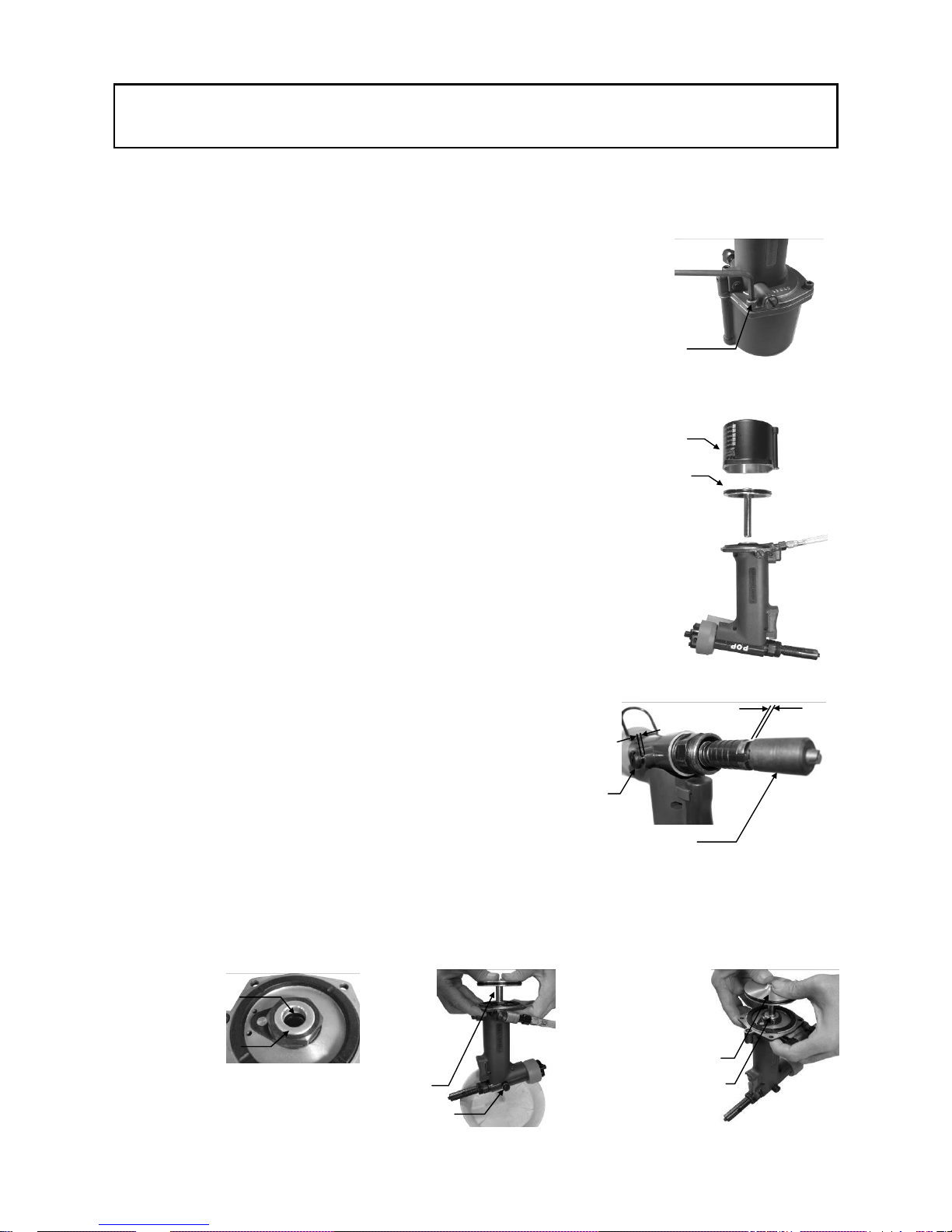
Nose Housing Nut
Nose Housing
Wrench Flat
Jaw Guide Lock motion
O-Ring
For optimum tool performance, Fron t-End Service should be perfor med regularly as per the “Preventative Maintenance
Schedule”.
Jaw Guide
Pulling Head
Jaw Guide Lock
Housing Adapter
! Note: UNPLUG AIR SUPPLY while servicing front-end to avoid INJURY.
1. REMOVE NOSE HOUSING:
Unscrew the Nose Housing Nut by hand and
slide Nose Housing off the tool.
2. REMOVE JAW GUIDE TO ACCESS JAWS
AND INTERNAL PARTS:
Pull back the Jaw Guide Lock to disengage the
Jaw Guide Lock Teeth and unscrew and remove
the Jaw Guide.
Remove Jaws, Jaw Pusher, and Jaw Pusher
Spring for servicing.
3. CLEAN PARTS:
Clean Jaws, Jaw Guide, Jaw Pusher, Spring
and thread area of the Pulling Head.
Apply Seal Lube to outside surface of Jaws and
inside surface of the Jaw Guide.
4. REASSEMBLY OF INTERNAL PARTS AND JAW
GUIDE:
Place the Jaws into the Jaw Guide and slide the Jaw
Pusher Spring and Jaw Pusher into the Pulling Head.
Apply a small amount of Seal lubricant to the Pulling
Head threads and Jaw Guide Lock teeth. Screw the Jaw
Guide onto the Pulling Head until the teeth on the Jaw
Guide Lock stop the Jaw Guide rotating.
Apply Jaw lubricant to the Jaw area by submerging the
assembled Jaw Guide into Jaw lube about 1 in. (25mm).
Clean off excess Jaw Lube from the outside of the Jaw
Guide.
5. REINSTALL NOSE HOUSING ASSEMBLY:
Refit the Nose Housing and Hand-tighten the Nose
Housing Nut securely against the O-Ring. If the Nut is
not tightened sufficiently against the O-Ring there may
be a loss of suction.
Emhart Teknologies - 50 Shelton Technology Center, Shelton CT 06484 - Tel. (203) 924-9341 - Fax (800) 225-5614 Page 7
Page 8
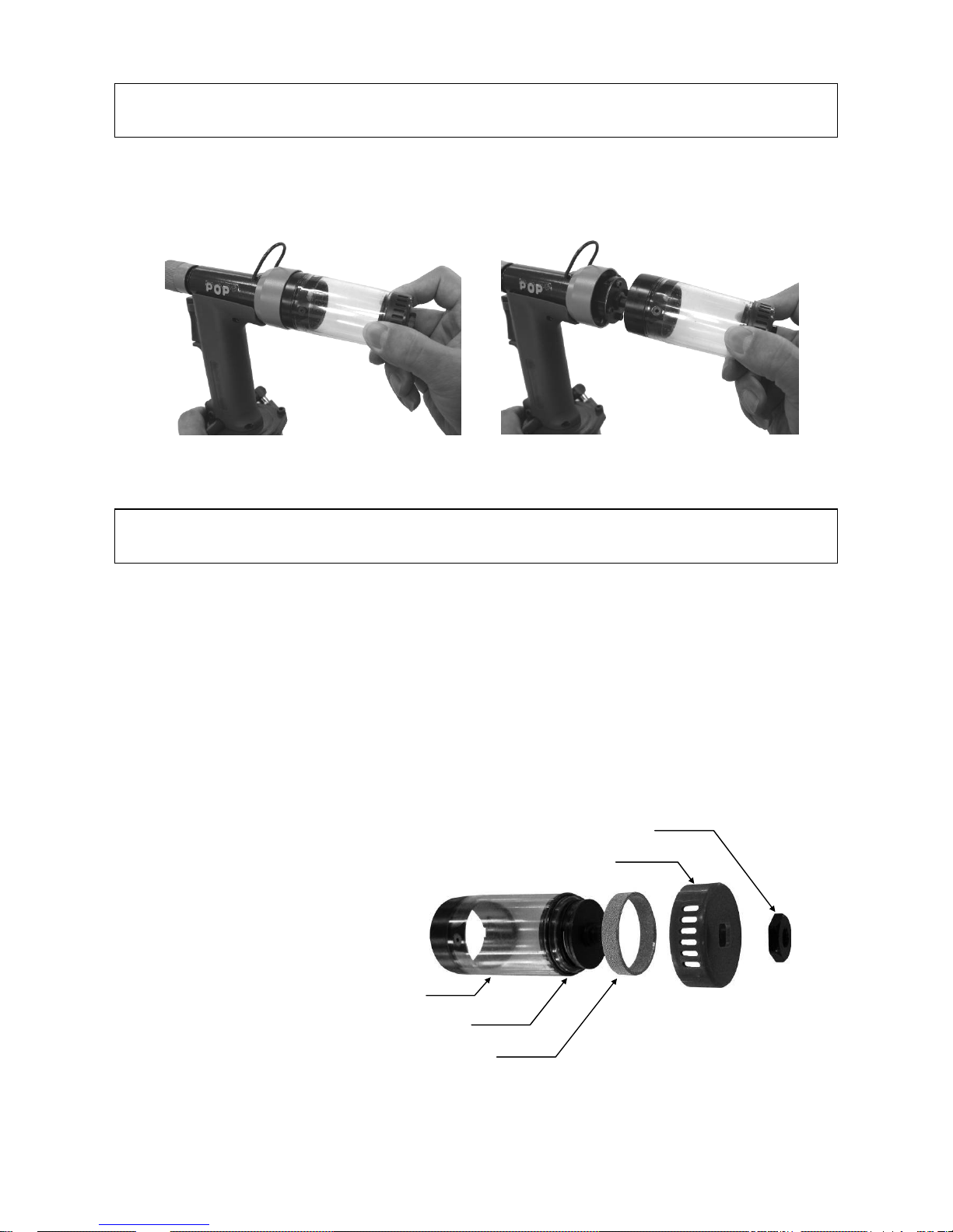
Mandrel Collection System (MCS) – ProSet® 1600 MCS
For safety purposes, removing the Collector from the tool automatically turns the MCS suction OFF. Refitting
the Collector turns the MCS suction ON.
MCS suction ON
MCS suction OFF
Cleaning the Collector Silencer
For optimum performance, the Collector Silencer should be cleaned at regular intervals as per the
“Preventative Maintenance Schedule”.
! Note: UNPLUG AIR SUPPLY while servicing Collector to avoid INJURY.
1. CLEAN THE COLLECTOR :
• Remove and empty the Collector (96) by turning counterclockwise.
• Remove the Collector End Nut (106) (17mm wrench) and remove the Collector End Cap (105).
• Remove the Collect or Silencer (103).
• Clean and remove debris from all components.
Collector Body (101)
Collector End (104)
Collector Silencer (103)
Collector End Nut (106)
Collector End Cap (105)
Page 8 Emhart Teknologies - 50 Shelton Technology Center, Shelton CT 06484 - Tel. (203) 924-9341 - Fax (800) 225-5614
Page 9
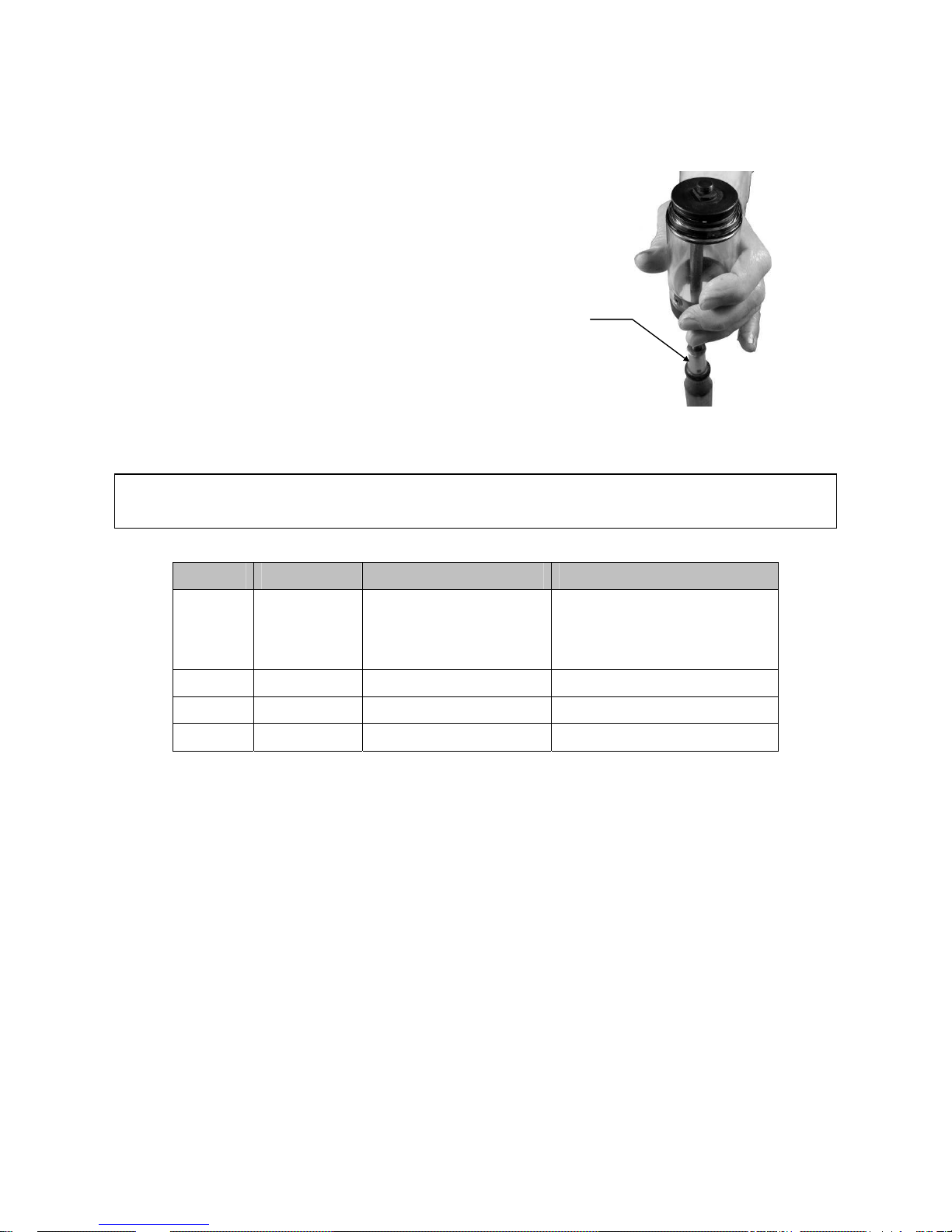
2. RE-ASSEMBLE THE COLLECTOR :
• Secure Collector End (104) to Collector Body (101). Use a screwdriver or similar tool to hold the
Collector End in place during re-assembly (see picture below).
• Place the Collector Silencer (103) onto the Collector End (104).
• Place Collector End Cap (105) on Collector Body End (104).
• Install and tighten Collector End Nut (106) on Collector End (104).
Screwdriver
Tool Assembly Torque Requirements
Item Part No. Description Torque Value
1
119
120
PRN414
PRN314
PRN514
Nosepiece 4 size
Nosepiece 3 size
Nosepiece 5 size
60 – 65 in-lbs (6.8 – 7.3 N-m)
51 DPN239-053 Sleeve Lower 35 - 39 ft-lbs (47 - 53 N-m)
61 DPN239-063 Sleeve Lock Nut 31 - 35 ft-lbs (42 - 48 N-m)
88 DPN907-003 Socket Head Cap Screw 46 - 51 in-lbs (5.2 – 5.8 N-m)
See exploded Tool Diagram
Emhart Teknologies - 50 Shelton Technology Center, Shelton CT 06484 - Tel. (203) 924-9341 - Fax (800) 225-5614 Page 9
Page 10
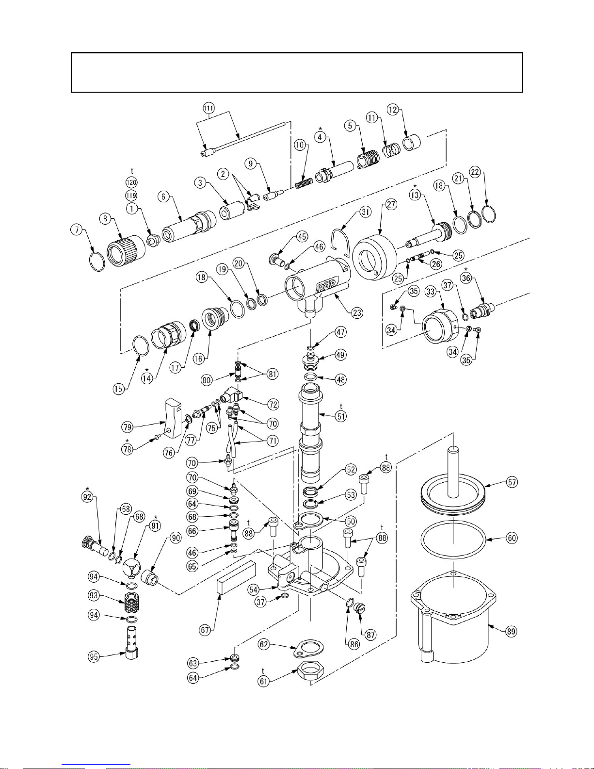
ProSet® 1600/1600MCS Diagram
Use with 3 size ri vets
(*) These items require Loctite
(†) These items have a specific tightening torque as indicated in the “Tool Assembly Torque Requirements” table.
Page 10 Emhart Teknologies - 50 Shelton Technology Center, Shelton CT 06484 - Tel. (203) 924-9341 - Fax (800) 225-5614
®
242 adhesive.
Page 11
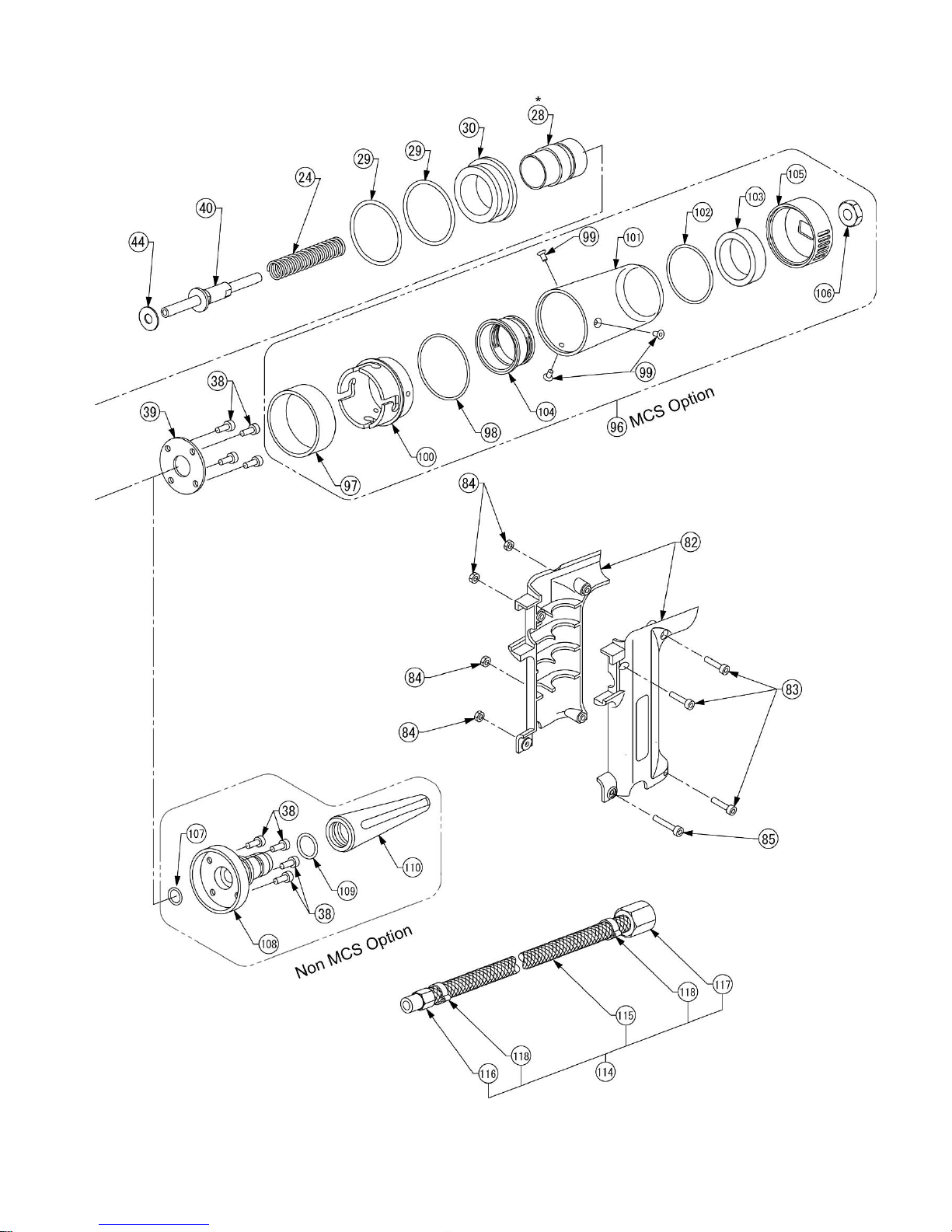
Emhart Teknologies - 50 Shelton Technology Center, Shelton CT 06484 - Tel. (203) 924-9341 - Fax (800) 225-5614 Page 11
Page 12

Parts List
Item Part No. Description 1600 1600
MCS
Item Part No. Description 1600 1600
MCS
1 PRN414 Nosepiece 4 size 1 1
2 PRG402-8A Jaws 1set(2) 1set(2)
3 DPN239-006 Jaw Guide 1 1
4 DPN239-007 Pulling Head 1 1
5 DPN239-008 Jaw Guide Lock 1 1
6 DPN239-009 Nose Housing 1 1
7 DPN900-001 O-Ring 1 1
8 DPN239-011 Nose Housing Nut 1 1
9 DPN239-144 Jaw Pusher 1 1
10 DPN901-001 Jaw Pusher Spring 1 1
11 DPN901-002 Spring 1 1
12 DPN239-018 Spring Receiver 1 1
13 DPN239-019 Hydraulic Piston 1 1
14 DPN239-020 Housing Adapter 1 1
15 DPN900-002 O-Ring 1 1
16 DPN239-022 Rod Seal Case 1 1
17 DPN908-001 Scraper 1 1
18 DPN900-003 O-Ring 2 2
19 DPN908-002 B.U-Ring 1 1
20 DPN908-003 Penta Seal 1 1
21 DPN908-004 B.U-Ring 1 1
22 DPN900-004 O-Ring 1 1
23 DPN239-029 Handle Upper 1 1
24 DPN901-003 Return Spring 1 1
25 DPN900-005 O-Ring 2 2
26 DPN239-111 MCS Valve Rod 1 1
27 DPN239-112 MCS Cap 1 1
28 DPN239-034 End Cap Adapter 1 1
29 DPN900-019 O-Ring 2 2
30 DPN239-036 Slider 1 1
31 DPN239-181 Hook 1 1
33 DPN239-153 End Cap 1 1
34 DPN239-116 Collar 2 2
35 DPN239-154 Collar Screw 2 2
36 DPN239-118 Ejector Guide 1 1
37 DPN900-006 O-Ring 2 2
38 DPN907-002
39 DPN239-119 End Cap Plate - 1
40 FAN239-043 Ejector Assembly 1 1
44 DPN239-108 Packing 1 1
45 DPN239-047 Fill Screw 1 1
46 DPN900-007 O-Ring 2 2
47 DPN900-008 O-Ring 1 1
48 DPN900-009 O-Ring 1 1
49 DPN239-147 Sleeve Upper 1 1
50 DPN239-052 Upper Plate 1 1
51 DPN239-053 Sleeve Lower 1 1
52 DPN908-005 Penta Seal 1 1
53 DPN908-006 B.U-Ring 1 1
54 FAN239-148 Handle Lower Assy 1 1
57 FAN239-059 Air Piston Assembly 1 1
60 DPN900-010 O-Ring 1 1
61 DPN239-063 Sleeve Lock Nut 1 1
62 DPN239-064 Bottom Plate 1 1
63 DPN239-065 J Valve Cap 1 1
Socket Hd Cap Screw
4 4
64 DPN900-011 O-Ring 2 2
65 DPN900-012 O-Ring 1 1
66 DPN239-068 J Valve Rod 1 1
67 DPN239-069 EXT Silencer 1 1
68 DPN900-013 O-Ring 3 3
69 DPN239-071 Valve Stopper 1 1
70 DPN239-120 Fitting 4 4
71 DPN239-121 Air Tube 2 2
72 FAN239-074 S.V Case Assembly 1 1
75 DPN900-014 O-Ring 2 2
76 DPN902-001 Retaining Ring 1 1
77 DPN239-078 S Valve Rod 1 1
78 DPN906-001 Button Hd Cap Screw 1 1
79 DPN239-150 Trigger 1 1
80 DPN239-083 Connect Tube 1 1
81 DPN900-015 O-Ring 2 2
82 DPN239-151 Handle Assembly 1 1
83 DPN907-001
84 DPN239-086 Hexagon Nut 4 4
85 DPN907-004
86 DPN900-016 O-Ring 1 1
87 DPN239-089 Plug 1 1
88 DPN907-003
89 DPN239-091 Chamber 1 1
90 DPN239-126 R Joint Spacer 1 1
91 DPN239-093 R Joint 1 1
92 DPN239-127 R Joint Adapter 1 1
93 DPN239-095 O S Slider 1 1
94 DPN900-017 O-Ring 2 2
95 DPN239-097 O S Joi n t 1 1
96 FAN239-166 Collector Assembly - 1
97 DPN239-098 Collector Lock Collar - 1
98 DPN900-018 O-Ring - 1
99 DPN903-001 Flat Head Cap Screw - 3
100 DPN239-155 Collector Lock - 1
101 DPN239-130 Collector Body - 1
102 DPN900-020 O-Ring - 1
103 DPN239-168 Collector Silencer - 1
104 DPN239-156 Collector End - 1
105 DPN239-167 Collector End Cap - 1
106 DPN239-152 Collector End Nut - 1
107 DPN900-021 O-Ring 1 108 DPN239-163 Deflector Adapter 1 109 DPN900-022 O-Ring 1 110 PRG510-56 Deflector 1 111 FAN239-176 Jaw Pusher Assy 1 1
114 FAN239-157 Air Line Assembly 1 1
115 DPN239-158 Air Line 1 1
116 DPN239-159 Air Line Fitting 1 1
117 DPN239-160 Hose Female Fitting 1 1
118 PRG540-45 O-Clamp (0911) 2 2
119 PRN314 Nosepiece 3 size 1 1
120 PRN514 Nosepiece 5 size 1 1
NS DPN239-139 HS Screw key - M4 1 1
Socket Hd Cap Screw
Socket Hd Cap Screw
Socket Hd Cap Screw
3 3
1 1
4 4
Page 12 Emhart Teknologies - 50 Shelton Technology Center, Shelton CT 06484 - Tel. (203) 924-9341 - Fax (800) 225-5614
Page 13

Optional Parts and Kits are also available separately.
Part No. Description
PRN214 Nose piece for 2.0 mm rivet (Micro Rivets)
PRG402-02 Jaws for 2.0 mm rivet (Micro Rivets)
DPN239-110 17mm Hex. Socket screw key for End
ProSet® 1600 Front End Extension
FAN239-174
2 PRG402-8A Jaws 1
3 DPN239-006 Jaw Guide 1
5 DPN239-008 Jaw Guide Lock 1
7 DPN900-001 O-Ring 1
8 DPN239-011 Nose Housing Nut 1
9 DPN239-144 Jaw Pusher 1
10 DPN901-001 Jaw Pusher Spring 1
11 DPN901-002 Spring 1
DPN239-169 Nose Housing 1
DPN239-170 Pulling Head Extension 1
DPN239-171 Pulling Head Joint 1
Kit – 5” [127mm] length
Contains:
Part No. Description
37 DPN900-006 O-Ring 2
46 DPN900-007 O-Ring 1
60 DPN900-010 O-Ring 1
68 DPN900-013 O-Ring 2
94 DPN900-017 O-Ring 2
17 DPN908-001 Scraper 1
19 DPN908-002 B.U-Ring 1
20 DPN908-003 Penta Seal 1
21 DPN908-004 B.U-Ring 1
52 DPN908-005 Penta Seal 1
53 DPN908-006 B.U-Ring 1
ProSet® 1600 Adaptor Kit for
FAN203-408
MCS5000-78 Adapter Cap 1
MCS5000-81 Strain Relief 1
PRT5250-24 Tapered Bushing 1
MCS5000 (remote MCS)
Contains:
FAN239-172 Jaw Pusher (Assembly) 1
®
FAN239-175
7 DPN900-001 O-Ring 1
15 DPN900-002 O-Ring 1
18 DPN900-003 O-Ring 2
22 DPN900-004 O-Ring 1
25 DPN900-005 O-Ring 2
ProSet
Contains:
1600/1600MCS Seal Kit
PRT5250-26 Tapered Bushing 1
PRT5250-98 Fitting for 5 size rivets 1
PRT5250-99 Fitting for 4 size rivets 1
®
FAN239-177
39 DPN239-119 End Cap Plate 1
96 FAN239-166 Collector Assembly 1
ProSet
Contains:
1600 MCS Retrofit Kit
RP4-486 RP4/RP5 Receptacle
Emhart Teknologies - 50 Shelton Technology Center, Shelton CT 06484 - Tel. (203) 924-9341 - Fax (800) 225-5614 Page 13
Page 14
(88)
Hydraulic Oil Charging Procedure
! IMPORTANT. TOOL MUST BE DISCONNECTED FROM THE AIR SUPPLY. USE ONLY APPROVED
HYDRAULIC OIL SPECIFIED IN THIS MANUAL.
1. Disconnect from air supply.
2. Remove Nose Housing (6) and Collector (96).
3. Remove four Socket Head Cap Screws (88) using 4mm Hex-Key
wrench (accessory). (Fig. 1)
4. Turn tool upside down and remove Chamber (89).
Then pull out Air Piston Assembly (57). (Fig. 2)
5. Drain the oil from the tool into a waste oil container.
6. Clean the dirt off the Air Piston Assembly (57) and inner
Chamber (89) with a clean rag.
Apply a thin layer of Seal lubricant to inner Chamber.
7. Loosen Jaw Guide (3) approximately 3 full turns or a 0.12"
(3mm) gap and loosen Fill Screw (45) approximately 3 - 3½ full
turns or a 0.14"(3.6mm) gap (Fig. 3).
8. Secure the tool upside down again and pour hydraulic oil into
Sleeve Lower (51) to the level of the Backup Ring (white part)
(53). (Fig. 4)
9. Push Air Piston Assembly (57) into Sleeve Lower (51) to
half-way point so that dirty hydraulic oil and air bubbles will
come out from the loosened Fill Screw (45).
Hold Air Piston Assembly until no more oil or bubbles come out.
(Fig. 5)
10. Loosely tighten Fill Screw (45) and pull out Air Piston
Assembly (57).
11. Pour more hydraulic oil into Sleeve Lower (51) to the level
of the Backup Ring and push Air Piston Assembl y (57) into
Sleeve Lower (51). Push Air Piston inwards then outwards
5-6 times in a slow, constant motion.
Then pull it out and check for bubbles rising to the oil
surface.
If there are still bubbles, repeat the proc edure until there
are no more bubbles (Fig. 6).
It may be necessary to repeat this procedure 2-3 times to bleed all bubbles from the oil.
If after 3 attempts there are still bubbles in the oil, go back to No.5 and start again by draining the hydraulic oil.
`
Backup Ring (53)
Sleeve Lower (51)
Fig. 4
Air Piston Assembly (57)
Fill Screw (45)
Fig. 5
Fill Screw (45)
Socket Head Cap
Screw
Chamber (89)
Air Piston Assembly (57)
Fig. 3
0.14"(3.6mm)
Jaw guide (3)
Air Piston Assembly (57)
Sleeve Lower (51)
Fig. 1
Fig. 2
0.12"(3mm)
Fig. 6
Page 14 Emhart Teknologies - 50 Shelton Technology Center, Shelton CT 06484 - Tel. (203) 924-9341 - Fax (800) 225-5614
Page 15
12. When there are no more bubbles in the oil, top off the hydraulic oil in the Sleeve Lower (51) to t he lev el of the Ba ckup
Ring (53).
13. Make sure the Jaw Guide (3) is loose (see Step 7). Push the Air Piston Assembly (57) into the Sleeve Lower (51) to
the half-way point. While holding t he Air Piston at the half-w ay point, replace the Nose Housing and hand tighten.
14. With a clean rag, wipe off any oil on the Air Pis ton Assembl y (57), Handle Lo wer Assembly (54) , and Sleev e Lower
(51). Put Chamber (89) over Air Piston Assembly (57) then turn the tool upright and tighten the four Socket Head
Cap Screws (88) to a Torque of 46 - 51 in-lbs (5.2 – 5.8 N-m).
15. Remove the Nose Housing (6), and t ighten the Jaw Guide (3) by hand until it stops.
16. Loosen the Fill Screw (45) approximately 3 - 3½ full turns or a 0.14"(3.6mm) gap to allow excess hydraulic oil and
bubbles to escape. When no more oil comes out, tighten the Fill Screw (Fig. 7).
17. Wipe off any dirt and oil on the tool.
18. Replace the Nose Housing (6) and Collector (96).
Fig. 7
Fill Screw (45)
Note: During assembly and disassembly, do not allow any metal swarf or dirt into the Hydraulic
Oil and inner Chamber.
Maintenance
Preventative Maintenance Schedule
Item Action Frequency
Clean and lubricate Front
End of tool
Inspect jaws
Collector
Note: Only use Emhart specified greases and lubricants
See “Front End Service”
Look for broken jaws and
damage or wear on jaw teeth.
Empty Collector
Clean Collector Silencer
1 x per day or
5,000 rivet settings.
During “Front End Service” or when jaws
slip on mandrel.
When the quantity of stored spent
Mandrels starts to interfere with
mandrels entering the Collector.
(Storage quantity depends on rivet –
approx. 75-90 5/32” (4.0mm) rivets).
Once a week or when MCS suction will
not pull spent mandrels into the
Collector.
Emhart Teknologies - 50 Shelton Technology Center, Shelton CT 06484 - Tel. (203) 924-9341 - Fax (800) 225-5614 Page 15
Page 16

Safety Data
SEAL LUBE
LUBRIPLATE
Manufactured by:
Fiske Brothers Refining Co.
Phone: (419) 691-2491
Emergency: (800) 255-3924
AL VANIA® EP Grease 1
Prod Code: 71124
Manufactured by:
Shell Oil Products
Phone: (877) 276-7285
MSDS#: 57072E-5
First Aid:
SKIN:
Remove any contaminated clothing and
wash wit h soap and warm water. I f
injected by high pressure under skin,
regardless of the appearance of its size,
contact a physician IMMEDIATELY.
Delay may cause loss of affected part
of body.
INGESTION:
Call a physician immediately. Do not
induce vomiting.
EYES:
Flush with clear water for 15 minutes or
until irritation subsides. If irritation
persists, consult a physic ian.
Fire:
FLASH POINT: COC- 400°F
Cool exposed containers with water.
Use foam, dry chemical, carbon dioxide
or water spray.
Environment:
WASTE DISPOSAL:
Assure conformity with applicable
disposal regulations. Dispose of
absorbed material at an approved
waste disposal facility or site.
SPILLAGE:
Scrape up grease, wash remainder with
suitable petroleum solvent or add
absorbent.
Handling/ Storage:
Keep containers closed when not in
use. Do not handle or store near heat,
sparks, flame or strong oxidants.
Lubriplate® is a registered trademark of Fiske
Brothers Refining Company.
Please refer to the actual MSDS for complete safety and handling
information. These can be obtained from the point of purchase.
(P/N: PSA075508P)
®
130-AA
JAW LUBE (P/N: PRG510-130)
SUNPAR 107
Manufactured By:
Sunoco, Inc.
Emergency Phone: (800) 424-9300
First Aid:
SKIN:
Wash with soap and water until no
odor remains. If redness or
swelling develops, obtain medical
assistance. Wash cloths before
reuse.
INGESTION:
Do not induce vomiting! Do not
give liquids! Obtain emergency
medical attention. Small amounts
that accidentally enter mouth
should be rinsed out unti l taste of it
is gone.
EYES:
Flush with water.
Fire:
FLASH POINT: Greater than 200°F
Can be made to burn. Use water
spray, regular foam, dry chemical or
carbon dioxide.
Environment:
WASTE DISPOSAL:
Do not flush to drain or storm sewer.
Contract authorized disposal
service.
SPILLAGE:
Contain Spill. Absorb onto inert
material. Shovel, sweep or
vacuum spill.
Handling/ Storage:
NFPA Class IIIB Storage. Avoid
prolonged breathing of mist or
vapor. Avoid prolonged or
repeated contact with skin. Avoid
contact with eyes. Wash thoroughly
after handling.
HYDRAULIC OIL (P/N: PRG540-130)
MOBIL DTE 26
Manufactured By:
ExxonMobil Corporation
Emergency Phone: (609) 737-4411
MSDS Fax on Demand:
(613) 228-1467 MSDS # 602649-00
Shell TELLUS 68
Manufactured By:
SOPUS Products
Health Information: (877) 504-9351
MSDS Assistance:
(877) 276-7285 MSDS # 402288L-0
Distributed By:
Emhart Teknologies
Phone: (203) 924-9341
First Aid:
SKIN:
Remove contaminated cloth ing and
shoes and wipe excess from skin.
Flush skin with water, then wash with
soap and water. If irritation occurs,
get medical attention.
INGESTION:
Do not induce vomiting. In general, no
treatment is necessary unless large
quantities of product are ingested.
However, get medical attention.
EYES:
Flush with water. If irritation occurs, get
medical attention.
Fire:
FLASH POINT: 390°F/198.9°C
Material will float and can be re-ign it e d
on the surface of water. Use water fog,
‘alcohol foam’, dry chemical or carbon
dioxide (CO2) to extingu ish flames. Do
not use a direct stream of water.
Environment:
SPILLAGE:
Soak up residue with an absorbent such
as clay, sand or other suitable material.
Place in a non-leaking container and
seal tightly for prope r disposal.
Handling:
Wash with soap and water before
eating, drinking, smoking, applying
cosmetics or using toilet. Properly
dispose of leather articles such as
shoes or belts that cannot be
decontaminated. Use in a well
ventilated area.
Storage:
Store in a cool, dry place with adequate
ventilation. Keep away from open
flames and high temperatures.
Page 16 Emhart Teknologies - 50 Shelton Technology Center, Shelton CT 06484 - Tel. (203) 924-9341 - Fax (800) 225-5614
Page 17

Symptom Probable Cause Remedy
TOOL FAILS TO OPERATE
TOOL NOT RETURNING
Troubleshooting
Tool not connected to air supply.
OS Valve is in “OFF” position.
Insufficient air pr essure.
Air pressure is too high.
Tool is low on hydraulic fluid.
Possible jam due to debris in Nose Housing. Perform “Front End Service” and check for debris
Connect to recommended air supply source.
Slide OS Valve to ON position.
Adjust air supply pressure.
Adjust air supply pressure.
Service tool by qualified service personnel.
or damage.
TOOL LOSING STROKE
JAWS SLIPPING ON MANDRELS
JAWS FAIL TO OPEN
MANDREL STICKING IN JAWS
RIVET FAILS TO INSERT INTO
NOSEPIECE
RIVET MANDREL DOES NOT
BREAK
MCS NOT WORKING
LOW VACUUM
Tool low on hydraulic fluid. Service tool by qualified service personnel.
Jaws dirty or need lubrication.
Jaws worn.
Dirty Nose Housing, Jaws or Jaw Guide.
Nose Housing loose.
Excess hydraulic oil in tool.
Jaws dirty or need lubrication.
Incorrect nosepiece.
Shear ring stuck in hole of nosepiece.
Rivet not fully set.
Mandrel break load requirement too high.
Insufficient air pr essure.
Tool not connected to air supply.
Collector not tight or missing.
Mandrel path blocked.
Dirty Silencer.
Collector is full of mandrels.
Insufficient air pr essure.
Clean and lube jaws.
Replace jaws.
Perform “Front End Service” and clean inside of
Nose Housing.
Tighten Nose Housing.
Service tool by qualified service personnel.
Perform “Front End Service” to clean and
lubricate Jaws.
Install correct nosepiece.
Remove shear ring, check for the correct
Nosepiece and review application parameters to
ensure proper riveting.
Repeat stroke required, or change rivet.
Upgrade tool.
Adjust air supply pressure to recommended leve l.
Connect to recommended air supply source.
Check Collector.
Clear mandrel path.
Clean or change Silencer.
Discard the mandrels.
Adjust air supply pressure.
Emhart Teknologies - 50 Shelton Technology Center, Shelton CT 06484 - Tel. (203) 924-9341 - Fax (800) 225-5614 Page 17
Page 18
EC Declaration of Conformity
We, Emhart Teknologies
Tucker Fasteners Limited
Birmingham B42 1BP
United Kingdom.
Declare that:
ProSet® 1600
ProSet® 1600 MCS
Conforms to the following standards:
EN ISO 12100 part 1 and part 2 ISO prEN 15744
ISO 3744 EN 28662 - 1
ISO prEN 792 part 1 E N 12096
EN ISO 4871
Following the provisions of the Machine Directive 98/37/EEC which replaces Directive 89/392/EEC and its
amending Directives 91/368/EEC, 93/44/EEC and 93/68/EEC.
Signed: ____________________________________
Birmingham
st
1
. September 2008
Page 18 Emhart Teknologies - 50 Shelton Technology Center, Shelton CT 06484 - Tel. (203) 924-9341 - Fax (800) 225-5614
Eymard Chitty, Vice President, R&D
Page 19

Notes
Emhart Teknologies - 50 Shelton Technology Center, Shelton CT 06484 - Tel. (203) 924-9341 - Fax (800) 225-5614 Page 19
Page 20

THE AMERICAS
United States
50 Shelton Technology Center
P.O. Box 859
Shelton, CT 06484
USA
Tel. 203-924-9341
Fax. 800-225-5614
Canada
9870 boul. Du Golf
Anjou, Quebec H1J 2Y7
Canada
Tel. 514-351-0330
Fax. 514-351-0458
Brazil
Rua Ricardo Cavatton, 226 LAPA
CEP 05038-110 Sao Paulo, SP
Brazil
Tel. +55-11-3871-6460
Fax +55-11-3611-3508
México
Bosque de Radiatas No 42
Bosques de las Lomas
05120 México, D.F.
Tel. +52-555-326-7100
Fax. +52-555-326-7 141
EUROPE
Denmark
Farverland 1B
DK-2600 Glostrup
Denmark
Tel. +45-4484-1100
Fax. +45-4484-6212
Finland
Hyttmästargränden 4,
FlN-02780 ESBO
Finland
Tel. +358 9 8190060
Fax. +358 9 812428
France
ZA des Petits Carreaux
Bâtiment Haute Technologie No 8
2 bis, Avenue des Coquelicots
94385 Bonneuil-Sur-Marne
France
Tel. 33-1-5671-2424
Fax. 33-1-5671-2434
Norway
Postboks 153, Leirdal
1009 Oslo, Norway
Tel. +47 2290-9990
Fax. +47 2290-9980
Spain
Carretera M-300 Km 29,700
28802 Alcalá de Henares
Madrid, Spain
Tel. 34-91-887-1470
Fax. 34-91-882-3602
Sweden
Skjutbanevägen 6
SE-701 44 Örebro, Sweden
Tel. +46 19 2058000
Fax. +46 19 260038
United Kingdom
177 Walsall Road
Perry Barr
Birmingham, B42 1BP
United Kingdom
Tel. +44 (0) 121 331-2460
Fax. +44 (0) 121 356-1598
ASIA PACIFIC
Japan
Shuwa Kioicho Park Building 302
3-6 Kioicho, Chiyoda -Ku
Tokyo, 102-0094, Japan
Tel. 81-03-3265-7291
Fax. 81-03-3265-7298
Korea
Rm 609, Seorin Bldg.
45-15 Yeoido-Dong
Yeongdeungpo-Ku
Seoul, 150-891, R.O. Korea
Tel. 82-2-783-9226
Fax. 82-2-783-9228
P.R.China
488 Jia Tang Road
Jiading District
Shanghai 201807
People’s Republic of China
Tel. 86-21-5954-8626
Fax. 86-21-5954-8775
Visit our website at http://www.emhart.com
©2008 Emhart Teknologies Form No. P513 Rev. 2
(09/2008)
 Loading...