

Page 1
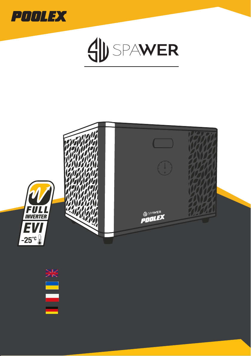
ICESPA 7
Installation and user manual
Instrukcja instalacji i obsługi
Installations und Gebrauchsanleitung
poolex.fr
Page 2

Dear customer,
Thank you for your purchase and your trust in our products.
Our products are the result of years of research in the design and manufacture of heat pumps for pools.
Our goal is to deliver high-quality products with exceptional performance.
We took great care to put together this manual so you can get the most out of your Poolex heat pump.
,
.
.
—
.
,
Poolex.
Szanowni Klienci,
dziękujemy za wybór naszych produktów oraz za zaufanie, jakim nas Państwo obdarzyli.
Nasze wyroby są rezultatem wieloletnich badań w dziedzinie projektowania i produkcji pomp ciepła do
basenów.
Naszym celem jest dostarczanie wysokiej jakości produktów o wyjątkowych parametrach
eksploatacyjnych.
Starannie przygotowaliśmy niniejszą instrukcję, aby mogli Państwo jak najefektywniej korzystać z
pompy ciepła Poolex.
Sehr geehrter Kunde,
Vielen Dank für Ihren Kauf und das damit verbundene Vertrauen in unsere Produkte.
Unsere Produkte sind das Ergebnis einer jahrelangen Forschungsarbeit auf dem Gebiet der Konstruktion
und Fertigung von Schwimmbecken-Wärmepumpen. Wir haben den Anspruch, Ihnen ein qualitativ hochwertiges Produkt mit hervorragenden Leistungseigenschaften zu liefern.
Die vorliegende Anleitung wurde mit größter Sorgfalt erstellt und soll Ihnen dabei helfen, die Vorzüge
Ihrer Poolex-Wärmepumpe bestmöglich zu nutzen.
Page 3

WARNING
This heat pump contains R32 ammable refrigerant.
Prior approval must be obtained before any procedure is performed on the refrige-
rant circuit.
To ensure user safety, the following precautions must be followed before any procedure is
performed on the refrigerant circuit.
1. Work procedure
All work must be carried out in accordance with strict guidelines in order to minimise the risk of gas or
ammable vapour escaping during the execution of the work.
2. General workplace conditions
All persons present in the work area must be informed as to the nature of the work being carried out. Avoid
performing work in conned spaces. The area surrounding the work space must be cordoned o and
particular attention must be paid to nearby sources of heat or ames.
3. Monitoring the presence of refrigerant
The area must be monitored for the presence of refrigerant, using an appropriate detector, before and
after any work takes place in order to ensure that no potentially ammable gas has escaped. Ensure the
equipment used for detecting leaks is suitable for ammable refrigerants, i.e., does not generate sparks,
the device is properly sealed or equipped with internal safety measures.
4. Fire extinguishers
If hot work is being performed on the refrigeration system, or any related system, appropriate re extinguishing equipment must be available. Install a dry powder or CO2 re extinguisher near the work area.
5. No sources of heat, open ames or sparks
The presence of heat sources, open ames or sparks in close proximity to one or more parts/pipework
containing or having contained ammable refrigerant is strictly prohibited. All sources of sparks, including
smoking, must be located suciently far away from the site of installation, repairs, removal and disposal,
during which ammable refrigerant could escape into the surrounding environment. Before beginning
work, the environment surrounding the equipment must be veried to ensure there is no source of ignition.
“No smoking” signs must be displayed.
6. Ventilated area
Ensure that the workplace is open to the air, or properly ventilated, before performing any work on the
system or carrying out hot work. Sucient ventilation must be maintained throughout the period of work.
7. Inspection of refrigeration equipment
When electrical components are replaced, they must be suitable for their intended use and meet the relevant specications. Replacements must be genuine or OEM parts. If in doubt, contact the manufacturer’s
customer support team.
Inspections must be performed on installations using ammable refrigerants:
– Refrigerant charge must be appropriate for the size of the space in which the refrigeration system is
installed..
– The ventilation system and air vents must function correctly and must not be obstructed.
– If an indirect refrigeration system is being used, the secondary circuit must also be inspected.
– Equipment markings must be clearly visible and legible. Illegible signs and markings must be corrected.
– Refrigerant pipework and components must be installed in locations with no risk of exposure to subs-
tances capable of corroding components containing refrigerant uid.
8. Inspection of electrical appliances
Repairs and maintenance performed on electrical appliances must include preliminary safety tests and
inspection of components. In the event a fault is detected which is capable of compromising safety, electrical power must be disconnected from the circuit until the problem is resolved.
Preliminary safety tests must include the following:
• Ensuring the condensers are fully discharged: this must performed in a safe manner to avoid the risk of
ignition;
• Ensuring that no wires or electrical components are exposed at the time of charging, recovery, or purging
the system of refrigerant gas.
• Ground continuity test.
EN
Page 4

ACKNOWLEDGEMENTS
Dear customer,
Thank you for your purchase and your trust in our products.
Our products are the result of years of research in the design and manufacture of heat pumps for
pools. Our goal is to deliver high-quality products with exceptional performance.
We took great care to put together this manual so you can get the most out of your Poolex heat
pump.
EN
EN
Page 5

⚠
PLEASE READ CAREFULLY
These installation instructions form an integral part of the product.
They must be provided to the installer and kept in a safe place by the user.
If you lose this manual, please visit our website:
www.poolex.fr
The indications and warnings contained in this manual should be carefully read and understood
as they provide important information regarding the safe handling and operation of the heat pump.
Keep this manual handy for future reference.
Installation must be performed by a qualied professional in accordance with regulations in force
and the manufacturer's instructions. Errors made during installation can cause physical injuries to
people and animals, as well as mechanical damage for which the manufacturer shall not be held
liable.
After unpacking the heat pump, please check the contents for any signs of damage.
Before plugging in the heat pump, ensure that the instructions provided in this manual are
compatible with the actual installation conditions and do no exceed the maximum authorised limits
for the product in question.
In the event of a defect and/or malfunction of the heat pump, electrical power must be shut o and
no attempts to repair the fault should be made.
Repairs must be carried out by an authorised technician using original spare parts. Non-compliance with the aforementioned clauses can negatively impact the safe operation of the heat pump.
In order to guarantee the eciency and ensure the proper functioning of the heat pump, it must be
regularly maintained in accordance with the instructions provided.
In the event the heat pump is sold or transferred to a third party, please ensure that all technical
documentation is given to the new owner alongside the equipment.
This heat pump has been designed to only heat the water of a spa. Any other use is considered
inappropriate, incorrect and potentially dangerous.
⚠
All contractual and extra-contractual liability on the part of the manufacturer / distributor
shall be considered null and void in the event of damage caused by errors in installation or
operation, or due to non-compliance with the instructions provided in this manual, or the
standards in force for the installation of equipment discussed in this document.
EN
Page 6

CONTENTS
1. General information 1
1.1 General terms and conditions of delivery 1
1.2 Safety instructions 1
1.3 Water treatment 2
2. Description 3
2.1 Operating limits 3
2.2 Package contents 3
2.3 General characteristics 3
2.4 Technical characteristics 4
2.5 Product dimensions 5
2.6 Exploded view 6
3. Installation 7
3.1 Location 7
3.2 Installation diagram 8
3.3 Hydraulic connection 8
3.4 Electrical connection 8
3.5 Operation 9
4. Use of control panel
4.5 Set temperature adjustment 11
4.6 Locking and unlocking 12
4.7 Wifi connection 12
4.8 Viewing status values 12
4.9 Setting 13
4.10 Forced defrost 14
4.11 Error display 14
5. Use of wire controller
5.1 Installation 15
5.2 Start 15
5.3 Control panel 16
5.4 Unlocking 16
5.5 Sound and light settings 17
5.6 Setting the temperature 17
5.7 Choice of operating mode 17
5.8 Error display 17
5.9 Time programming 18
1
1
EN
0
5
EN
Page 7

CONTENTS
5.10 Status values 19
5.11 User settings 20
6. Use of optional control relays 21
6.1 Using the SPA heater control relay 21
6.2 Using the circulation pump control relay (optional) 22
7. Use via mobile application
7.1 Downloading & installing the application «Smart Life» 23
7.2 Setting up the application 24
7.3 Pairing the heat pump 26
7.4 Controlling 27
1. User interface 27
2. Heat pump operating mode selector 27
3. About the settings 28
4. Setting up the heat pump operating range 28
5. Setting parameters 29
6. Reset settings 30
7. Viewing status values 31
8. Upgrade operation 32
8. Maintenance and Repairs
8.1 Maintenance, servicing and winterizing 33
8.2 Checking refrigerant pressure 33
8.3 Breakdown and faults 34
9. Warranty
2
3
3
3
3
7
EN
Page 8
1. GENERAL INFORMATION
1.1 General terms and conditions of delivery
All products and packaging, even those delivered carriage paid, travel at the risk of the recipient.
Persons responsible for accepting delivery of the device must perform a visual inspection to make
a note of any damage that may have occurred during transportation (refrigeration circuit, casing,
electric box, frame). Any damage occurring during transportation must be noted by the recipient
on the delivery receipt of the carrier, and conrmed by registered post sent to the carrier within 48
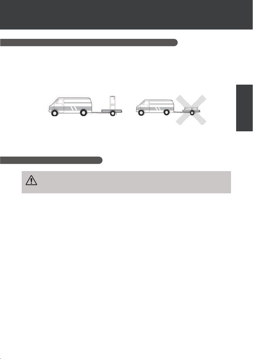
hours.
The device must be stored and transported upright at all times, on a pallet, and in its original
packaging. If the device has been transported in a horizontal position, please wait at least 24
hours prior to connecting it.
1.2 Safety instructions
WARNING: Please read carefully all safety instructions before using the device.
As the instructions noted in this document are essential to your safety, please
respect them carefully.
EN
Installation and maintenance
Only a qualied person may undertake installation, start-up, servicing and repairs, in compliance
with current standards.
Before operating or undertaking any work on the devoce (installation, start-up, use, servicing), the
person responsible must be aware of all the instructions in the heat pump’s installation manual as
well as the technical specications.
Under no circumstances install the equipment close to a source of heat, combustible materials or
a building’s air intake.
If installation is not in a location with restricted access, a heat pump protective grille must be tted.
To avoid severe burns, do not walk on pipework during installation, repairs or maintenance.
To avoid severe burns, prior to any work on the refrigerant system, turn o the heat pump and wait
several minutes before placing temperature and pressure sensors.
Check the refrigerant level when servicing the heat pump.
Check that the high and low pressure switches are correctly connected to the refrigerant system
and that they turn o the electrical circuit if tripped during the equipment’s annual leakage
inspection.
Check that there is no trace of corrosion or oil stains around the refrigerant components.
EN | 1
Page 9

1. GENERAL INFORMATION
When in use
Do not touch the vent during operation due to the risk of serious injury.
Do not leave the heat pump within reach of children due to the risk of injury caused by the heat
exchanger ns.
Never start the equipment if there is no water in the spa or if the circulating pump is stopped.
Check the water ow rate every month and clean the lter if necessary.
When cleaning
1. Switch o the power supply to the device.
2. Close the water inlet and outlet valves.
3. Do not place anything in the openings of the water or air inlets/outlets.
4. Do not spray the appliance with excessive amounts of water.
During repairs
Carry out work on the refrigerant system in accordance with current safety regulations.
Brazing should be performed by a qualied welder.
When replacing a defective refrigerant component, use only parts certied by our technical
department.
When replacing pipework, only copper pipes conforming to Standard NF EN12735-1 may be used
for repairs.
1.3 Water treatment
Poolex heat pumps for spas can be used with all types of water treatment systems.
Nevertheless, it is essential that the treatment system (chlorine, pH, bromine and/or salt chlorina-
tor metering pumps) is installed after the heat pump in the hydraulic circuit.
To avoid any deterioration to the heat pump, the water’s pH must be maintained between
6.8 and 7.8.
2 | EN
Page 10

2. DESCRIPTION
2.1 Operating limits
For the heat pump to operate normally, the ambient air temperature must be between -25°C and
43°C. However, we recommend winterising your spa if the water temperature falls below 10°C.
Your hot tub must be correctly insulated to enable the heat pump to function in an optimal way.
✓ The tub must be insulated.
✓ The piping must be insulated.
✓ The hot tub must be equipped with an insulating cover.
Thanks to the Full Inverter system, the SPA heat pump automatically adapts its power according
to its settings and the external environment. So, when the water temperature rises (this phase can
last up to a week after installation), the SPA heat pump will use all the power available; and once
the target temperature has been reached, the SPA heat pump will reduce its energy consumption.
2.2 Package contents
At reception, please check that your package contains the following:
✓ ICE SPA heat pump
✓ a winter cover
✓ 2 male 1" threaded connections
✓ Remote, waterproof control box (optional): controller, box and cable
✓ 2 control relays
✓ hydraulic hose
✓ hydraulic elbow
EN
2.3 General characteristics
A Poolex heat pump has the following features:
High performance with up to 80% energy savings compared to a conventional heating
system.
Clean, ecient and environmentally friendly R32 refrigerant.
Reliable high output leading brand compressor.
Wide hydrophilic aluminum evaporator for use at low temperatures.
User-friendly intuitive control panel.
Heavy duty shell, anti-UV treated and easy to maintain.
CE certication.
EN | 3
Page 11
2. DESCRIPTION
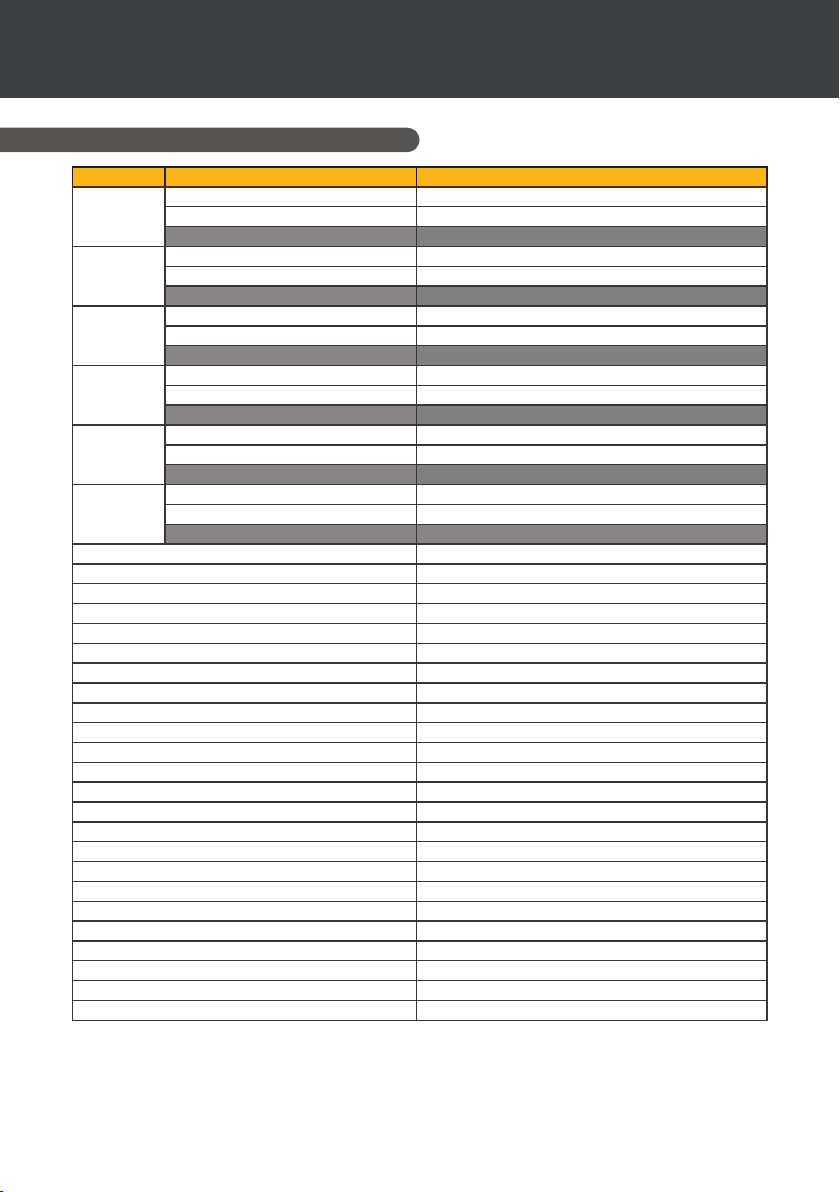
2.4 Technical characteristics
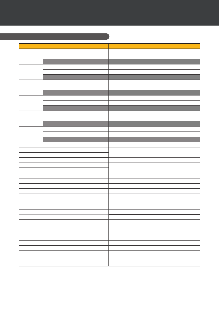
Air
Water
Air
Water
Air
Water
Air
Water
Air
Water
Air
Water
(1)
(1)
(1)
(1)
(1)
-10°C
(1)
Heating power (kW)
26°C
Consumption (kW)
(2)
26°C
COP (Coe. of performance)
Heating power (kW)
15°C
Consumption (kW)
(2)
26°C
COP (Coe. of performance)
Heating power (kW)
15°C
Consumption (kW)
(2)
38°C
COP (Coe. of performance)
Heating power (kW)
26°C
Consumption (kW)
(2)
38°C
COP (Coe. of performance)
Heating power (kW)
Consumption (kW)
(2)
38°C
COP (Coe. of performance)
Cooling capacity (kW)
35°C
Consumption (kW)
(2)
27°C
EER
3.3~7
0.28~1.4
11.9~5
2.3~5.4
0.35~1.1
6.6~4.9
2.8~4.7
0.67~1.3
4.2~3.7
2.8~6
0.29~1.3
9.6~4.5
2.2~3.3
1.2~1.5
1.8~2.1
3.2~3.7
0.87~1.2
3
Power supply Single phase 220-240V ~ 50Hz
Maximum power (kW) 1.7
Maximum current (A) 9
Heating temperature range -25°C ~ 43°C
Cooling temperature range 5 °C ~ 43 °C
Automatic temperature range -25°C ~ 43°C
Unit dimensions L x W x H (mm) 705 x 490 x 505
Unit weight (kg) 43
Sound pressure level at 1m (dBA) < 48
Sound pressure level at 4m (dBA) < 36
Sound pressure level at 10m (dBA)
(3)
< 28
Hydraulic connections (mm) 1" female
Heat exchanger Titanium heating coil
Water ow rate (m³/h) 3.0
Compressor brand GMCC
Compressor type Rotary
Refrigerant R32
Refrigerant volume (g) 650
Minimum pressure (MPa) 0.1
Maximum pressure (MPa) 4.3
Protection rating IPX4
Load loss (kPa) 3.3
Control panel Digital display
Operating modes Heating/Cooling/Auto
The technical specicaons of our heat pumps are provided for informaon purposes only. We reserve the
right to make changes without prior noce.
1
Ambient air temperature
2
Initial water temperature
3
Noise level at a distance of 10 m in accordance with international standards EN ISO 3741 and EN ISO 354
4 | EN
Page 12
2. DESCRIPTION
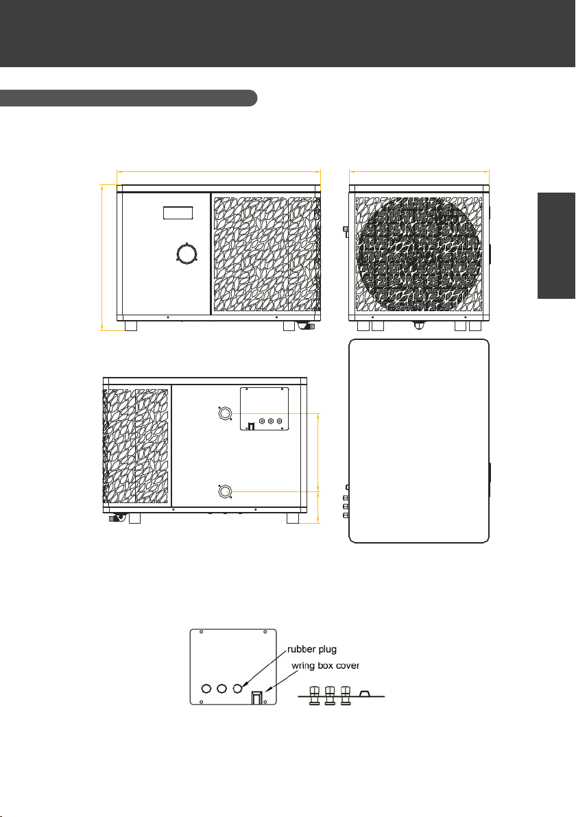
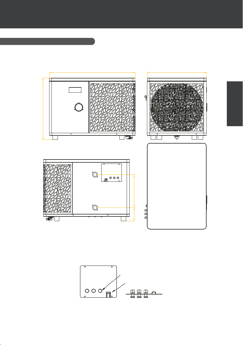
2.5 Product dimensions
Dimensions in mm
705 485
505
270
110
Note: When the electric heating, water pump, and wire control are not fully connected, please use
'rubber plug' to avoid damage due to moisture.
EN
EN | 5
Page 13
2. DESCRIPTION
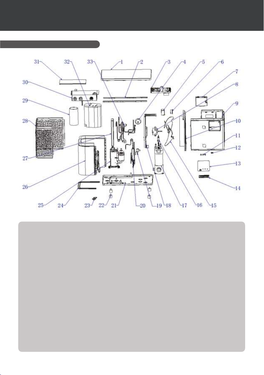
2.6 Exploded view
1. Top cover
2. Side panel mounting strips
3. Electrical components
4. Pressure gauge
5. Inducer seal box
6. Inductor
7. Display box assembly
8. Fan motor
9. Front panel assembly
10. Central bulkhead assembly
11. Cable gland
12. Crimping tool
13. Terminal block cover
14. Terminal block
15. Fan
16. Water ow switch
17. Titanium heat exchanger
6 | EN
18. Motor support component
19. Electronic expansion valve
20. Flash evaporator
21. Chassis components
22. Anti-vibration feet
23. Drain elbow
24. Chassis heating belt
25. Compressor
26. Evaporator components
27. Electrical box support
28. Rear side panel components
29. Sound insulation lining 1
30. Control box
31. Control box cover
32. Sound insulation lining 2
33. 4-way valve
Page 14
3. INSTALLATION
To install the heat pump the hydraulic circuit and the power need to be connected.
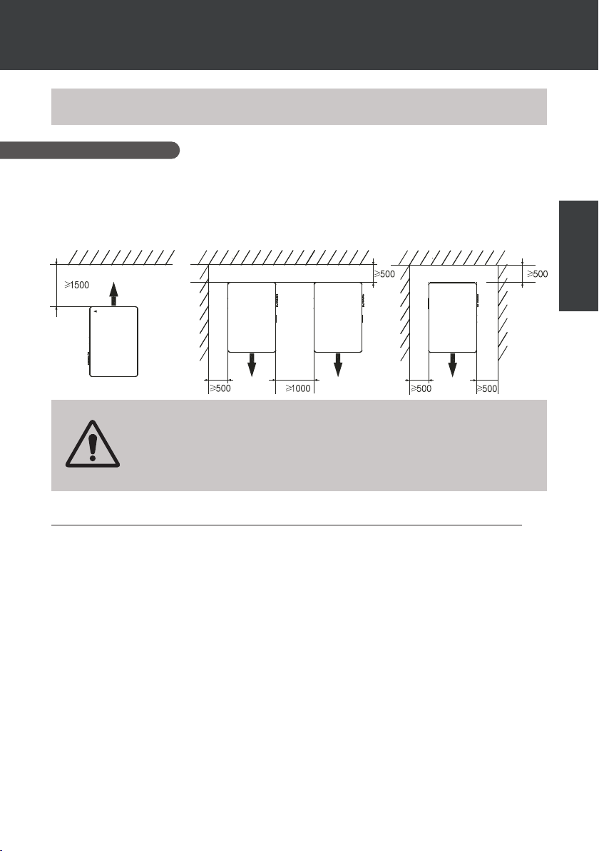
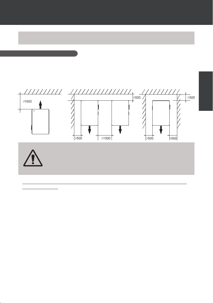
3.1 Location
Standard NF C 15-100 recommends installing the heat pump at least 2.5 meters from the spa.
However, thanks to the dierential circuit breaker, you can also choose to install it closer: Leave at
least 1.50 m in front of the heat pump and 50 cm of empty space to the sides and rear of the heat
pump.
Do not place anything within 1.5m of the front of the heat pump.
Do not place any obstacles on top or in front of the device!
Do not use the heat pump as a step to access the spa.
Do not step on the heat pump.
Dimensions in mm
EN
Please respect the following rules when choosing the heat pump’s installation location
1. The location must be easily accessible for optimal operation and maintenance.
2. The device must be installed on the ground, ideally on a level concrete slab. Ensure that
the ground is suciently stable and it can support the weight of the device.
3. Check that there is enough air ow, that the air exhaust is not directed towards the
windows of neighbouring buildings, and that exhaust air cannot return to the intake. In
addition, ensure that there is enough space around the device to perform servicing and
maintenance.
4. The device must not be installed in locations susceptible of being exposed to oil, amma-
ble gas, corrosive agents, sulphur compounds, or near high frequency devices.
5. Do not install the device near to roads or footpaths to avoid mud splattering.
6. To avoid disturbing neighbours, make sure to install the device facing away from areas
sensitive to noise.
7. Keep out of the reach of children insofar as possible.
EN | 7
Page 15
3. INSTALLATION
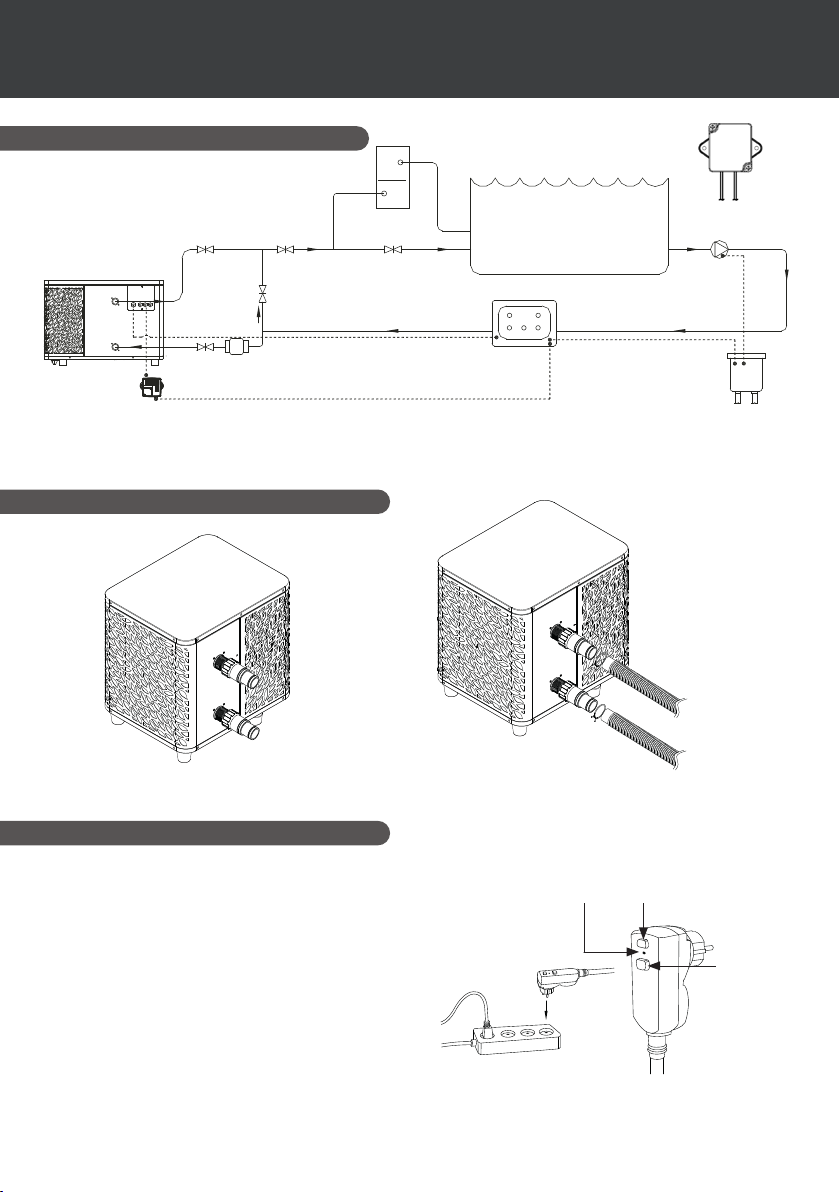
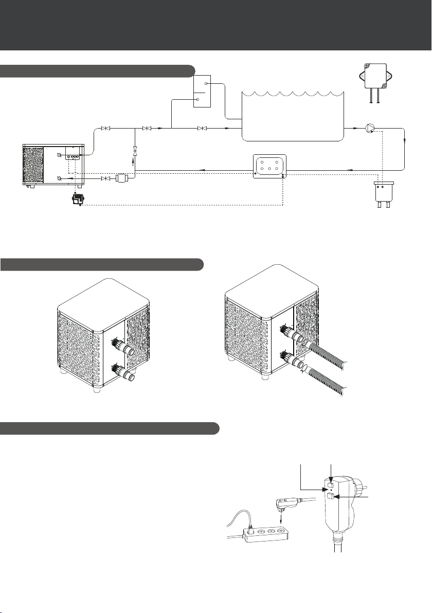
3.2 Installation diagram
Slice Valve
bypass Valve
SPA ICE 70
Outlet
Inlet
In Grid
Slice Valve
Slice Valve
Flow Control Valve
Ozone
UV
Slice Valve
SPA Swimming
pool
SPA Control System
With Electric Heater
*
Water pump
Main
Power
The lter located upstream of the heat pump must be regularly cleared so that the water in the
system is clean, thus avoiding the operational problems associated with dirt or clogging in the lter.
* If the relay is installed outdoor, please install it with the wire outlet side facing down.
3.3 Hydraulic connection
TO THE SPA
Step 1
Screw the connectors for heat pump
3.4 Electrical connection
Pump's power plug integrates a 10mA dierential
circuit breaker.
Regularly test the correct operation. In the event
of successive triggering or doubts contact the
after-sales service.
Before plugging in your heat pump, please
ensure the electrical socket is well protected,
properly grounded and protected from rain as
well as water projections.
Press the RESET button to start the heat pump.
The power indicator lights up in red: the heat
pump is on.
8 | EN
FROM THE SPA
Step 2
Connect the water inlet and outlet
TestPower indicator
Reset
Page 16

3. INSTALLATION
3.5 Operation
Use conditions
For the heat pump to operate normally, the ambient air temperature must be between -25°C
and 43°C.
Advance notice
Prior to starting the heat pump, please:
✓ Check that the equipment is secure and stable.
✓ Check that the gauge indicates a pressure greater than 80 psi.
✓ Check that the electrical wiring is properly connected to the terminals.
✓ Check the earthing connections.
✓ Check that the hydraulic connections are tight and that there is no leakage of water.
✓ Check that the water is circulating correctly in the heat pump and that the ow rate is
adequate
✓ Remove any object that is not required around the equipment and all tools.
Operation
1. Connect the power supply to the device.
2. Start the ltration pump.
3. Activate the device’s electrical supply protection (dierential switch situated on the power
cable).
4. Start the heat pump.
5. Select the desired temperature using one of the modes appearing on the control panel.
6. The heat pump’s compressor will start shortly after.
And you just need to wait for the target temperature to be reached.
EN
WARNING: Under normal conditions, a suitable heat pump can heat up the
tub water by 1°C to 2°C per hour. It is therefore normal that you do not feel any
dierence in temperature at the outlet level when the heat pump is on.
A heated tub must be covered and insulated to avoir any heat loss.
Good to know: restart after power failure
After a power failure or a usual interruption, turn the power back on, the system is on sleep mode.
Restart the dierential plus and switch on the heat pump.
EN | 9
Page 17
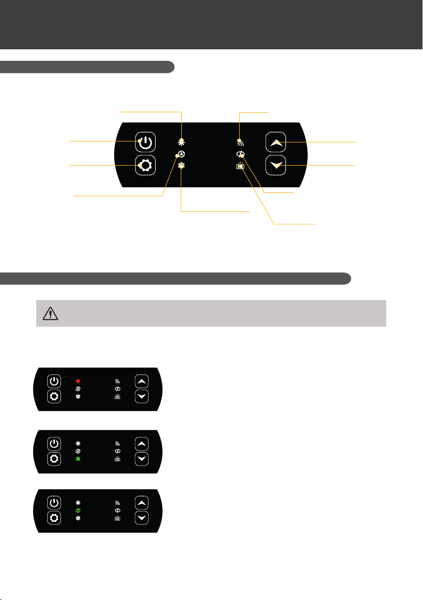
OF CONTROL PANEL
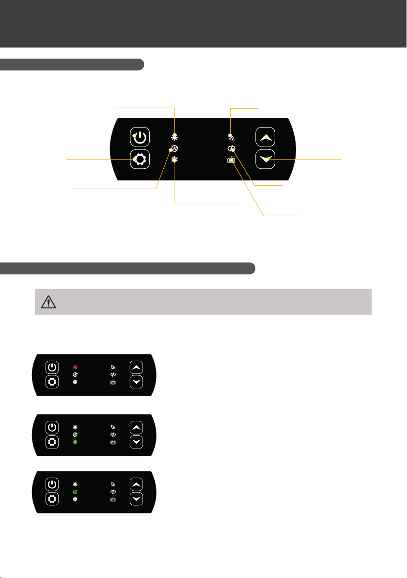
4.1 Control panel
4. USE
"ON/OFF” button
“Mode” button
Automatic mode
Heating mode
Cooling
mode
WiFi indicator
“High” button
“Low” button
Circulation pump
indicator
Heater pilot indicator (RECH
indicator)
4.2 Heating / Cooling / Automatic mode
Before use, ensure that the ltration pump is working and that water is circulating
through the heat pump.
Prior to setting your required temperature, you must rst select an operating mode for your
remote.
Heating mode
Select the heating mode if you want to heat up the tub
water with the heat pump.
10 | EN
Cooling mode
Select the cooling mode if you want to heat up the tub
water with the heat pump.
Automatic mode
Select the automatic mode if you want to let the heat
pump switch to the correct mode in a smart way
according to the target temperature.
Page 18
4. USE
OF CONTROL PANEL
4.3 Functions overview
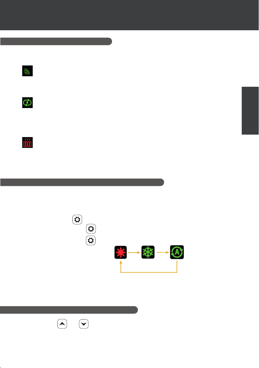
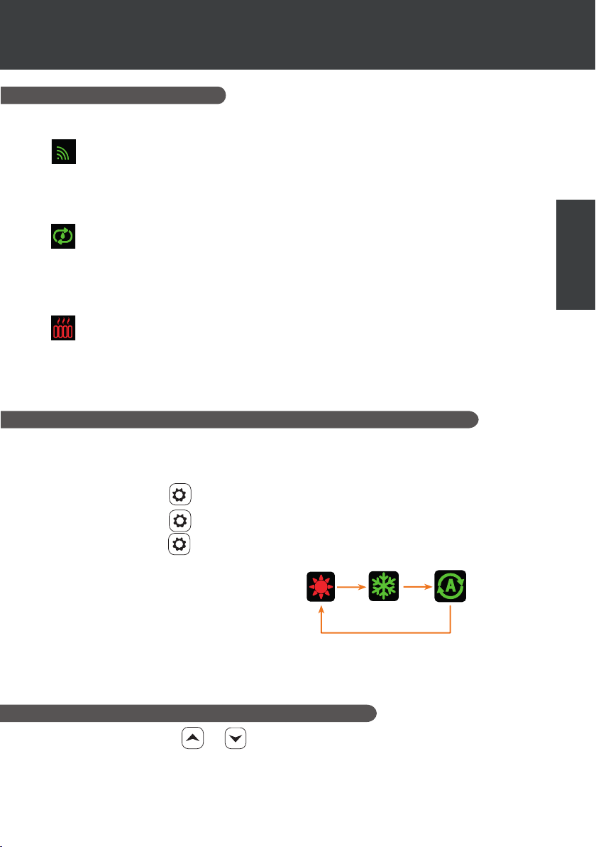
The indicators to the right of the control panel indicate the heat pump’s other functions.
WiFi indicator
Indicates your Wi connection status.
Flashes during pairing (see paragraph "4.7 Wi connection"). It remains on when a
connection is active. The rst time it is switched on, the Wi LED ashes rapidly.
Circulation pump indicator
Lights up when the circulation pump is active:
1. Disable mode: o,
2. Automatic mode: always bright when closed, o when disconnected.
3. Manual mode : ashes when closed, o when disconnected.
Heater pilot indicator
The RECH light is on when the heater is active:
1. Disable mode: o,
2. Automatic mode: always bright when closed, o when disconnected.
3. Manual mode : ashes when closed, o when disconnected.
4.4 Heat pump operating mode selector
EN
By default, the heat pump is in heating mode.
To change the mode of use, when the heat pump is ON:
• Press the button
• Press the button again , the heat pump will then switch to automatic.
• Press the button again , the heat pump will then switch heating.
The dierent modes thus form a cycle:
Good to know:
The heat pump can take several minutes to change operating mode in order to preserve the
refrigerant uid.
The maximum set temperature is 40°C.
, the heat pump will then switch to cooling.
4.5 Set temperature adjustment
Use the arrows and to change the set temperature. The heating setting range is
15-40°C (default 38°C). The refrigeration setting range is 4-35°C (default 32°C). The automatic
setting range is 4-40°C (default 35°C).
EN | 11
Page 19
4. USE
OF CONTROL PANEL
4.6 Locking and unlocking
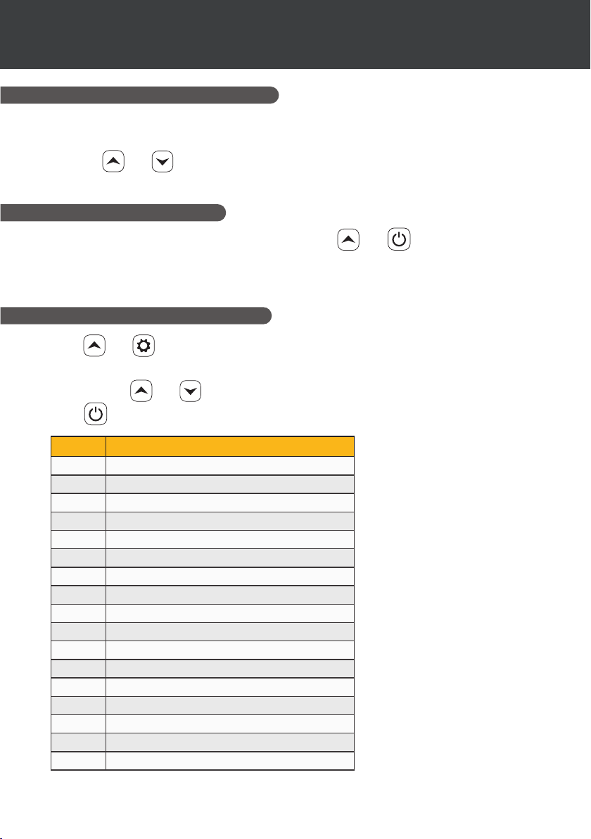
In the main interface, if no key is pressed for 30s, the control panel is locked automatically. When
the screen is locked, it displays "LOC".
Press the
the device unlocks, it emits a long beep.
4.7 Wifi connection
When the heat pump is switched o, press for 5 seconds.
WiFi logo will ash.
See section "7. Use via the mobile application", for more details on the wi pairing procedure.
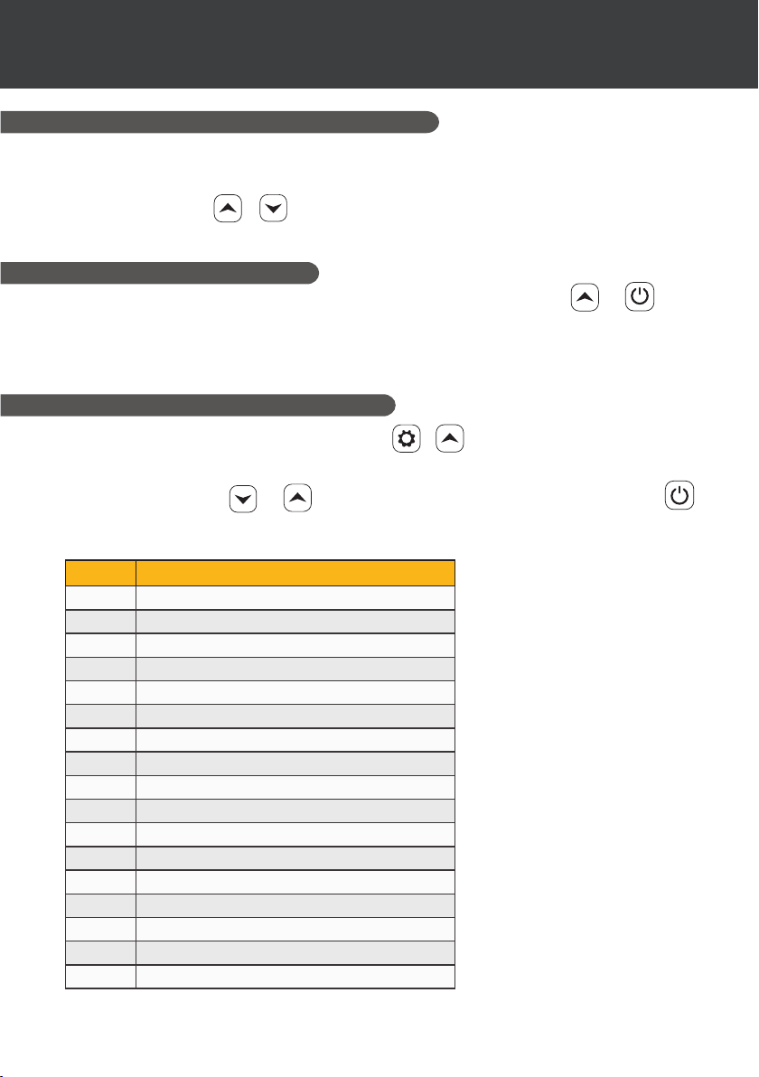
4.8 Viewing status values
and simultaneously for 3 seconds to lock and unlock the control panel. When
and to start WiFi pairing. The
Press
and for 3 seconds to check the status of your heat pump.
The parameter code appears and the value is displayed after 3 seconds.
Use the arrows
and to navigate between the dierent parameters.
Press to return to the main interface.
Code Designation
01
02
03
04
05
06
07
A1
A2
A3
A4
A5
E1
E2
E3
E4
E5
External ambient temperature (°C)
Coil temperature (°C)
Compressor discharge temperature (°C)
Compressor return air temperature (°C)
Inlet water temperature (°C)
Outlet water temperature (°C)
(reserved)
Compressor operating frequency
Fan speed
Electronic expansion valve opening
(reserved)
(reserved)
Historical fault 1 (earlier fault)
Historical fault 2
Historical fault 3
Historical fault 4
Historical fault 5 (recent fault)
12 | EN
Page 20
4. USE
OF CONTROL PANEL
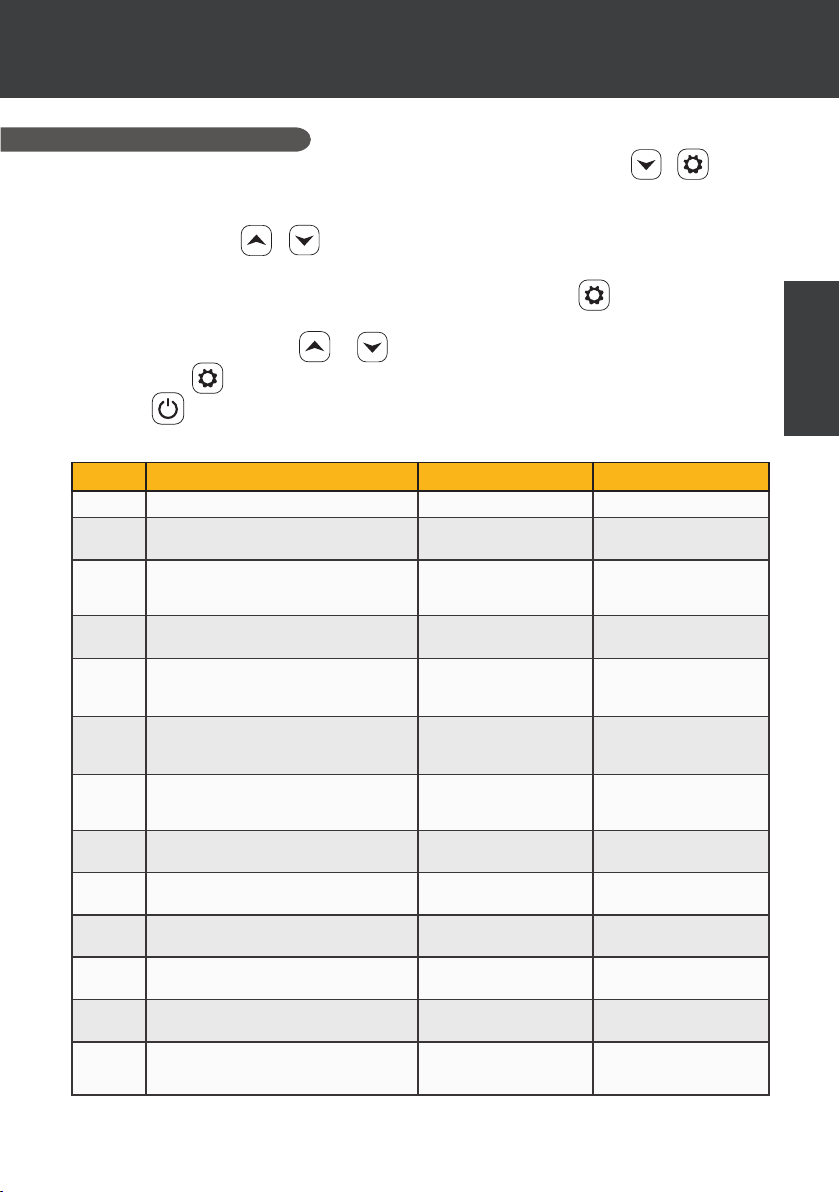
4.9 Setting
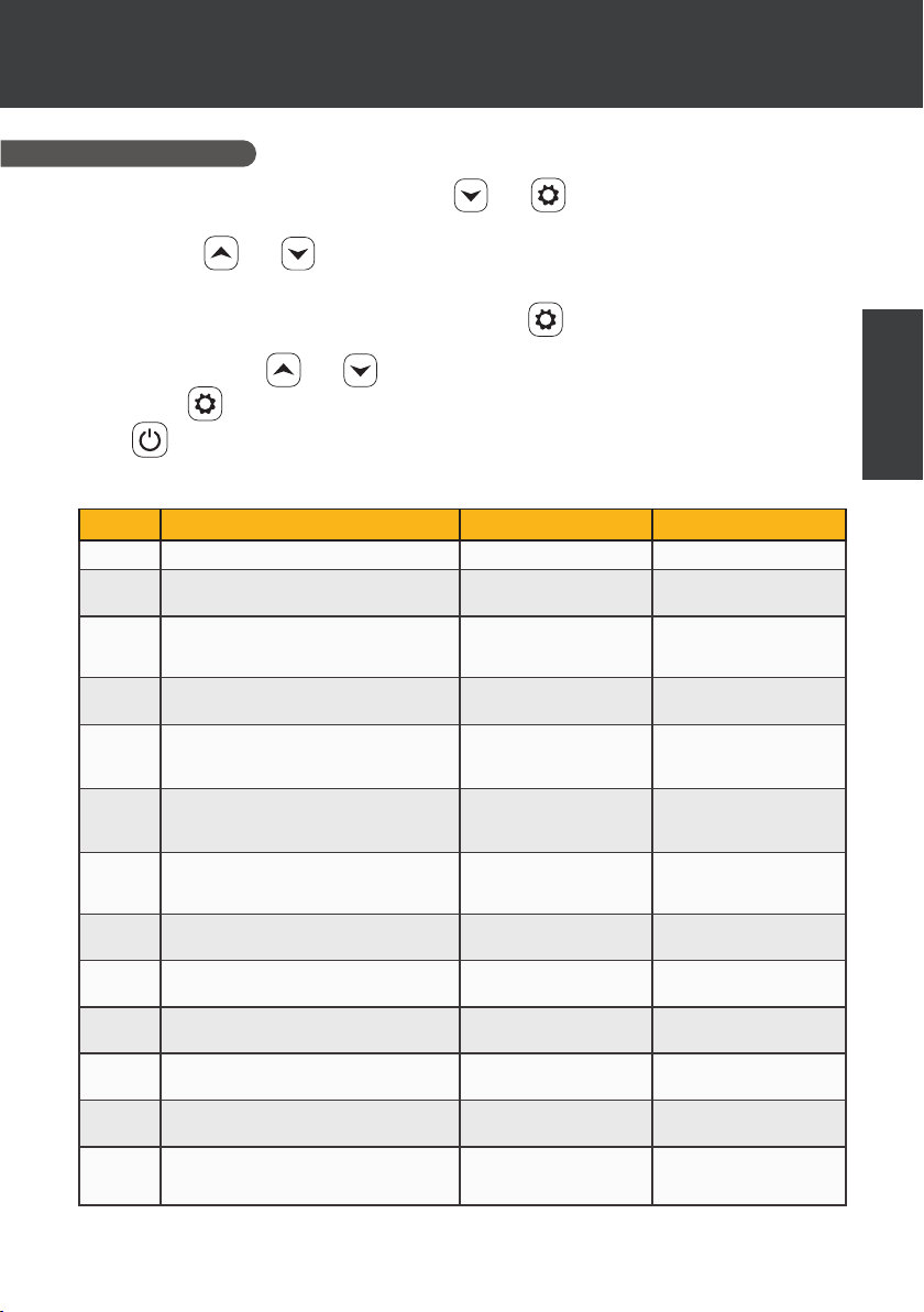
When the heat pump is o, press for 3 seconds. and to access the settings interface.
The parameter code appears and the value is displayed after 3 seconds.
Use the arrows and to navigate between the dierent parameters.
To change a parameter:
1. Display the parameter to be changed, then press .
The parameter value starts ashing.
2. Use the arrows and to change its value.
3. Press to conrm the input value.
Press to return to the main interface.
List of user parameters
Code Designation Range of values Default value
C1
C3
C4
C5
C6
C7
C8
C9
C10
C11
C12
C13
C14
Power-down memory mode 1:On ; 0:Off 1 / on
Refrigeration inlet and outlet water
temperature compensation settings
Heater relay function selection 0: Disabled
Ambient temperature judgment
value for starting heater
Water temperature difference
judgment value for restarting
heater
Water temperature difference
judgment value for restarting
heater in manual mode
Circulation pump relay function
selection
Water temperature interval for
temperature checks
Water temperature difference for
restart in heating mode
Water temperature difference when
stopped in heating mode
Water temperature difference for
restart in cooling mode
Water temperature difference when
stopped in cooling mode
Dry contact function selection 0: Disabled
-4°C~0°C 0°C
1: Automatic
2: Manual
0: Disabled
-25°C~20°C 5°C
1°C~5°C 5°C
1°C~5°C 2°C
0: Disabled
1: Automatic
2: Manual
30~90min 60min
0°C~10°C 2°C
0°C~10°C 2°C
0°C~10°C 2°C
0°C~10°C 2°C
1: DOMOSWITCH
mode
0: Disabled
1 / on
EN
EN | 13
Page 21

4. USE
OF CONTROL PANEL
4.10 Forced defrost
The heat pump must be set to 40°C for this procedure to work.
Set the heat pump to 40°C in heating mode, then use the arrows and to force defrosting:
> > > > > , 6 strides alternating the two arrows, starting with the top one.
Note: If the heat pump is in cooling mode and the temperature is set to 20°C, this procedure
initiates refrigerant recovery.
4.11 Error display
When a system error occurs, the display panel shows the error code.
When several errors occur, each error code is displayed for 8 seconds, cyclically, and the error
code does not ash.
Refer to the table in section "7.3 Breakdown and faults" for more details on errors.
14 | EN
Page 22
5. USE
OF WIRE CONTROLLER
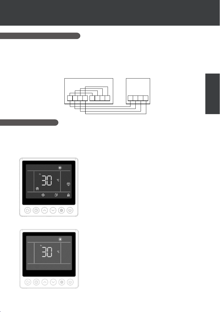
5.1 Installation
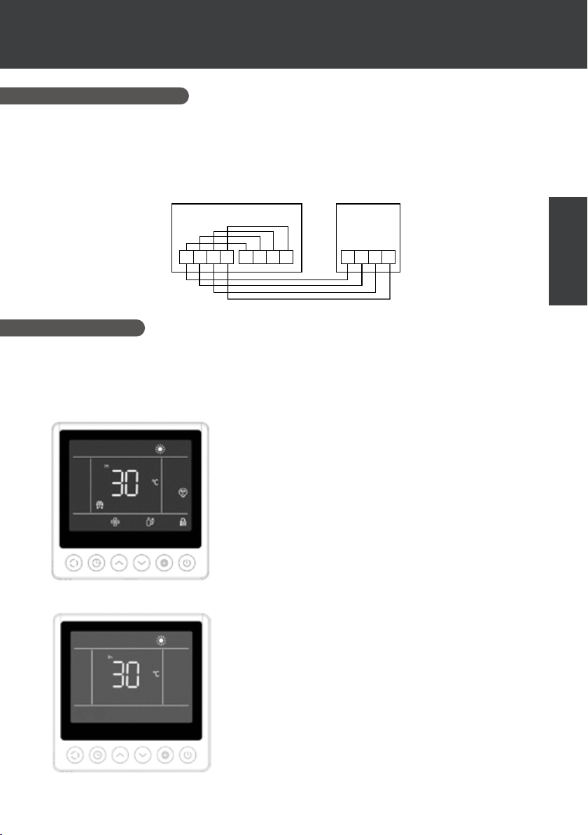
The remote control panel or wire controller is an option that allows you to control your heat pump
from a remote location.
To optimise the readability of the screen and its durability, place it away from direct sunlight, rain
and splashing water (IPX5 protection rating).
Follow the diagram opposite to connect the remote control panel.
12V BG
Motherboard
B
A
12V
A
G
Controller
12V BG
A
5.2 Start
Initial interface
When the wire controller is switched on, all the patterns are displayed on the LCD screen. After 5
seconds, the buzzer sounds to enter the normal interface.
Start-up interface
The start-up interface displays the default inlet water temperature
(the set temperature ashes for 5 seconds when the temperature
is set), the current mode, the start-up icon and the actual functions
(programmed start, defrost, antifreeze status, fan status, compressor status, child lock status).
Example of display:
1. The current inlet water temperature is 30°C.
2. Start, heating mode and child lock
3. Fan motor and compressor are running
4. Enter defrost state
Shutdown interface
EN
The shutdown interface displays the inlet water temperature, the
current mode and the current functions (programmed shutdown,
child lock).
Example of display:
1. The current inlet water temperature is 30°C.
2. Stop and heat mode
EN | 15
Page 23
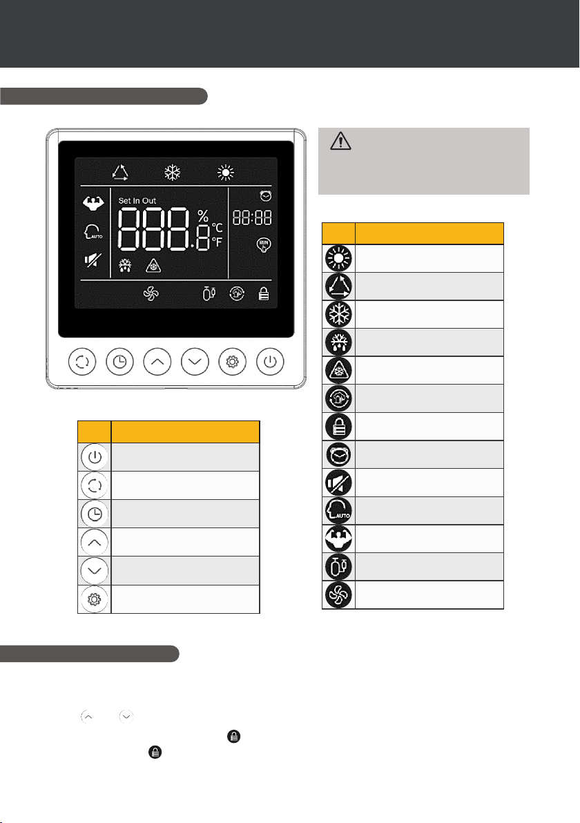
OF WIRE CONTROLLER
5.3 Control panel
5. USE
Before use, ensure that the
ltration pump is working and that
water is circulating through the heat
pump.
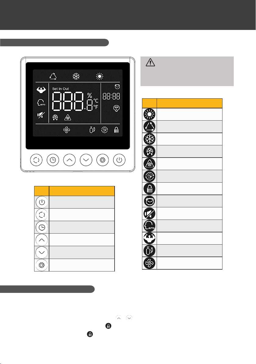
Fonction
Heating mode
Automatic mode
Cooling mode
Defrost
Frost protection
Circulation pump
Fonction
ON/OFF button
Mode selection button
Clock button
UP button
DOWN button
Parameter
Lock icon
Time programming
Silent mode
Smart mode
Boost mode
Compressor ON
Fan ON
5.4 Unlocking
If the unit goes 30 seconds without any input operation, the controller screen enters a sleep state.
However, the screen must be locked manually (child lock).
Press and for 5 seconds to lock or unlock the screen.
When the screen is locked, the icon
"beep" and the icon ashes.
16 | EN
lights up, and if a button is pressed, the device emits a
Page 24
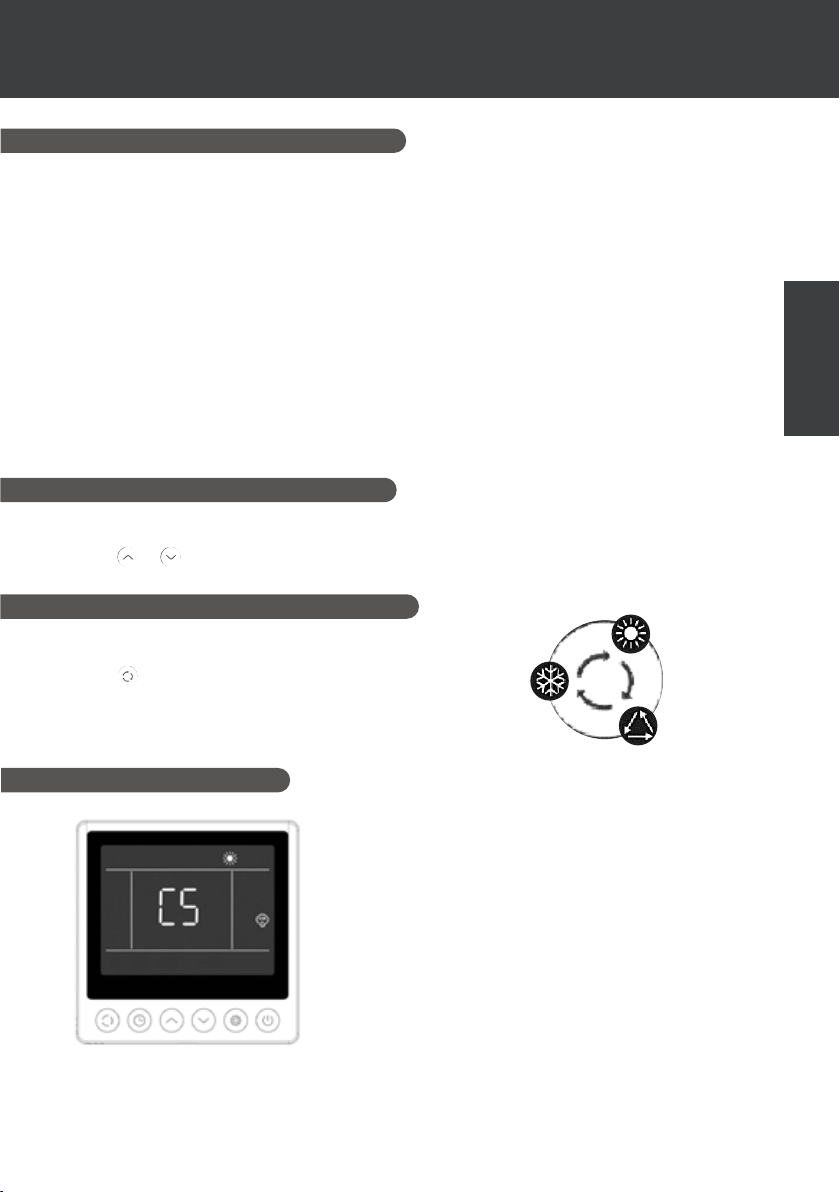
5. USE
OF WIRE CONTROLLER
5.5 Sound and light settings
Audible warning
Each time it is pressed, the buzzer emits a short beep. The user can deactivate the buzzer by
setting parameter P1 to 0. See "5.10 User parameters".
Backlighting
Set parameter P2 on the remote control panel to 1 to activate the backlight or to 0 to deactivate
the backlight. See "5.11 User settings".
By default, the backlight is at its brightest when the controller is in use.
After 15 seconds without pressing, the controller switches to half-wake mode and the backlight dims.
After 15s without pressing half-wake, the controller switches to standby mode. By default, the
lighting is at its minimum (15%). Parameter P3 can be used to switch o the screen in standby
mode (setting 2) or to keep the lighting at its maximum (setting 0).
Parameter P4 is used to modify the intensity of the maximum backlighting.
5.6 Setting the temperature
In the main interface, unlock the screen and then :
Press
5.7 Choice of operating mode
or to adjust the value. The "set" icon lights up.
EN
In the main interface, unlock the screen and then :
Press to switch from one mode to the other.
5.8 Error display
When an error occurs, the temperature display area will show the
error code. When there is more than one error, they are displayed
one after the other.
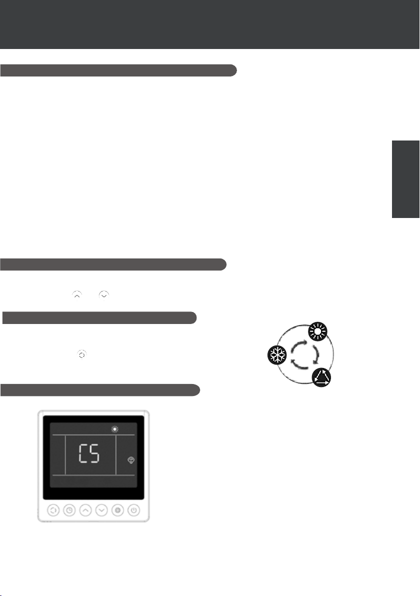
Example of display:
1. Heating is in progress, but error C5 occurs.
Refer to the table in section "8.3 Faults and malfunctions" for
more details on faults.
EN | 17
Page 25
OF WIRE CONTROLLER
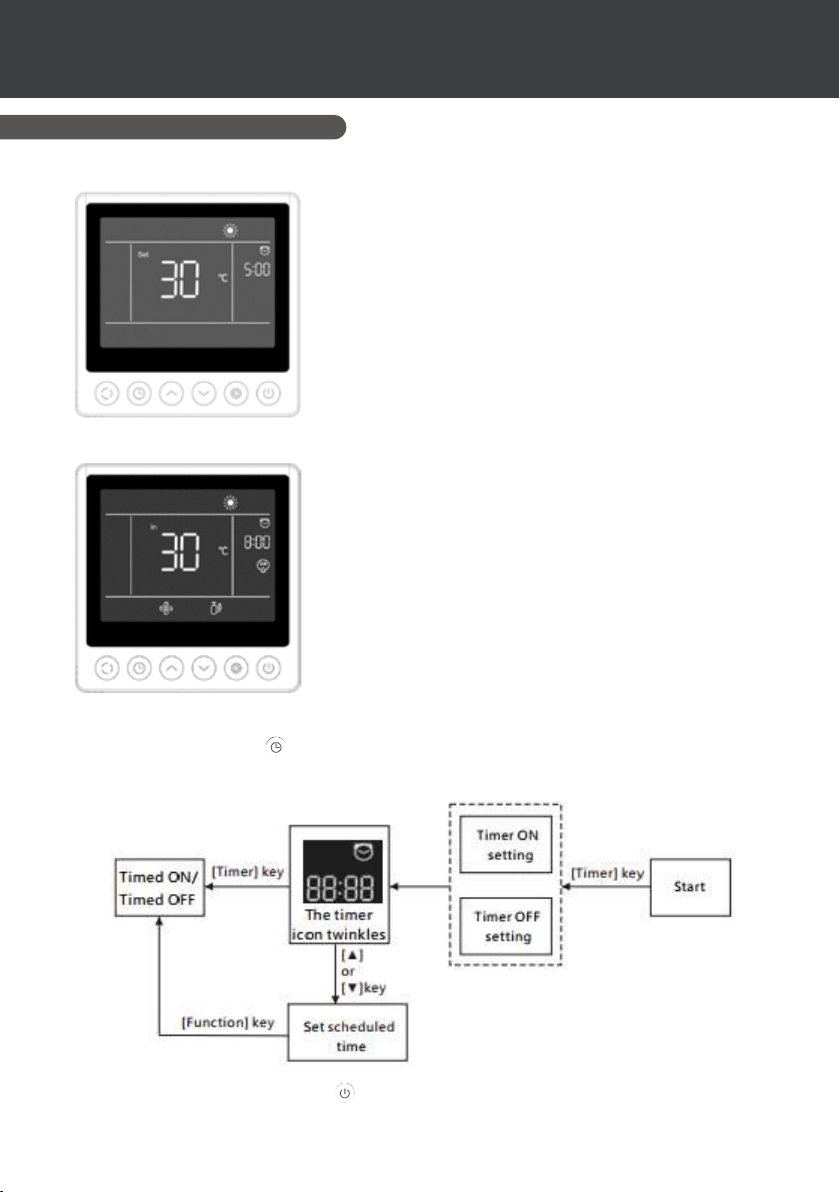
5.9 Time programming
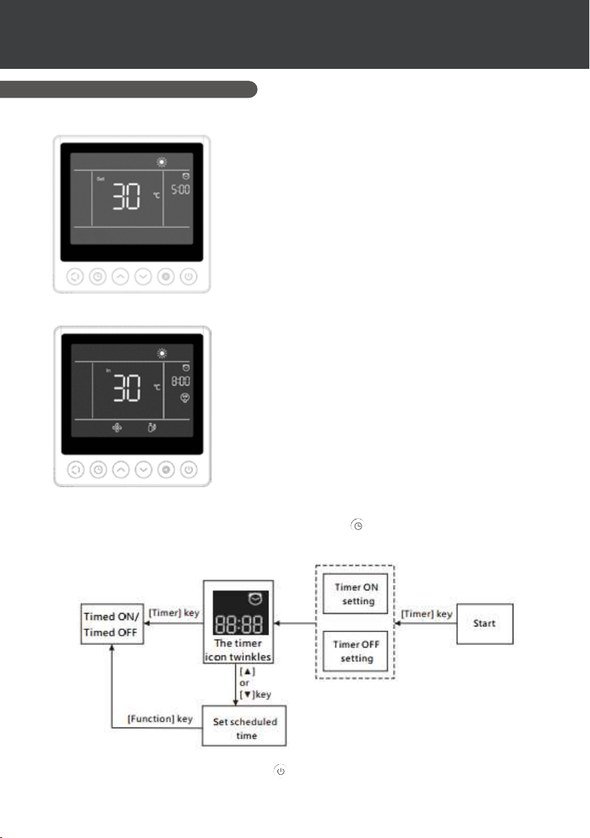
Timer ON interface
Programmed start displays the time and icon, as well as the set
temperature that will be executed after start-up. The other displays are consistent with the shutdown interface.
Example of display:
1. Heating will start in 5 hours.
2. Set the target temperature to 30°C.
Timer OFF interface
The programmed stop displays the time and the icon, and the
other displays conform to the start-up interface.
Example of display:
1. The heating is on and the current inlet water temperature is
30°C.
2. Stop in 8 hours.
3. The fan motor and compressor are running.
5. USE
Procedure
Users can briey press the to set the timer.
The adjustment steps are shown in the gure below:
Cancel the timer by pressing the key .
18 | EN
OR
Page 26
5. USE
OF WIRE CONTROLLER
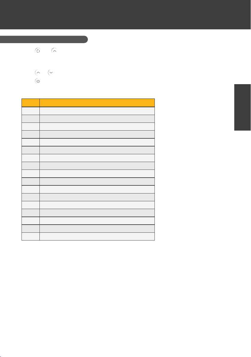
5.10 Status values
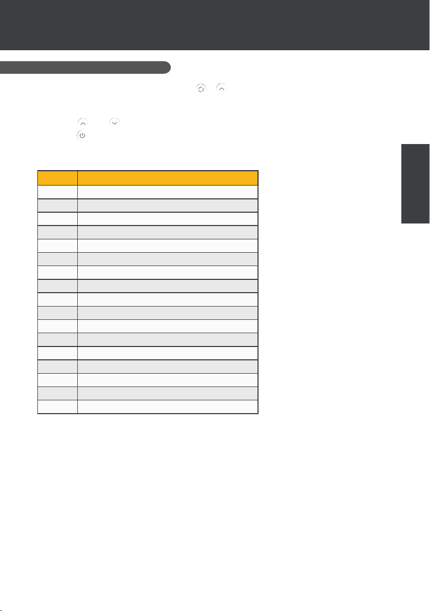
Press and for 5 seconds to view the status values.
In this interface, the time zone displays the code of the parameter to be interrogated and the
temperature zone displays the value of the parameter.
Press or to move up or down the page.
Press to return to the main interface.
Unit status control panel
N° Description
01
External ambient temperature (°C)
02
Coil temperature (°C)
03
Compressor discharge temperature (°C)
04
Compressor return air temperature (°C)
05
Inlet water temperature (°C)
06
Outlet water temperature (°C)
07
(reserved)
A1
Compressor operating frequency
A2
Fan speed
A3
Electronic expansion valve opening
A4
(reserved)
A5
(reserved)
E1
Historical fault 1 (earlier fault)
E2
Historical fault 2
E3
Historical fault 3
E4
Historical fault 4
E5
Historical fault 5 (recent fault)
EN
EN | 19
Page 27
5. USE
OF WIRE CONTROLLER
5.11 User settings
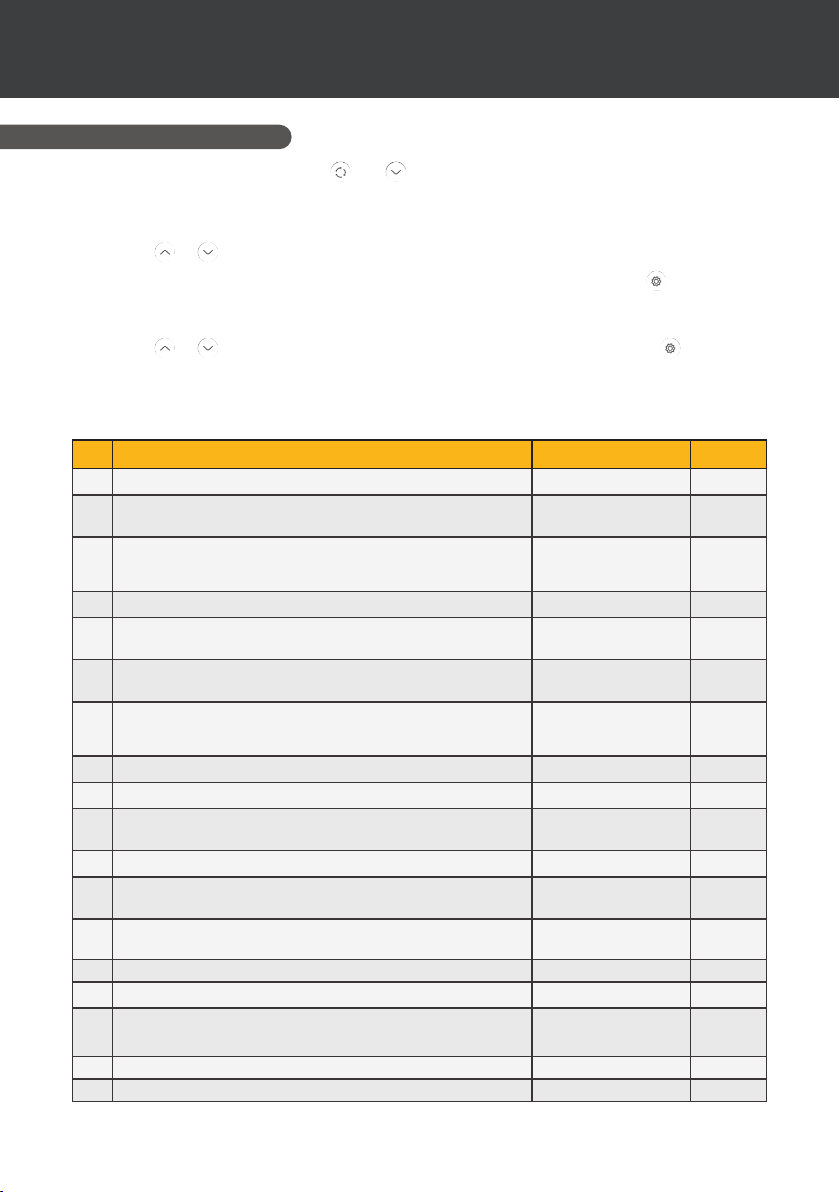
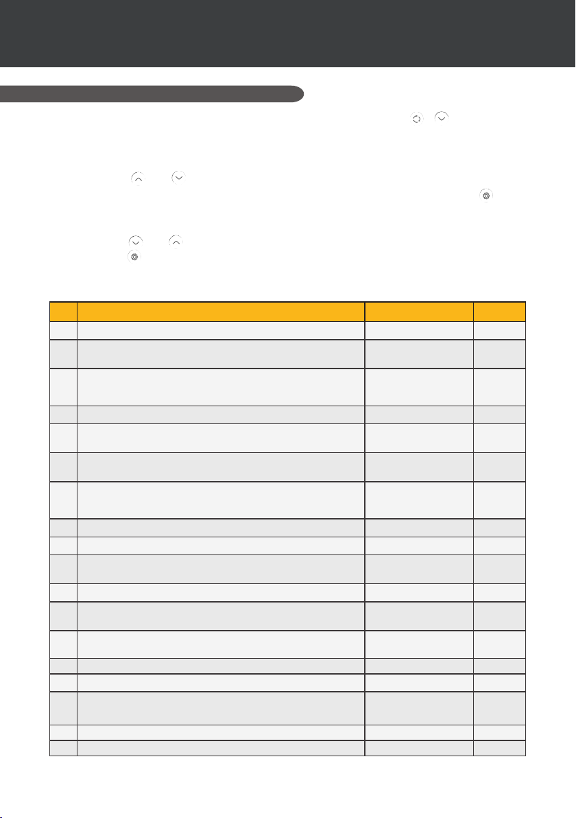
1. From the main interface, press and for 5 seconds to access the user parameters
consultation interface.
In this interface, the time zone displays the code of the parameter to be interrogated and the
temperature zone displays the value of the parameter.
Press or to view each parameter.
2. In the user parameters consultation interface, select a parameter and press to access the
interface for setting this user parameter.
The parameter value (time zone) starts ashing.
3. Press or to change the value of the current user parameter, then press to conrm
the change to the parameter value and return to the parameter consultation status.
List of user settings
N° Description Range of values
Power-down memory mode 1:On ; 0:O 1 / on
C1
Refrigeration inlet and outlet water temperature
C3
compensation settings
Heater relay function selection 0 : O
C4
Ambient temperature judgment value for starting heater -25°C~20°C 5°C
C5
Water temperature difference judgment value for
C6
restarting heater
Water temperature difference judgment value for
C7
restarting heater in manual mode
Circulation pump relay function selection 0 : O
C8
Water temperature interval for temperature checks 30~90min 60min
C9
Water temperature difference for restart in heating mode 0°C~10°C 2°C
C10
Water temperature difference when stopped in heating
C11
mode
Water temperature difference for restart in cooling mode 0°C~10°C 2°C
C12
Water temperature difference when stopped in cooling
C13
mode
Dry contact function selection 0 : O
C14
P1
Audible warning O / On on
P2
Backlighting of the wired controller O / On on
P3
Setting the backlight mode
P4
Maximum brightness setting 30%~100% 100%
P5
Setting the wired controller address 01/02 02
-4°C~0°C 0°C
1: Automatic
2 : Manual
1°C~5°C 5°C
1°C~5°C 2°C
1: Automatic
2 : Manual
0°C~10°C 2°C
0°C~10°C 2°C
1: In.grid mode
0: maximum brightness
1 : max / 50% / 15%
2 : max / 50% / o
D. value
0
0
1 / on
1
20 | EN
Page 28
*
*
6. USE
OF OPTIONAL CONTROL RELAYS
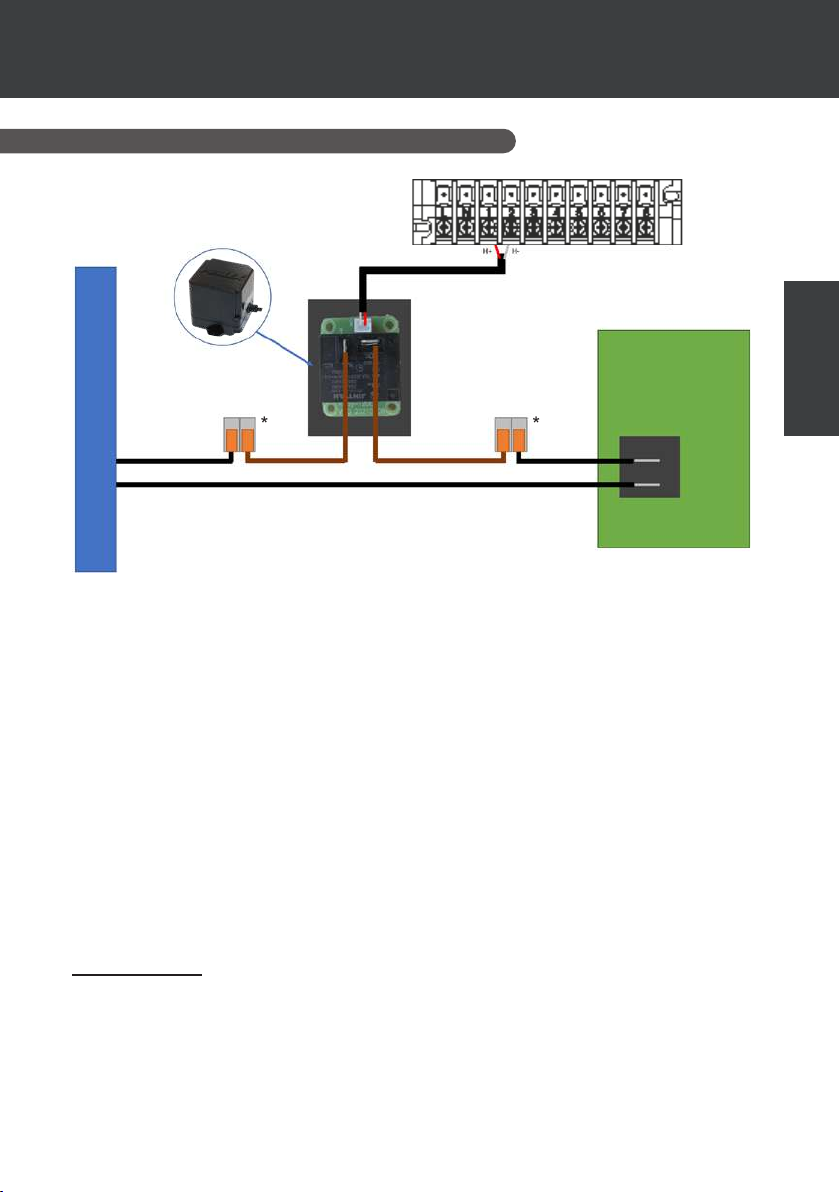
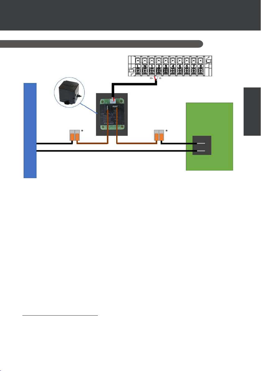
6.1 Using the SPA heater control relay
Poolex Relay
240VAC 30A
125VAC 30A
250VAC 15A cos Ø = 0.4
SPA heater 3kW 230V
The SPA heater driver system consists of a power relay (230V50Hz / 30A) which plugs into
the heater phase wire (between the SPA heater controller output and the heater itself).
This relay is controlled by the heat pump control box either automatically or manually (boost).
As such, for the system to work properly, it is imperative to set the desired temperature of
the SPA water to the maximum on the SPA control screen and to programme the ltration
time. In this way, the actual temperature setting will now be done on the heat pump or via the
smartphone application.
- In automatic spa heater mode: When weather conditions become dicult for the heat pump
(C5 setting: outside temperature below a specied temperature, adjustable from -25 to 20°C)
and the desired bathing temperature is higher than the measured water temperature (C6 setting,
adjustable from 1 to 5°C), the heater control relay is triggered. Thus the heating uses the electric
heater of the SPA in addition to the heat pump in order to reach the desired temperature.
- In manual spa heater mode: Regardless of the weather conditions, as soon as the deviation
between setpoint and measured temperature exceeds the set deviation (C7 setting, adjustable
from 1 to 5°C), the relay is triggered. Thus the heating uses the electric heater of the SPA in
addition to the heat pump in order to reach the desired temperature.
To use this relay:
Setting the C4 setting = 1 to
mode (see
"4.9 Setting" or
Insulate the connectors inside the spa in a
waterproof connection box
( * elements not provided)
activate
control
in automatic mode or C4 = 2 to activate control in manual
"User parameters").
SPA heater
controller
EN
EN | 21
Page 29
*
*
6. USE
OF OPTIONAL CONTROL RELAYS
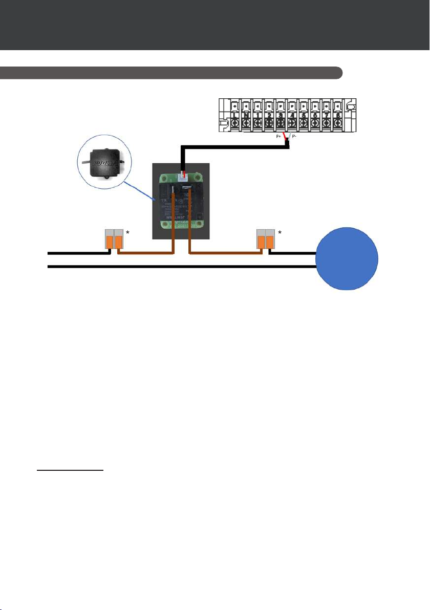
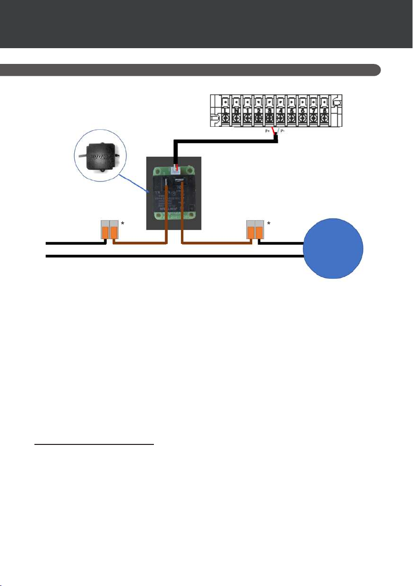
6.2 Using the circulation pump control relay (optional)
Poolex Relay
240VAC 30A
125VAC 30A
250VAC 15A cos Ø = 0.4
L
N
Insulate the connectors inside the spa in a
waterproof connection box
( * elements not provided)
This relay is controlled by the heat pump control box either automatically or manually.
As such, for the system to function correctly, it is imperative to have a circulation pump which
ow ranges of 3 m³/h.
In automatic mode: The relay activates itself every 60 minutes (timing adjustable between 30
and 90 minutes, C9 setting) to control the circulation pump whilst temperature is being veried. If
needed, the controller starts the heat pump to reach the target temperature while the pump relay
remains active up until the target temperature is reached, then will start its verication cycle every
60 minutes (timing adjustable between 30 and 90 minutes, C9 setting).
In manual mode: The pump relay will always be active and the pump will function 24/7.
To use this relay:
Setting the C8 setting = 1 to start the control (see
Adjusting verication time intervals, C9 setting, if necessary (adjustable from 30 to 90 minutes).
"4.9 Setting" or "User parameters")
Circulation
pump
.
22 | EN
Page 30
7. USE
VIA MOBILE APPLICATION
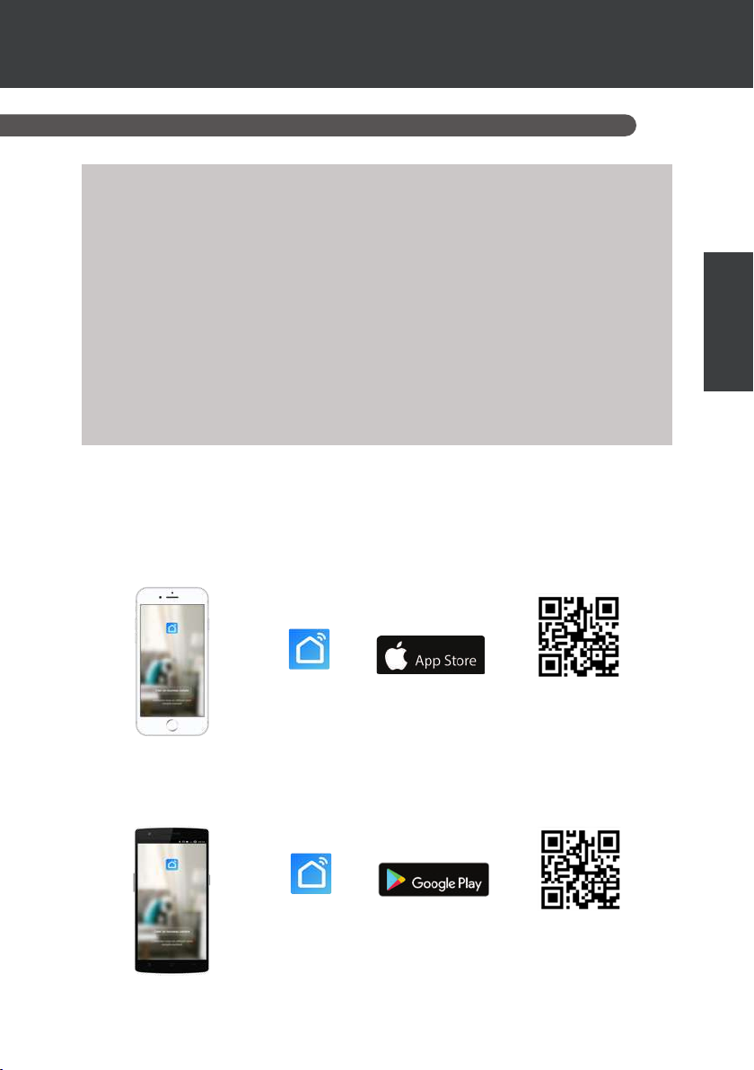
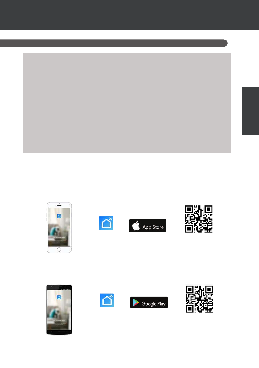
7.1 Downloading & installing the application «Smart Life»
About the Smart Life app:
You’ll need to create a «Smart Life» account to control your heat pump remotely.
The «Smart Life» app lets you control your home appliances from anywhere. You can add
and control multiple devices at once.
- You can share your devices with other Smart Life accounts that you have set up.
- Receive real-time operational alerts.
- Create scenarios with several devices, depending on the app’s weather data (geoloca-
tion required).
For more information, refer to the “Help” section of the “Smart Life” app.
The “Smart Life” app and services are provided by Hangzhou Tuya Technology. The
company Poolstar, owner and distributor of the Poolex brand, cannot be held responsible
for the operation of the "Smart Life" application.
The company Poolstar has no access to your “Smart Life” account.
We're presenting the "Smart Life" application because it's the one we use for our tests, but you
can also choose an equivalent application, such as "Tuya Smart".
iOS:
Scan or search for «Smart Life» in the App Store to download the app:
EN
Download from
Smart Life
Check the compatibility of your phone and the version of your OS
before installing the application.
Android:
Scan or search for «Smart Life» in the play to download the app:
Download from
Smart Life
Check the compatibility of your phone and the version of your OS
before installing the application.
EN | 23
Page 31
7. USE
VIA MOBILE APPLICATION
7.2 Setting up the application
WARNING : Before you begin, make sure you have downloaded the «Smart Life» app,
connected to your local WiFi network, and that your heat pump is electrically powered
and running.
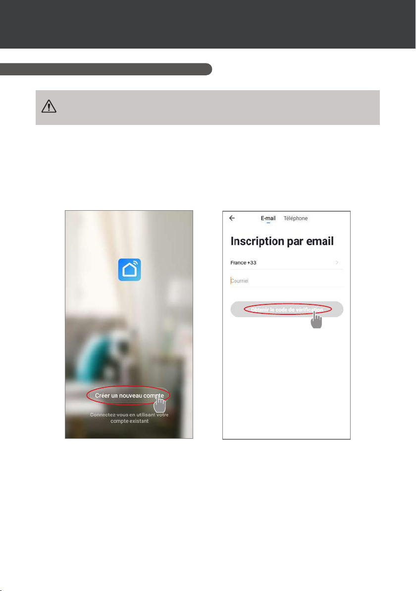
You’ll need to create a «Smart Life» account to control your heat pump remotely. If you already
have a Smart Life account, please log in and go directly to step 3.
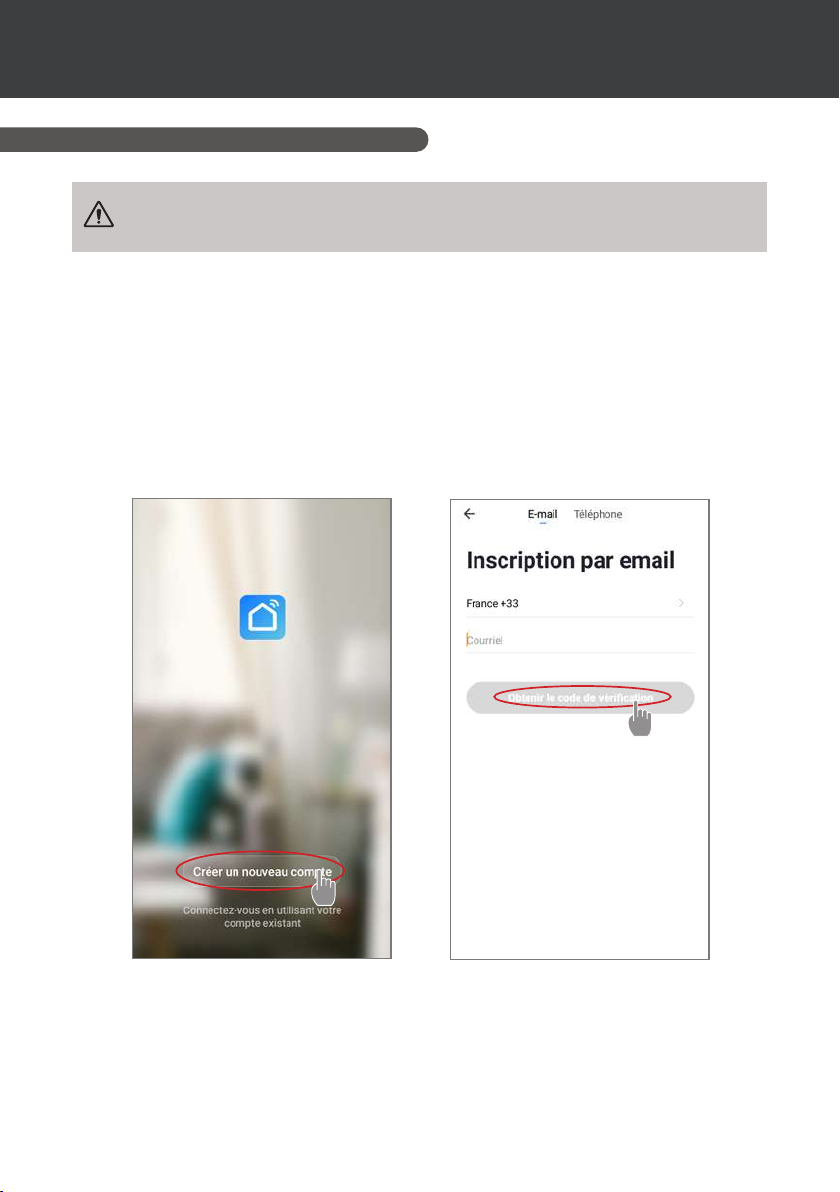
Step 1: Click on «Create new account» and choose to register by «Email» or «Phone,» where a
verication code will be sent to you.
Enter your email address or phone number and click «Send verication code».
Step 2: Enter the verication code received by email or phone to validate your account.
Congratulations, you now belong to the “Smart Life” community.
24 | EN
Page 32
7. USE
VIA MOBILE APPLICATION
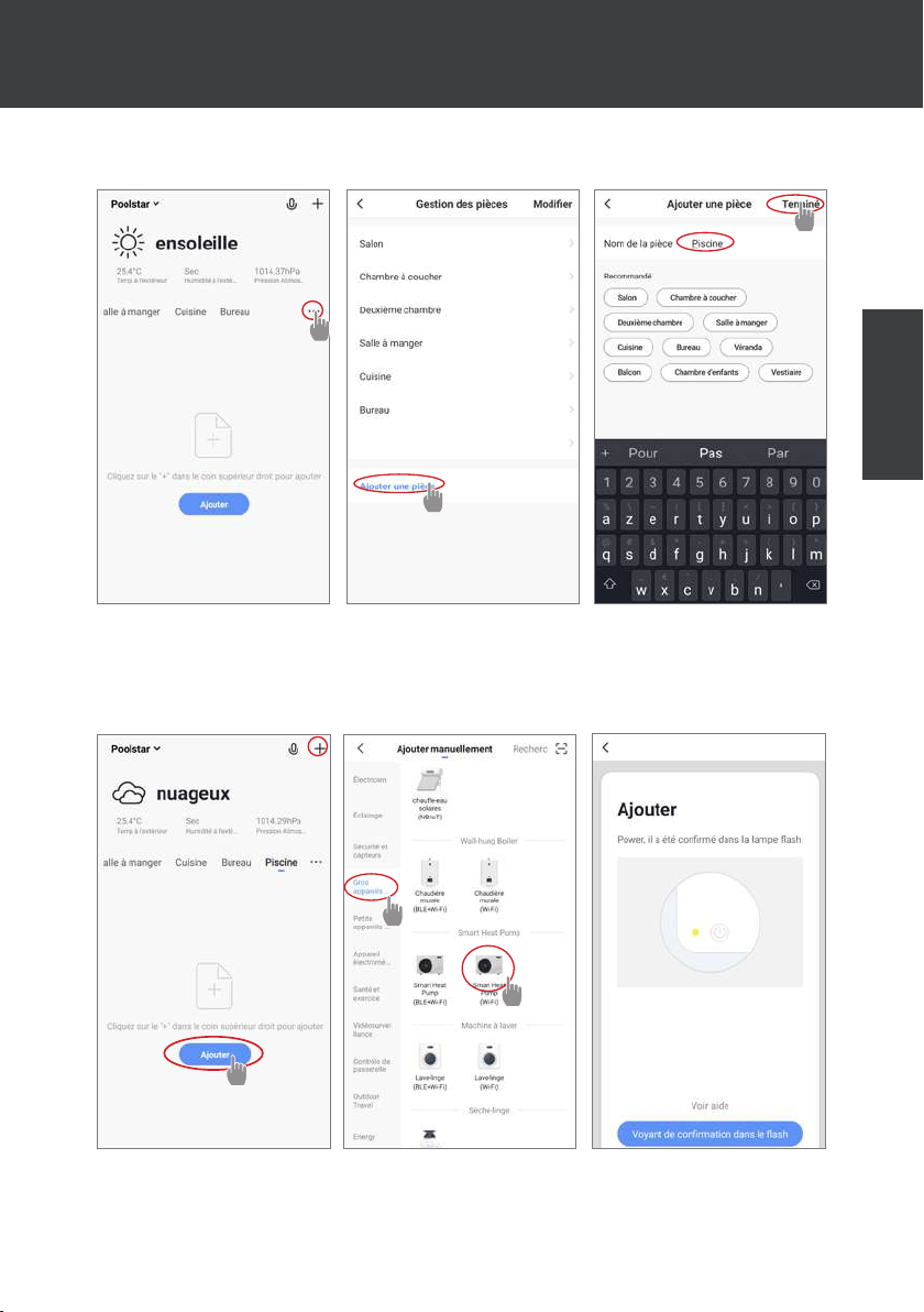
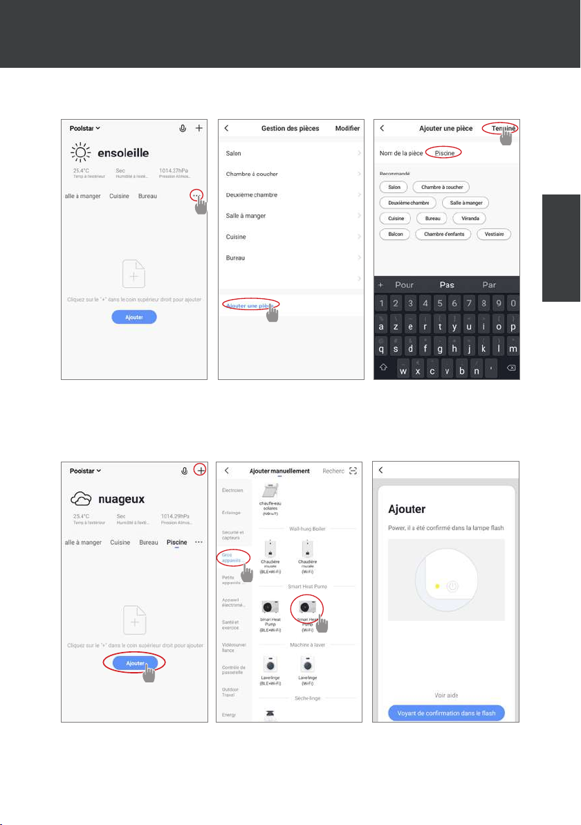
Step 3 (recommended): Add an object by clicking “...” and then “Add Object”. Enter a name
(«Pool» for example), then click “Done”.
Step 4: Now add a device to your “Pool”.
Click “Add” or “+” and then “Large appliances...” followed by “Water heater”.
At this point, leave your smartphone on the “Add” screen and go to the pairing step for
your control box.
EN
EN | 25
Page 33
7. USE
VIA MOBILE APPLICATION
7.3 Pairing the heat pump
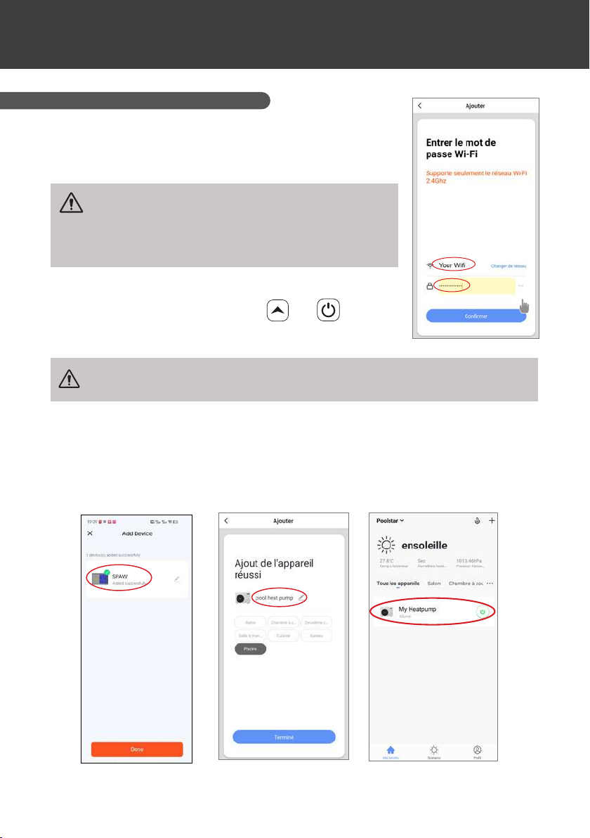
Step 1: Now start the pairing.
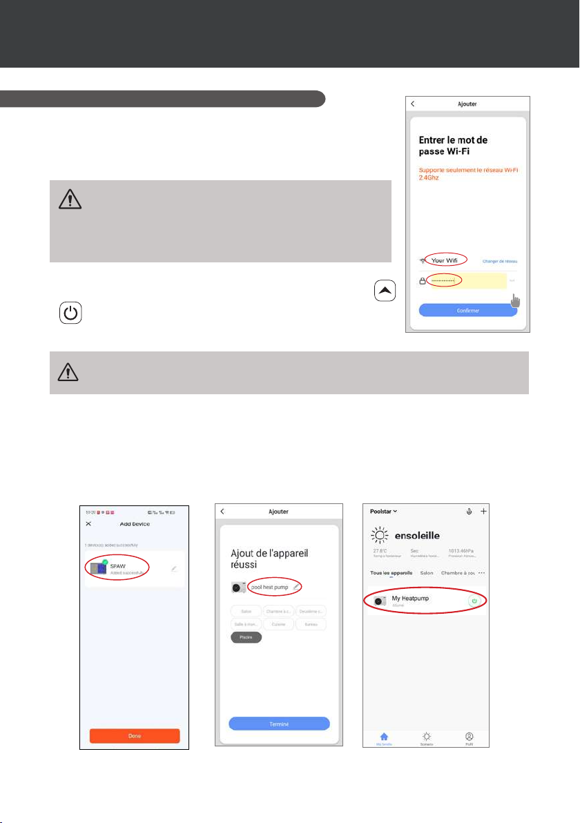
Choose your home WiFi network, enter the WiFi password and press
“Conrm”.
WARNING : The «Smart Life» application only supports
2.4Ghz WiFi networks.
If your WiFi network uses the 5GHz frequency, go to the interface of
your home WiFi network to create a second 2.4GHz WiFi network
(available for most Internet boxes, routers and WiFi access points).
Step 2: Activate the pairing mode on your heat pump.
When the heat pump is switched o, press
seconds to start WiFi pairing. The WiFi logo will ash.
If there is a pairing problem, or if the heat pump is out of range of your wi, you
will need to use a wi amplier or relay (not supplied).
The pairing is successful, you can rename your Poolex heat pump then press “Done”.
and for 5
Congratulations, your heat pump can now be controlled from your smartphone.
26 | EN
Page 34
7. USE
VIA MOBILE APPLICATION
7.4 Controlling
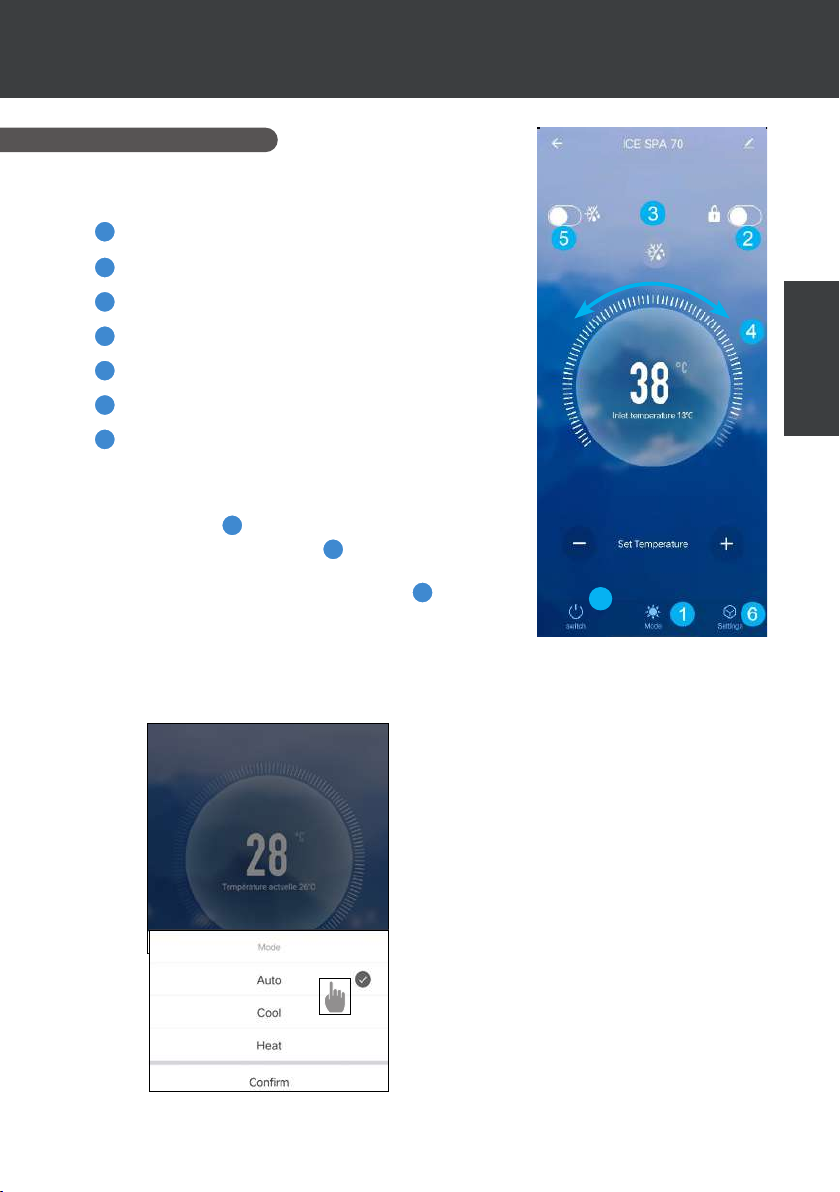
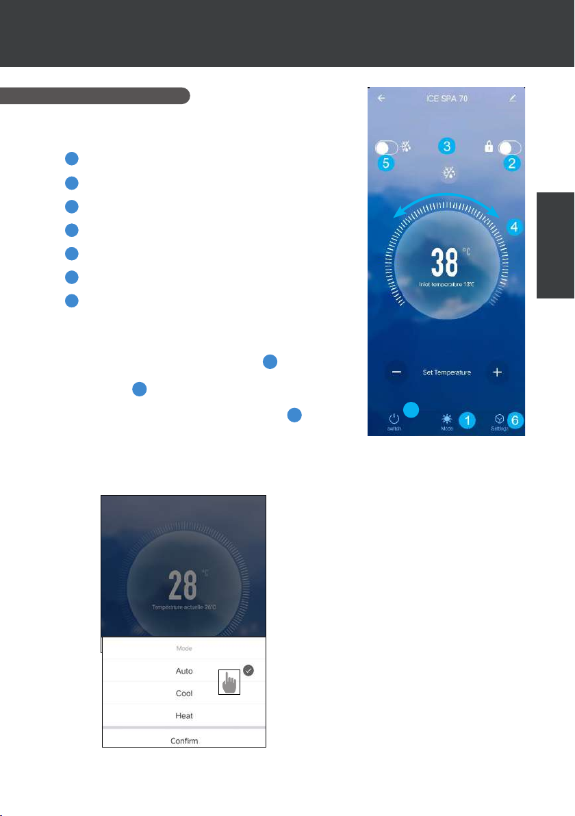
1. User interface
1
Current spa temperature
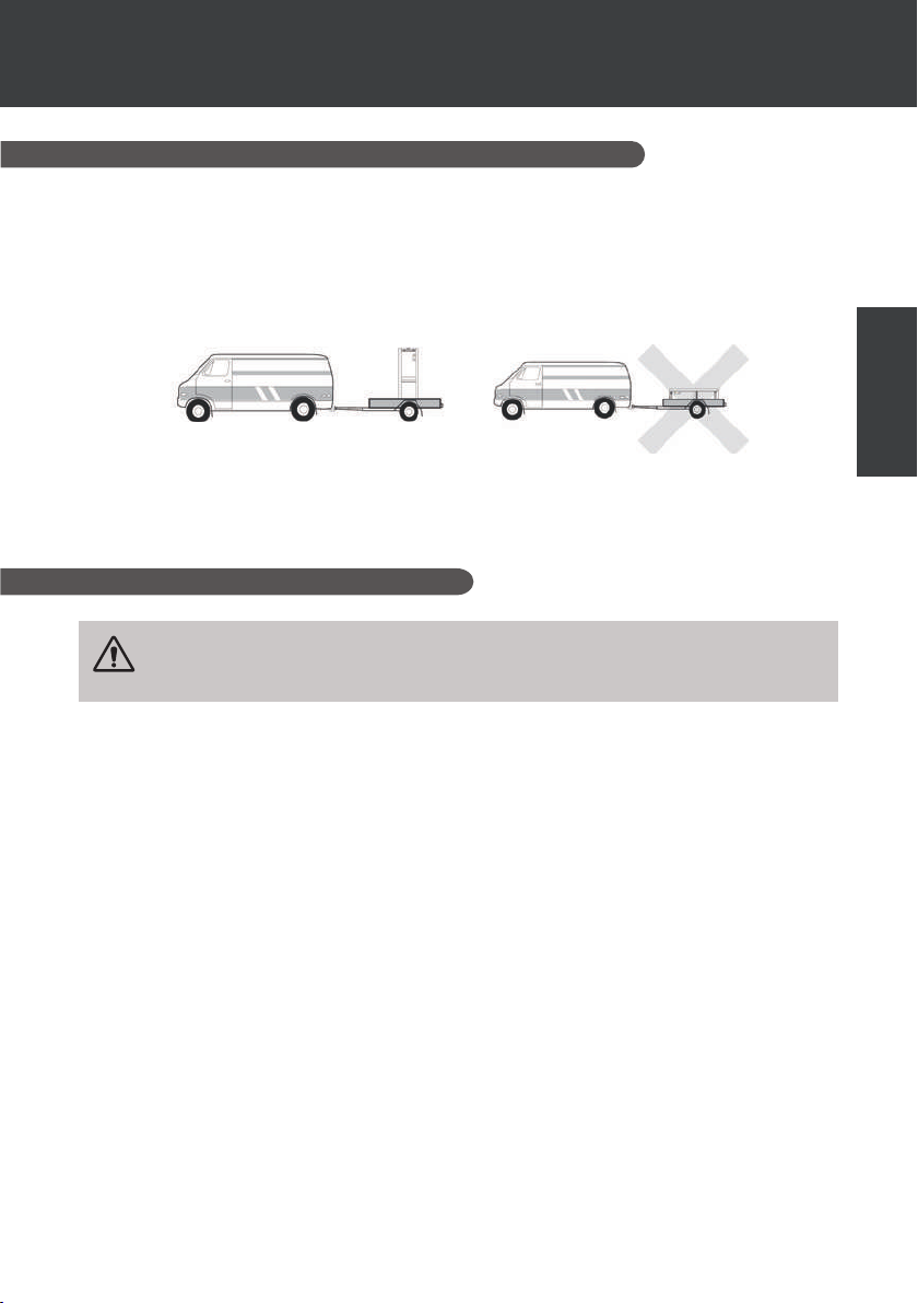
Temperature set point
2
Current operating mode
3
Switch the heat pump on/o
4
Change the temperature
5
Change operating mode
6
Set the operating range
7
To adjust the temperature, you can drag the semi-circular scale
bar or click on "+/-".
When forced defrost
conditions are met, the defrost icon 3 icon is displayed. When
defrosting is complete, the forced defrost button switches o
automatically; if the conditions are not met, the3 is not valid.
If it is not displayed, the forced defrost button will go o after 12
minutes.
is required, activate this button and if the
5
EN
7
2. Heat pump operating mode selector
EN | 27
Page 35
7. USE
VIA MOBILE APPLICATION
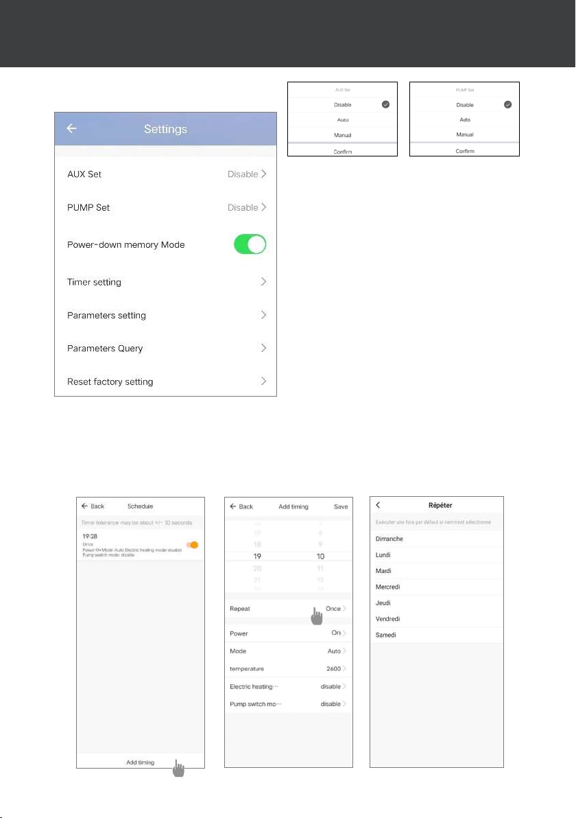
3. About the settings
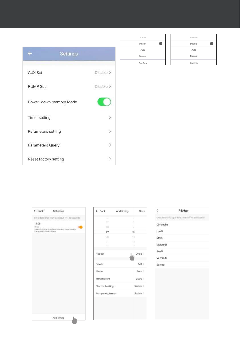
Activating the manual mode (or automatic)
for the SPA heater
Activating the manual mode (or automatic)
for the optional pump
Mode memory during stop
Timer
Parameter settings
Viewing status values
Resetting parameters
4. Setting up the heat pump operating range
The timer allows you to dene several time slots, select the repetition time, switch on and o and the
corresponding mode, set the temperature, as well as the operating mode of the electric heater relay
and the circulation pump.
Create a time schedule: choose the time, the day(s) of the week concerned, the action (switch on or
o) and its details, then save.
28 | EN
Page 36
7. USE
VIA MOBILE APPLICATION
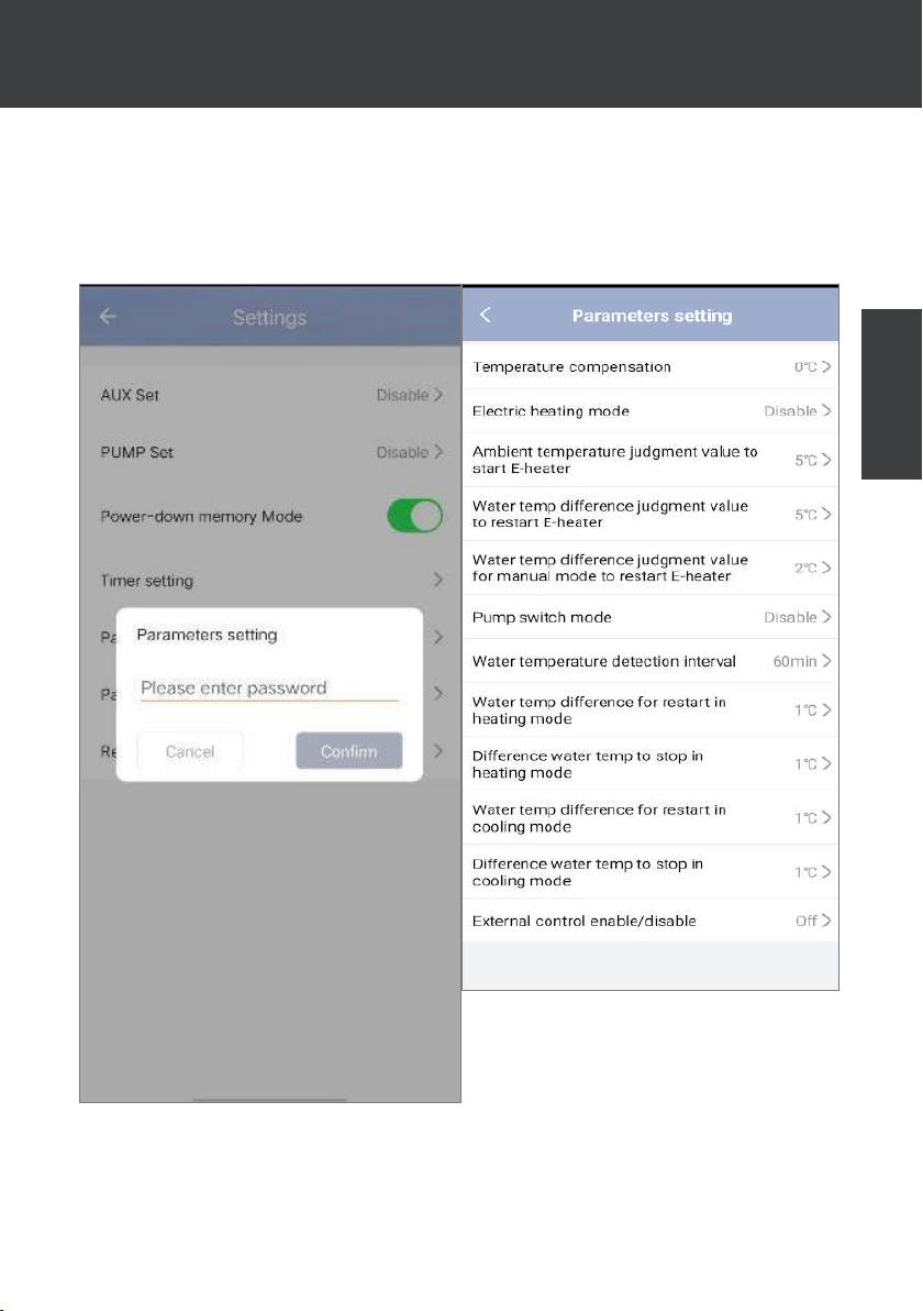
5. Setting parameters
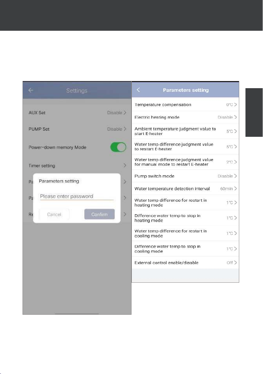
To change the settings, you will be asked for a code: please contact our team to request permission to change the settings and to obtain the code.
Make sure you enter consistent values in the system.
EN
EN | 29
Page 37
7. USE
VIA MOBILE APPLICATION
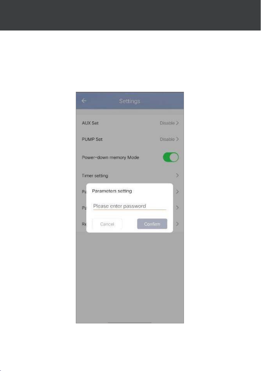
6. Reset settings
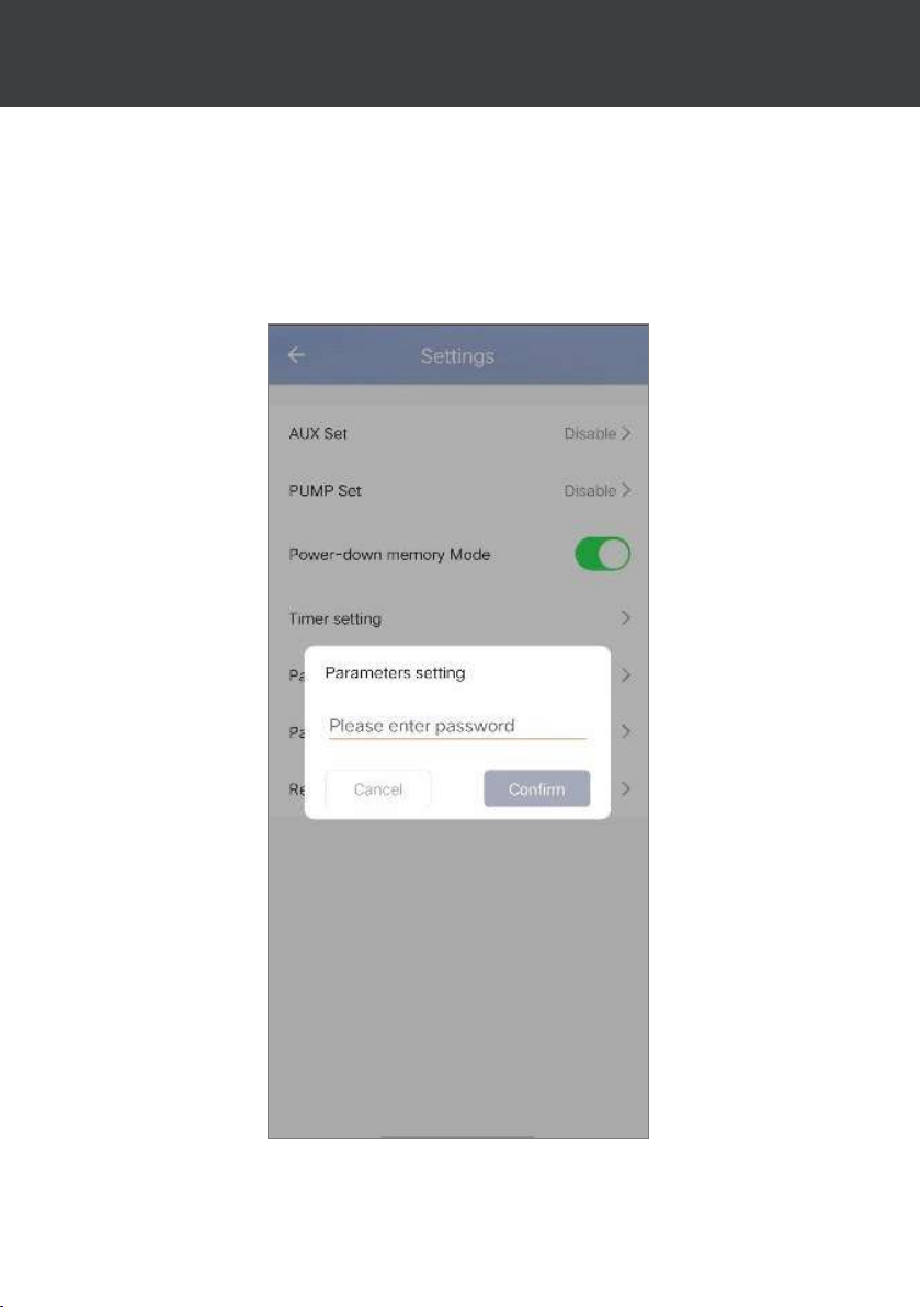
To reset settings, you will be asked for a code: 7416.
After entering the password to reset the parameters, all the parameter setting options are returned
to their default values.
30 | EN
Page 38
7. USE
VIA MOBILE APPLICATION
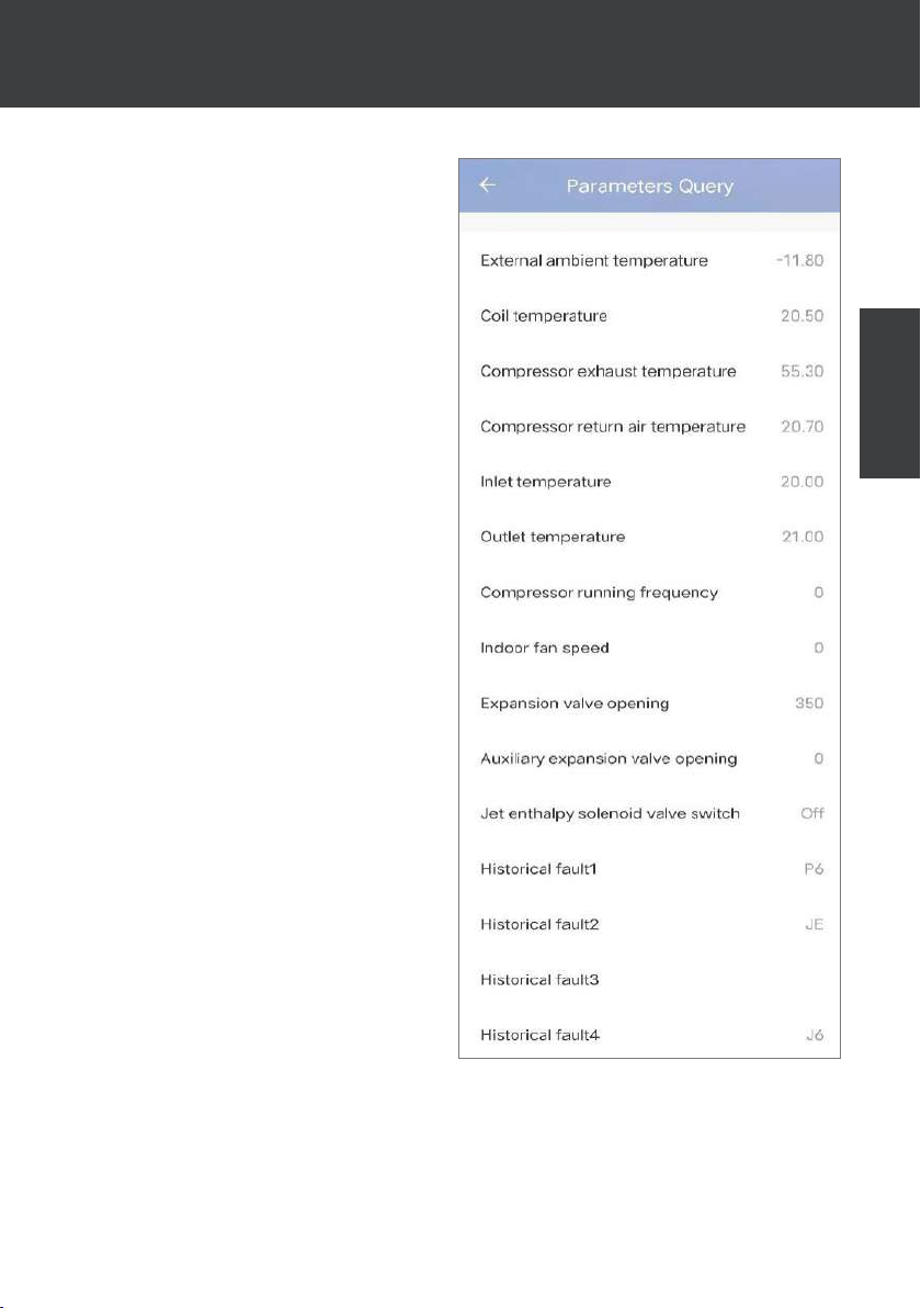
7. Viewing status values
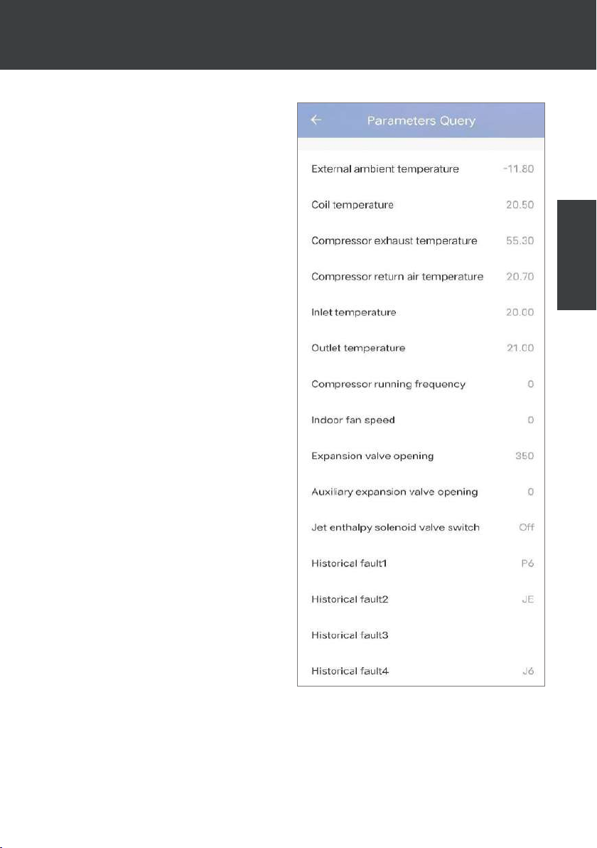
The application lets you view status values in
list form. You will nd:
• Ambient temperature
• Condenser temperature
• Compressor outlet temperature
• Compressor suction temperature
• Inlet temperature
• Outlet temperature
• Compressor operating frequency
• Internal fan speed
• Degree of opening of expansion valve
• Opening degree of auxiliary expansion
valve
• Jet enthalpy solenoid valve switch
• Error history (oldest to most recent)
EN
EN | 31
Page 39
7. USE
VIA MOBILE APPLICATION
8. Upgrade operation
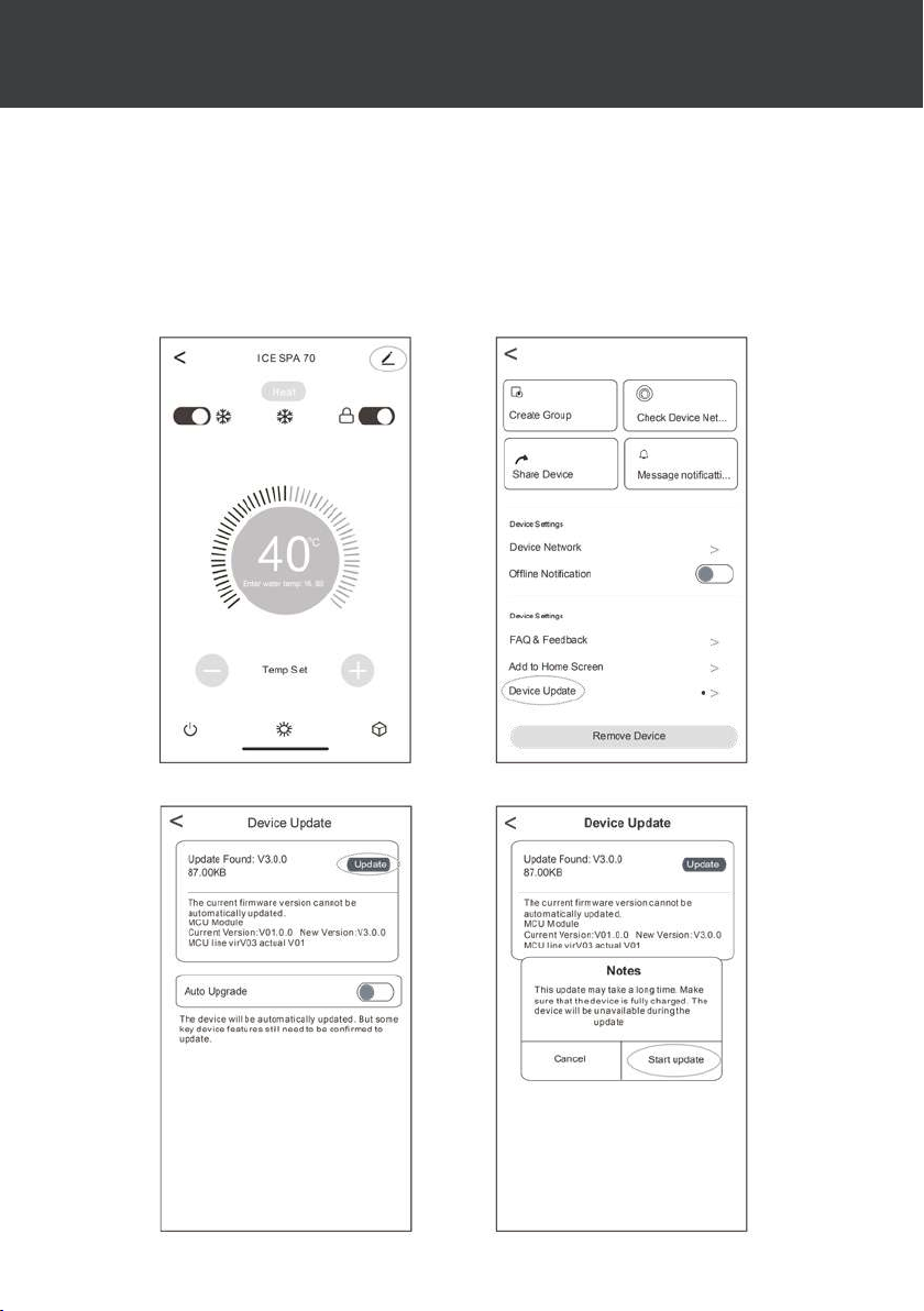
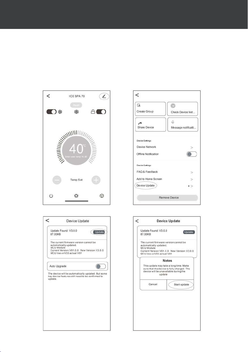
To update your device, follow these steps:
1. Click the edit icon in the upper right corner of the home page
2. Click ‘Device Update’
3. Press ‘Update’
4. Press ‘Start update’
32 | EN
Page 40
8. MAINTENANCE AND REPAIRS
8.1 Maintenance, servicing and winterizing
WARNING: Before undertaking maintenance work on the unit, ensure
that you have disconnected the electrical power supply.
Cleaning
The heat pump housing must be cleaned with a damp cloth. Using detergents or other household
cleaning products may degrade the surface of the housing and aect its integrity.
The evaporator at the rear of the heat pump must be carefully cleaned with a vacuum cleaner and
soft brush attachment.
Annual maintenance
The following operations must be undertaken by a qualied person at least once a year.
Carry out safety checks.
Check the integrity of the electrical wiring.
Check the earthing connections.
Wintering
Your heat pump is designed to operate in all weather. However, if you winterize your SPA, it is
not recommended to leave the heat pump outside for long periods of time (eg over winter). After
draining down the SPA for the winter, uninstall the heat pump and store it in a dry place.
8.2 Checking refrigerant pressure
EN
The gauge is for monitoring the pressure of the refrigerant contained in the heat pump.
The values it indicates can vary considerably, depending on the climate, temperature and atmo-
spheric pressure.
When the heat pump is in operation:
The gauge’s needle indicates the refrigerant pressure.
Mean operating range between 250 and 400 PSI (or about 1.7 to 2.7 MPa), depending on the
ambient temperature and atmospheric pressure.
When the heat pump is shut down:
The needle indicates the same value as the ambient temperature (within a few degrees) and the
corresponding atmospheric pressure (between 150 and 350 PSI maximum, or about 1 to 2.4 MPa).
If left unused for a long period of time:
Check the pressure gauge before starting up the heat pump. It must indicate at least 80 PSI (or
about 0.6 MPa).
If the pressure goes down too much, the heat pump will display an error message
and automatically go into ‘safe’ mode.
This means that there has been a leakage of refrigerant and that you must call a
qualied technician to replace it.
EN | 33
Page 41
8. MAINTENANCE AND REPAIRS
Under normal conditions, a suitable heat pump can heat up the tub water by 1°C to 2°C per
hour. It is therefore normal that you do not feel any dierence in temperature at the outlet
level when the heat pump is on.
A heated tub must be covered and insulated to avoir any heat loss.
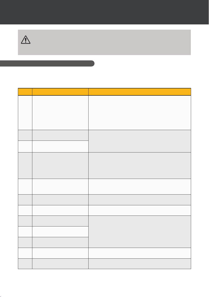
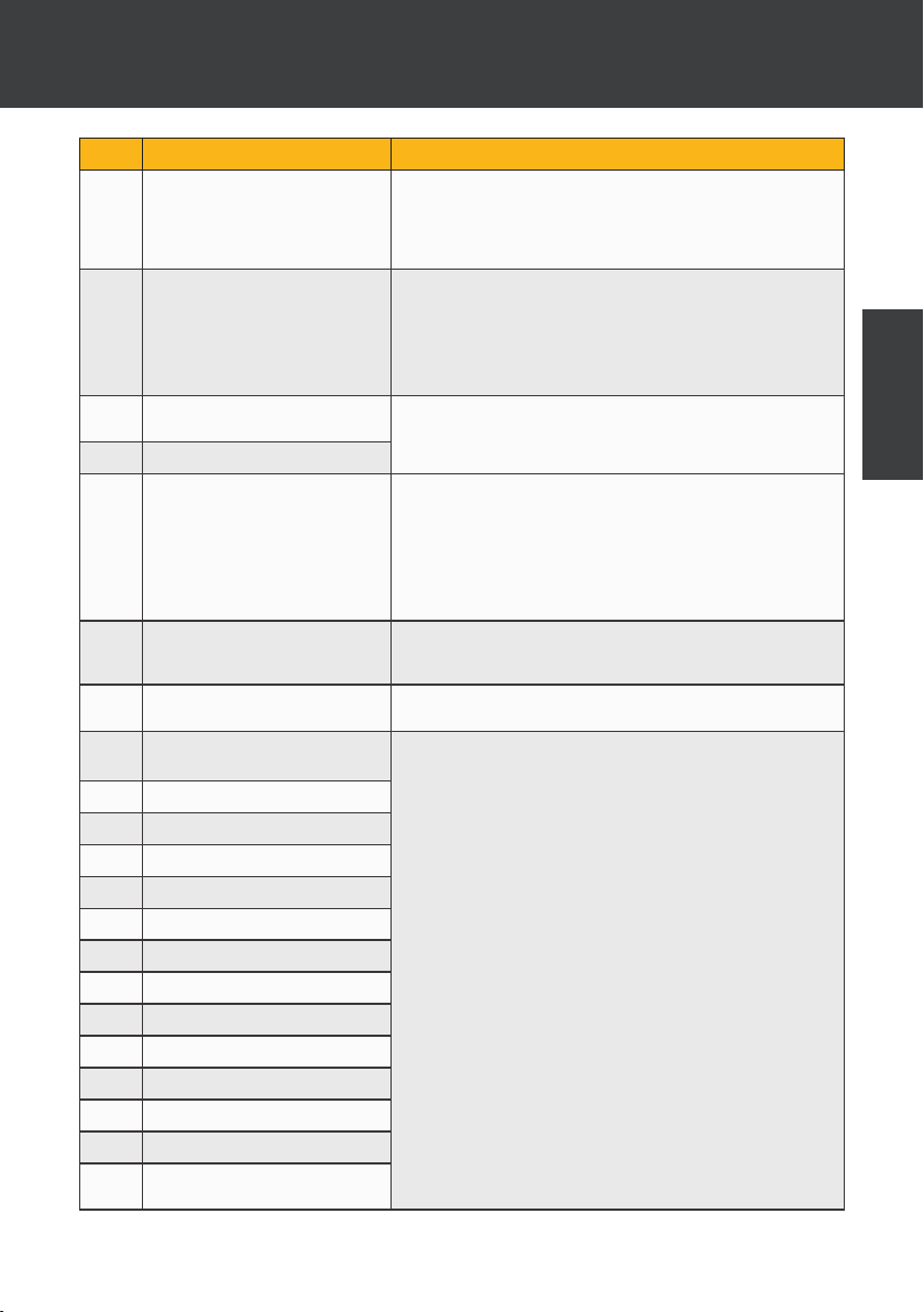
8.3 Breakdown and faults
In the event of a problem, the heat pump’s screen displays an error code instead of temperature
indications. Please consult the table below to nd the possible causes of a fault and the actions to
be taken.
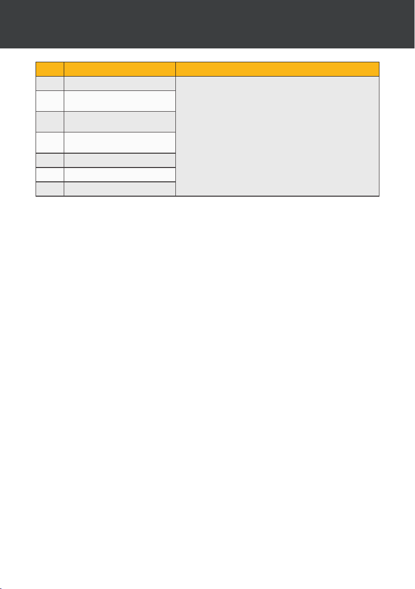
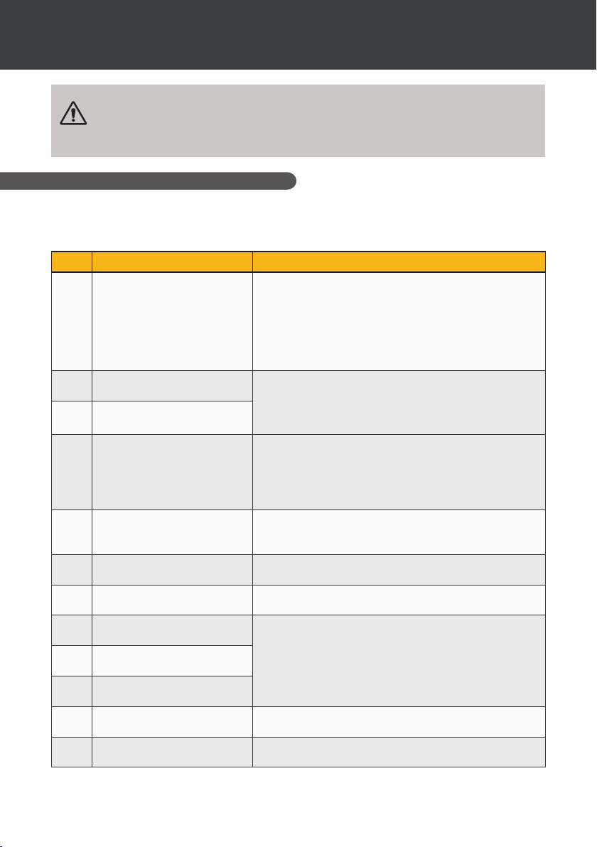
Code Malfunction or protection Troubleshooting
d1
Insufficient water flow fault 1. Check that the water ow switch is not loosely mounted and
d2
Intlet water temperature sensor
failure
d4
Outlet water temperature sensor
failure
d5
The water temperature dierence
between inlet and outlet is
abnormal
d6
Water temperature protection 1.Check whether water ow rate is enough
d7
Anti-freeze in winter 1.The unit is in anti-freeze condition.
C5
Communication failure 1. Check the wire controller connection cable
E3
Outdoor coil temperature
sensor failure T3
E7
Outdoor temperature sensor
failure
E8
Discharge temperature sensor
failure
EC
Communication failure between
drive board and main PCB
EE
Outdoor EEPROM failure 1. Initialize all parameters.
wiring is not loose
2. Check that all stop valves in the water circuit are fully open.
3. Check if the water circuit lter needs to be cleaned.
4. Check the system water resistance to make sure it is not too
high for the pump.
5. Check whether the water level in the titanium tube heat
exchanger meets the requirements.
1. Check the resistance of the sensor.
2. The sensor connector is loosen. Reconnect it.
3. The sensor connector is wet or there is water in. Remove the
water,make the connector dry. Add waterproof adhesive.
4. The sensor failure, change a new sensor.
1.Check that all stop valves in the water circuit are fully open.
2. Check if the water circuit lter needs to be cleaned.
3. Check the system water resistance to make sure it is not too
high for the pump.
4. Check whether the water level in the titanium tube heat
exchanger meets the requirements.
2.Check whether the inlet water temperature sensor and outlet
water temperature sensor are installed in correct positions
2.Auto-recoverable
2. Replace the wire controller
1. Check the resistance of the sensor.
2. The sensor connector is loosen. Reconnect it.
3. The sensor connector is wet or there is water in. Remove the
water,make the connector dry. Add waterproof adhesive.
4. The sensor failure, change a new sensor.
1. Check whether the power supply of the machine is correct
2. main control board is broken, change a new PCB.
34 | EN
Page 42
8. MAINTENANCE AND REPAIRS
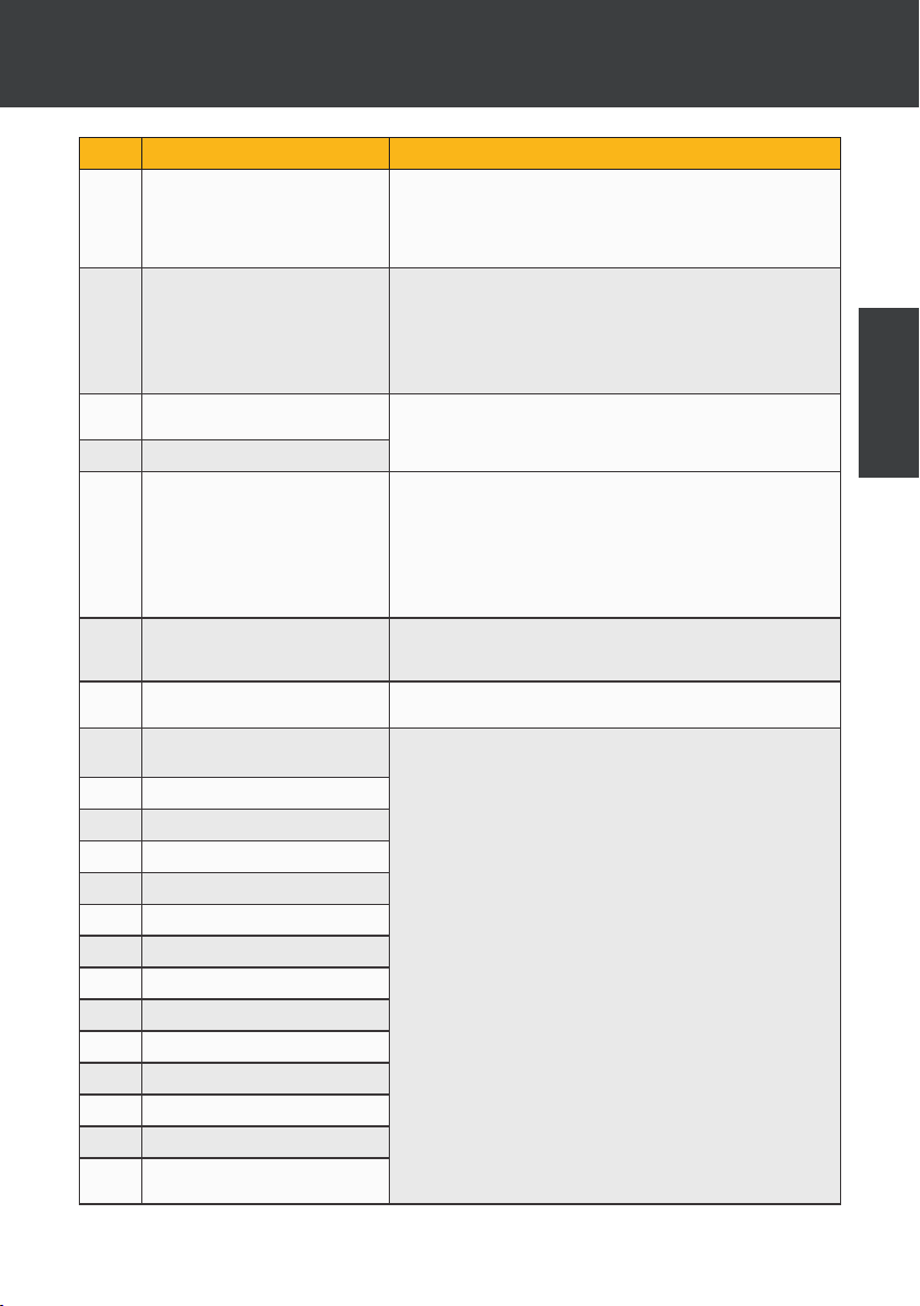
Code Malfunction or protection Troubleshooting
EF
Outdoor DC fan failure 1. Strong wind or typhoon below toward to the fan, to make
EH
Suction temperature sensor
failure
P1
Protection against AC
undervoltage and overvoltage
P2
Protection against overcurrent
P4
Discharge temperature too high
protection
P6
Outdoor coil temperature is too
high in cooling mode
P7
Heating protection against
overheating
J0
Inverter Compressor Operation
Total Fault
J1
IPM overcurrent
J2
Compressor drive failure
J3
Compressor overcurrent
J4
Input voltage out of phase
J5
IPM current sampling failure
J6
Radiator overheat shutdown
J7
Pre-charge failure
J8
DC bus overvoltage
J9
DC bus undervoltage
JA
Undervoltage of AC input
JH
Overcurrent of AC input
JC
Input voltage sampling fault
JL
DSP and PFC communication
fault
thefan running in the opposite direction. Change the unit
direction or make shelter to avoid typhoon below to the fan.
2. Check whether the PWM fan wiring is normal
3. Fan motor is broken, change a new fan motor.
1. Check the resistance of the sensor.
2. The sensor connector is loosen. Reconnect it.
3. The sensor connector is wet or there is water in.
Remove the water,make the connector dry. Add waterproof adhesive.
4. The sensor failure, change a new sensor.
1. Check input power supply-wiring.
2. Check input voltage.
3. Check and replace main control board.
1. Check the resistance of the sensor.
2. The sensor connector is loosen. Reconnect it.
3. The sensor connector is wet or there is water in.
remove the water, make the connector dry. Add waterproof adhesive.
4. The sensor failure, change a new sensor.
5. Check for lack of refrigerant.
Check whether the fin heat exchanger of the unit dissipates heat well during cooling, and whether the condenser is dirty or blocked.
Whether the water flow is sufficient during heating,,
resulting in insufficient water flow.
1. Check input power supply,wiring.
2. Check input voltage.
3. Check and replace.
4. Check whether the working load of the unit is out of range.
5. Check whether there are foreign bodies in the inlet and outlet
of the unit.
6. Check whether the system is blocked
EN
EN | 35
Page 43
8. MAINTENANCE AND REPAIRS
Code Malfunction or protection Troubleshooting
JE
Temperature sensor failure
JF
DSP and communication board
communication fault
JJ
Abnormal communication with
main PCB
JP
IPM module overheating
shutdown
JU
Compressor model failure
Jr
PFC hardware overcurrent
Jy
Driver EE failure
Other problem
✓ The spa ltration pump is running continuously.
» Check the ltration time setting on the spa control box and adjust if necessary.
Tip: Minimum ltration time for an indoor spa is 5 hours, for an outdoor spa 8 hours.
» However, if you wish to reduce this circulation time, adjust the temperature on the spa
control box to the same set temperature as on the heat pump.
1. Check input power supply,wiring.
2. Check input voltage.
3. Check and replace.
4. Check whether the working load of the unit is out of range.
5. Check whether there are foreign bodies in the inlet and outlet
of the unit.
6. Check whether the system is blocked
36 | EN
Page 44

9. WARRANTY
General terms and conditions of warranty
Poolstar guarantees the original owner against material defects and manufacturing defects of
Poolex heat pump for a period of two (2) years.
The compressor is guaranteed for a period of seven (7) years. The titanium coil is guaranteed
against corrosion for a period of fteen (15) years.
The warranty enters into force on the rst billing date.
This warranty does not apply to the following situations:
• Malfunction or damage resulting from installation, use or repair that does not comply with
the safety instructions.
• Malfunction or damage deriving from an unsuitable chemical environment of the spa.
• Malfunction or damage resulting from conditions unsuitable for the intended use of the
device.
• Damage resulting from negligence, accident, or force majeure.
• Malfunction or damage deriving from the use of unauthorized accessories.
Repairs undertaken during the warranty period must be approved before being carried out by a
qualied technician. This warranty is void in the event of repairs to the device made by individuals
which have not been authorised by Poolstar.
The parts under warranty shall be replaced or repaired at the discretion of Poolstar. Faulty parts
must be returned to us during the warranty period in order to be covered. The warranty does not
cover unauthorized labor or replacement costs. Delivery costs for returning the faulty part are not
covered by the warranty.
Dear customer,
A question? A problem? Or simply register your
warranty, nd us on our website:
https://assistance.poolstar.fr/
EN
Thank you for you trust and support. Happy bathing!
Your personal information is processed in accordance with the French Data Protection Act
of 06 January 1978 and will not be shared with 3rd parties.
EN | 37
Page 45

R32. -
.
.
1.
,
.
2.
, , ,
. .
, , ,
.
3.
, .
, ,
, .
4.
’ ,
.
.
5. ’,
,
,
. , ,
, , ,
. ,
. « ».
6. ,
,
.
.
7.
. .
. , ,
:
- , , ;
- ;
- ,
;
- .
;
- ,
- , , .
8.
. , ,
.
:
• : ,
;
• ,
;
• .
UA
Page 46

,
.
.
— .
, ,
Poolex.
UA
UA
Page 47

⚠
,
’ .
. , ,
-:
www.poolex.fr
, ,
.
.
. , ,
, , .
, , -
.
, , ,
.
⚠
/
.
.
.
,
.
, , ,
.
. -
, .
/’
, ,
, ,
, .
UA
Page 48

1. 1
1.1 1
1.2 1
1.3 2
2. 3
2.1 3
2.2 3
2.3 3
2.4 4
2.5 5
2.6 6
3. 7
3.1 7
3.2 8
3.3 8
3.4 8
3.5 9
4. 10
4.5 11
4.6 12
4.7 Wi-Fi 12
4.8 12
4.9 13
4.10 14
4.11 14
5.
5.1 15
5.2 15
5.3 16
5.4 16
5.5 17
5.6 17
5.7 17
5.8 17
5.9 18
1
UA
5
UA
Page 49

5.10 19
5.11 20
6.
6.1 21
6.2 () 22
7.
7.1 «Smart Life» 23
7.2 24
7.3 26
7.4 27
1. 27
2. 27
3. 28
4. 28
5. 29
6. 30
7. 31
8. 32
8.
8.1 , 33
8.2 33
8.3 34
9.
2
2
3
3
1
3
3
7
UA
Page 50
1.
1.1
, , ,
.
, , ,
- , (
, , , ). - ,
,
, 48 .
,
. ,
24 .
1.2
: ,
. , ,
, , .
UA
, ,
.
- (, ,
, )
, .
,
.
,
.
, ,
.
, -
,
.
.
, ,
,
.
.
UA | 1
Page 51

1.
.
.
,
.
.
1. .
2. .
3. / .
4. .
.
.
,
.
,
NF EN12735-1.
1.3
Poolex
. , , ( , pH, /
)
.
, pH
6.8 7.8.
2 | UA
Page 52

2.
2.1
-25 °C 43 °C. ,
10 °C.
,
.
✓ .
✓ .
✓ .
Full Inverter
. ,
( ),
;
.
2.2
, , , :
✓ ICE SPA
✓
✓ 2 ’ 1”
✓ (): ,
✓ 2
✓
✓
UA
2.3
Poolex :
80%
.
, R32.
.
.
.
, -
.
CE.
UA | 3
Page 53
2.
2.4
()
(1)
26°C
()
(2)
26°C
COP (. )
()
(1)
15°C
()
(2)
26°C
COP (. )
()
(1)
15°C
()
(2)
38°C
COP (. )
()
(1)
26°C
()
(2)
38°C
COP (. )
()
(1)
-10°C
()
(2)
38°C
COP (. )
()
(1)
35°C
()
(2)
27°C
EER
3.3~7
0.28~1.4
11.9~5
2.3~5.4
0.35~1.1
6.6~4.9
2.8~4.7
0.67~1.3
4.2~3.7
2.8~6
0.29~1.3
9.6~4.5
2.2~3.3
1.2~1.5
1.8~2.1
3.2~3.7
0.87~1.2
3
220-240V ~ 50Hz
() 1.7
() 9
-25°C ~ 43°C
5 °C ~ 43 °C
-25°C ~ 43°C
x x () 705 x 490 x 505
() 43
1 () < 48
4 () < 36
10 ()
’ ()
(3)
< 28
1" .
(³/) 3.0
GMCC
R32
’ () 650
() 0.1
() 4.3
IPX4
() 3.3
//Auto
.
.
1
2
3
10 EN ISO 3741 EN ISO 354
4 | UA
Page 54
2.5
2.
705 485
505
270
110
: ,
, « », .
UA
UA | 5
Page 55
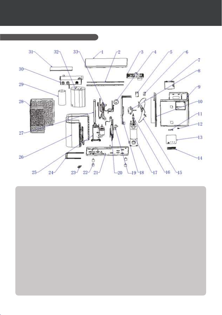
2.
2.6
1.
2.
3.
4.
5.
6.
7.
8.
9.
10.
11.
12.
13.
14.
15.
16.
17.
6 | UA
18.
19.
20.
21.
22.
23.
24.
25.
26.
27.
28.
29. 1
30.
31.
32. 2
33. 4-
Page 56
3.
.
3.1
NF C 15-100
2,5 . , ,
: 1,50
50 .
1,5
.
.
.
.
UA
,
1.
.
2. , .
, .
3. , ,
, .
, ,
.
4. , ,
, ,
.
5. ,
.
6. , ,
, .
7. , .
UA | 7
Page 57
3.
3.2
Slice Valve
SPA ICE 70
Slice Valve
In Grid
/
*
, , ,
, , ’
.
* , ,
.
3.3 ’
1
3.4
10 .
.
.
,
,
,
.
RESET (),
.
: .
8 | UA
2
Page 58

3.
3.5
-25 °C 43 °C.
, :
✓ , .
✓ , 80 psi.
✓ , .
✓ .
✓ , ’ .
✓ ,
.
✓ .
1. .
2. .
3. ( ,
).
4. .
5. , ,
.
6. .
.
UA
:
1–2 °C . ,
, .
, .
:
.
.
UA | 9
Page 59
4.
4.1
/
WiFi
( RECH)
4.2 / /
,
.
, :
,
.
10 | UA
, ,
.
, ,
.
Page 60
4.
4.3
.
WiFi
Wi-Fi.
(. 4.7 “ Wi-Fi”).
. Wi-Fi
.
, :
1. : .
2. : , , ,
.
3. : , , , .
RECH , :
1. : .
2. : , , ,
.
3. : , , , .
4.4
UA
.
, :
• , .
• , .
• , .
, :
:
.
40 °C.
4.5
.
15–40 °C ( 38 °C).
4–35 °C ( 32 °C).
4–40 °C ( 35 °C).
UA | 11
Page 61
4.
4.6
, 30 ,
. ,
«LOC».
3 ,
. .
4.7 Wi-Fi
, 5 ,
Wi-Fi. Wi-Fi .
Wi-Fi . 7 “
”.
4.8
3 ,
. ’ , 3 .
. ,
.
01
02
03
04
05
06
07
A1
A2
A3
A4
A5
E1
E2
E3
E4
E5
12 | UA
(°C)
(°C)
(°C)
(°C)
(°C)
(°C)
()
.
()
()
1 ( )
2
3
4
5 ( )
Page 62
4.
4.9
, 3 ,
. ’ , 3
.
.
:
1. , , .
.
2. .
3. , .
, .
C1
C3
C4
C5
C6
’ 1: ; 0: 1 /
.
0:
-4°C~0°C 0°C
1:
2:
-25°C~20°C 5°C
1°C~5°C 5°C
0:
UA
C7
C8
C9
C10
C11
C12
C13
C14
0:
1°C~5°C 2°C
0:
1:
2:
30~90 60
0°C~10°C 2°C
0°C~10°C 2°C
0°C~10°C 2°C
0°C~10°C 2°C
1:
DOMOSWITCH
0:
1 /
UA | 13
Page 63

4.
4.10
40 °C.
40 °C ,
:
, .
: ,
20 °C, .
4.11
.
8 , .
. 7.3 “
”.
> > > > > , 6 ,
14 | UA
Page 64
5.
5.1
e — ,
.
,
, ( IPX5).
, .
B
12V BG
A
12V
A
G
12V BG
A
5.2
, - . 5
, .
(
5 ), ,
( ,
, ,
, , ).
:
1. 30 °C.
2. ,
3.
4.
UA
, (
, ).
:
1. 30 °C.
2.
UA | 15
Page 65
5.
5.3
,
.
/
Smart-
Boost-
5.4
30 ,
. ( ).
5 , .
, ,
.
16 | UA
Page 66
5.
5.5
.
, P1 0. . 5.10 “ ”.
P2 1,
, 0, . . 5.11 ”
”.
.
15 ,
.
15 ,
.
(15%). P3
( 2)
( 0).
P4 .
5.6
, :
, . ””.
UA
5.7
, :
,
.
5.8
,
’ . ,
.
:
1. , C5.
.
8.3 “ ”.
UA | 17
Page 67
5.
5.9
,
, .
.
:
1. 5 .
2. 30 °C.
,
.
:
1. ,
30 °C.
2. 8 .
3. .
.
:
OR
.
18 | UA
Page 68
5.
5.10
5 , .
, ,
— .
, .
, .
01
02
03
04
05
06
07
A1
A2
A3
A4
A5
E1
E2
E3
E4
E5
(°C)
(°C)
(°C)
(°C)
(°C)
(°C)
()
.
()
()
1 ( )
2
3
4
5 ( )
UA
UA | 19
Page 69
5.
5.11
1. 5 ,
.
,
, — .
, .
2. ,
.
( ) .
3. , ,
,
.
N°
’ 1: ; 0: 1 /
C1
C3
0 :
C4
-25°C~20°C 5°C
C5
C6
C7
0 :
C8
30~90 60
C9
.
C10
0°C~10°C
C11
.
C12
C13
C14
P1
/
P2
/
P3
P4
30%~100% 100%
P5
01/02 02
-4°C~0°C 0°C
1 :
2 :
1°C~5°C 5°C
1°C~5°C 2°C
1 :
2 :
0°C~10°C 2°C
0°C~10°C 2°C
0°C~10°C 2°C
0 :
1: In.grid
0 : .
1 : . / 50% / 15%
2 : . / 50% / .
.
0
0
2°C
1 /
1
20 | UA
Page 70
*
*
6.
6.1
Poolex
240VAC 30A
125VAC 30A
250VAC 15A cos Ø = 0.4
3 230
(230 , 50 , 30 ),
(
).
().
,
.
.
- :
( C5: ,
-25 20 °C)
( C6, 1 5 °C),
. ,
.
- : ,
( C7,
1 5 °C), . ,
.
:
C4 = 1, , C4 = 2,
(. 4.9 “” “
”).
’
(* )
UA
UA | 21
Page 71
*
*
6.
6.2 ()
Poolex
240VAC 30A
125VAC 30A
250VAC 15A cos Ø = 0.4
L
N
’
(* )
.
’
3 ³/.
: 60 (
30 90 , C9)
.
,
, 60 ( 30
90 , C9) .
: , .
:
C8 = 1, (. 4.9 “”
“ ”).
, C9 ( 30 90
).
22 | UA
Page 72
7.
7.1 «Smart Life»
Smart Life:
«Smart
Life».
«Smart Life» - .
.
- Smart Life,
.
- .
- ,
( ).
“Help” ()
“Smart Life”.
“Smart Life” Hangzhou Tuya Technology.
Poolstar, ’ Poolex,
“Smart Life”.
Poolstar “Smart Life”.
«Smart Life»,
, , «Tuya
Smart».
iOS:
«Smart Life» App Store, :
UA
Download from
Smart Life
.
Android:
«Smart Life» Play Store, :
Download from
Smart Life
.
UA | 23
Page 73
7.
7.2
: ,
«Smart Life», WiFi,
.
«Smart
Life». Smart Life,
3.
1: « »
« » «»,
.
« ».
2: , ,
24 | UA
.
, «Smart Life».
Page 74
7.
3 (): ’, «...», « ’».
(, «») «».
4: «».
«» «+», « ...» «».
«»
.
UA
UA | 25
Page 75
7.
7.3
1: .
WiFi, WiFi
«».
: «Smart Life» WiFi
2,4 .
WiFi 5 ,
WiFi, WiFi
2,4 ( -,
WiFi).
2: .
,
5 , WiFi.
WiFi .
Wi-Fi,
Wi-Fi ( ).
. Poolex,
«».
, .
26 | UA
Page 76
777...
7.4
1.
1
2
3
/
4
5
6
7
«+/-».5
5 ,
, , ’
3 .
; , 3
. ,
12 .
UA
7
2.
UA | 27
Page 77
7.
3.
(
)
(
)
’
4.
, ,
, ,
.
: , () , ( )
, .
28 | UA
Page 78
7.
5.
:
.
, .
UA
UA | 29
Page 79
7.
6.
: 7416.
.
30 | UA
Page 80
7.
7.
.
•
•
•
•
•
•
•
•
•
•
•
• (
)
UA
UA | 31
Page 81
7.
8.
:
1. .
2. ‘Device Update’ ( )
3. ‘Update’ ()
4. ‘Start update’ ( )
32 | UA
Page 82
8.
8.1 ,
:
, .
.
.
’ .
.
.
.
.
- . ,
,
(, ). , ,
.
8.2
, .
, , ,
.
:
.
250 400 PSI ( 1,7 2,7 ),
.
:
, (
) ( 150 350 PSI ,
1 2,4 ).
UA
:
. 80 PSI
( 0,6 ).
,
«» .
, ,
.
UA | 33
Page 83
8.
1–2 °C
. , ,
.
, .
8.3
. ,
.
d1
d2
d4
d5
d6
d7
C5
’
E3
.
T3
E7
E8
’
EC
.
EE
EEPROM
1. , .
2. ,
.
3. , .
4. , ,
.
5. ,
.
1. .
2. ’ . .
3. ’ .
, ’. .
4. , .
1. ,
.
2. , .
3. , ,
.
4. ,
.
1.,
2. ,
1. .
2.
1.
2.
1. .
2. ’ . .
3. ’ .
, ’.
.
4. , .
1. , .
1. .
2. , .
34 | UA
Page 84
8.
EF
EH
P1
.
P2
P4
P6
P7
,
J0
J1
IPM
J2
.
J3
J4
J5
IPM
J6
J7
J8
.
.
J9
JA
JH
JC
JL
’ DSP PFC
1.
.
, .
2. , PWM.
3. , .
1. .
2. ’ . .
3. ’ .
, ’.
.
4. , .
1. .
2. .
3. .
1. .
2. ’ . .
3. ’ .
, ’.
.
4. , .
5. , .
,
,
.
.
1. , .
2. .
3. .
4. ,
.
5. ,
.
6. , .
UA
UA | 35
Page 85
8.
JE
JF
’ DSP
’
JJ
JP
IPM
JU
Jr
PFC
Jy
EE
✓ .
»
.
: 5 ,
— 8 .
» , ,
,
.
1. , .
2. .
3. .
4. ,
.
5. ,
.
6. , .
36 | UA
Page 86

9.
Poolstar
Poolex (2) .
(7) .
’ (15) .
.
:
• , ,
, .
• ,
.
• , ,
.
• , , -
.
• ,
.
, ,
.
, Poolstar.
, ,
Poolstar. ,
.
. .
,
? ?
? -:
https://assistance.poolstar.fr/
UA
. !
6 1978 .
UA | 37
Page 87

UWAGA
PL
Niniejsza pompa ciepła zawiera łatwopalny czynnik chłodniczy R32. Zabrania się jakiejkolwiek
ingerencji w układ chłodniczy bez posiadania odpowiednich uprawnień. Przed przystąpieniem
do prac przy układzie chłodniczym należy podjąć niezbędne środki ostrożności w celu
zapewnienia bezpieczeństwa.
1. Procedura pracy
Prace należy wykonywać zgodnie z ustaloną procedurą, aby zminimalizować ryzyko obecności łatwopalnych gazów
lub oparów w trakcie ich wykonywania.
2. Ogólny obszar roboczy
Wszystkie osoby znajdujące się w obszarze roboczym muszą zostać poinformowane o charakterze wykonywanych
prac.Należy unikać pracy w przestrzeniach zamkniętych.Obszar wokół miejsca wykonywania prac powinien zostać
wydzielony i zabezpieczony. Należy zwrócić szczególną uwagę na znajdujące się w pobliżu źródła ognia lub ciepła.
3. Kontrola obecności czynnika chłodniczego
Przed rozpoczęciem pracy oraz w jej trakcie należy skontrolować obszar za pomocą odpowiedniego detektora
czynnika chłodniczego, aby upewnić się o braku potencjalnie łatwopalnych gazów.Należy upewnić się, że sprzęt do
wykrywania wycieków jest odpowiedni do stosowania z łatwopalnymi czynnikami chłodniczymi, tzn. nie wytwarza
iskier, jest odpowiednio uszczelniony lub posiada właściwe zabezpieczenia wewnętrzne.
4. Dostępność gaśnicy
W przypadku wykonywania prac gorących na urządzeniach chłodniczych lub powiązanych z nimi elementach, należy
zapewnić łatwy dostęp do odpowiedniego sprzętu gaśniczego.W pobliżu strefy napełniania powinna znajdować się
gaśnica proszkowa lub śniegowa (CO2).
5. Brak źródeł ognia, ciepła i iskier
Bezwzględnie zabrania się używania źródeł ciepła, otwartego ognia lub iskier w bezpośrednim sąsiedztwie
elementów lub rurociągów, które zawierają lub zawierały łatwopalny czynnik chłodniczy.Wszelkie źródła zapłonu, w
tym palenie tytoniu, muszą znajdować się w bezpiecznej odległości od miejsca instalacji, naprawy, demontażu i
utylizacji, podczas których łatwopalny czynnik chłodniczy może przedostać się do otoczenia.Przed rozpoczęciem
prac należy upewnić się, że w pobliżu urządzenia nie występują żadne źródła zapłonu.Należy umieścić znaki „Zakaz
palenia”.
6. Obszar wentylowany
Przed otwarciem układu lub wykonaniem prac gorących należy upewnić się, że prace będą prowadzone na otwartej
przestrzeni lub że pomieszczenie posiada odpowiednią wentylację.Podczas wykonywania prac należy również
zapewnić ciągłość wentylacji.
7. Kontrola urządzeń chłodniczych
W przypadku wymiany podzespołów elektrycznych, muszą one być odpowiednio dobrane do przeznaczenia i zgodne
ze specyfikacją techniczną.Należy stosować wyłącznie oryginalne części producenta.W razie wątpliwości należy
skonsultować się z działem technicznym producenta.W przypadku instalacji wykorzystujących łatwopalne czynniki
chłodnicze należy przeprowadzić następujące czynności kontrolne:
- Wielkość napełnienia musi być dostosowana do kubatury pomieszczenia, w którym zainstalowane są elementy
zawierające czynnik chłodniczy;
- Urządzenia wentylacyjne i wyloty muszą działać prawidłowo i nie mogą być zasłonięte;
- W przypadku stosowania pośredniego obiegu chłodniczego, obieg wtórny należy sprawdzić pod kątem obecności
czynnika chłodniczego;
- Oznakowanie urządzenia musi być widoczne i czytelne.Nieczytelne oznaczenia i znaki należy odnowić;
- Rurociągi lub komponenty chłodnicze muszą być zainstalowane w miejscu, w którym ryzyko narażenia na działanie
substancji mogących powodować korozję elementów zawierających czynnik chłodniczy jest minimalne.
8. Kontrola urządzeń elektrycznych
Naprawa i konserwacja podzespołów elektrycznych muszą obejmować wstępne kontrole bezpieczeństwa oraz
procedury inspekcji komponentów.W przypadku stwierdzenia usterki, która mogłaby zagrażać bezpieczeństwu, nie
należy podłączać zasilania do obwodu aż do momentu usunięcia problemu.
Wstępne kontrole bezpieczeństwa muszą obejmować:
• Zapewnienie pełnego rozładowania kondensatorów:czynność tę należy wykonać w bezpieczny sposób, aby uniknąć
ryzyka iskrzenia;
• Brak odsłoniętych elementów elektrycznych pod napięciem oraz okablowania podczas napełniania, odzysku
czynnika lub oczyszczania układu;
• Ciągłość uziemienia.
Page 88

PODZIĘKOWANIA
PL
Szanowny Kliencie,
PL
Dziękujemy za wybranie naszego produktu i zaufanie, jakim nas obdarzyłeś.
Nasze produkty są wynikiem wieloletnich badań w dziedzinie projektowania i produkcji pomp
ciepła do basenów.
Naszym celem jest dostarczanie produktów wysokiej jakości o wyjątkowej wydajności.
Dołożyliśmy wszelkich starań, przygotowując ten podręcznik, aby mogli
Państwo uzyskać maksymalne korzyści z nowej pompy ciepła Poolex.
Page 89

PL
Niniejsza instrukcja montażu jest integralną częścią
⚠
PROSIMY O UWAŻNE PRZECZYTANIE
⚠
Wszelka odpowiedzialność umowna i pozaumowna ze strony producenta/dystrybutora staje się
nieważna w przypadku szkód spowodowanych błędami podczas instalacji lub eksploatacji, albo z
powodu nieprzestrzegania instrukcji zawartych w niniejszym podręczniku lub obowiązujących norm
dotyczących instalacji sprzętu omawianego w tym dokumencie.
produktu.Musi zostać przekazana instalatorowi i być
przechowywana przez użytkownika w bezpiecznym miejscu.Jeśli
utracą Państwo ten podręcznik, prosimy o odwiedzenie naszej
strony internetowej:
www.poolex.fr
Należy uważnie przeczytać i zrozumieć wskazówki oraz ostrzeżenia zawarte w niniejszej instrukcji,
ponieważ zawierają one ważne informacje dotyczące bezpiecznej eksploatacji pompy ciepła.
Prosimy o zachowanie tej instrukcji do wglądu w przyszłości.
Instalacja musi być wykonana przez wykwalifikowanego specjalistę zgodnie z obowiązującymi
normami i instrukcjami producenta. Błędy popełnione podczas montażu mogą prowadzić do obrażeń
ciała ludzi i zwierząt oraz uszkodzeń mechanicznych, za które producent nie ponosi
odpowiedzialności.
Po rozpakowaniu pompy ciepła należy sprawdzić zawartość pod kątem ewentualnych uszkodzeń.
Przed podłączeniem pompy ciepła upewnij się, że instrukcje zawarte w niniejszym podręczniku
odpowiadają faktycznym warunkom instalacji i nie przekraczają maksymalnie dopuszczalnych
ograniczeń dla danego produktu.
W przypadku usterki i/lub nieprawidłowego działania pompy ciepła, należy wyłączyć zasilanie
elektryczne i nie podejmować żadnych prób usunięcia awarii.Naprawy muszą być wykonywane
przez upoważnionego technika z użyciem oryginalnych części zamiennych.Nieprzestrzeganie
powyższych postanowień może negatywnie wpłynąć na bezpieczne działanie pompy ciepła.
Aby zagwarantować efektywność i zapewnić prawidłowe funkcjonowanie pompy ciepła, należy ją
regularnie serwisować zgodnie z dostarczonymi instrukcjami.
W przypadku sprzedaży lub przekazania pompy ciepła stronie trzeciej, prosimy upewnić się, że cała
dokumentacja techniczna została przekazana nowemu właścicielowi wraz ze sprzętem.
Niniejsza pompa ciepła została zaprojektowana wyłącznie do podgrzewania wody basenowej.Każde
inne użycie uważa się za niewłaściwe, nieprawidłowe i potencjalnie niebezpieczne.
Page 90

PL
SPIS
1.INFORMACJE OGÓLNE
1
2.Opis
3
3.Montaż
7
4.Obsługa panelu sterowania
10
5.Obsługa sterownika przewodowego
15
PL
Ogólne warunki dostawy __________________________________________________ 1
Instrukcje dotyczące bezpieczeństwa ________________________________________ 1
Uzdatnianie wody 2
Ograniczenia eksploatacyjne ______________________________________________ 3
Zawartość opakowania ___________________________________________________ 3
Charakterystyka ogólna __________________________________________________ 3
Dane techniczne ________________________________________________________ 4
Wymiary produktu _______________________________________________________ 5
Widok rozstrzelony (rysunek złożeniowy) _____________________________________ 6
Lokalizacja ____________________________________________________________ 7
Schemat instalacji _______________________________________________________ 8
Podłączenie hydrauliczne ________________________________________________ 8
Podłączenie elektryczne _________________________________________________ 8
Uruchomienie __________________________________________________________ 9
Ustawianie temperatury zadanej____________________________________________ 11
Blokowanie i odblokowywanie _____________________________________________ 12
Połączenie Wi-Fi ________________________________________________________ 12
Podgląd parametrów pracy _______________________________________________ 12
Ustawienia ____________________________________________________________ 13
Wymuszone odszranianie ________________________________________________ 14
Wyświetlanie błędów _____________________________________________________ 14
Instalacja ______________________________________________________________ 15
Uruchomienie __________________________________________________________ 15
Panel sterowania _______________________________________________________ 16
Odblokowywanie ________________________________________________________ 16
Ustawienia dźwięku i podświetlenia _________________________________________ 17
Ustawianie temperatury __________________________________________________ 17
Wybór trybu pracy _______________________________________________________ 17
Wyświetlanie błędów_____________________________________________________ 17
Programator czasowy ____________________________________________________ 18
Page 91

SPIS
PL
6.Obsługa dodatkowych przekaźników sterujących
21
7.Obsługa przez aplikację mobilną
23
8.KONSERWACJA I NAPRAWA
33
9.Gwarancja
37
Para metry stanu _______________________________________________________ 19
Ustawienia użytkownika __________________________________________________ 20
Sterowanie podgrzewaczem SPA___________________________________________ 21
Sterowanie pompą cyrkulacyjną (opcjonalnie) _________________________________ 22
Pobieranie i instalacja aplikacji „Smart Life” ___________________________________ 23
Konfiguracja aplikacji ____________________________________________________ 24
Podłączanie pompy ciepła ________________________________________________ 26
Sterowanie 27
1. Interfejs użytkownika ____________________________________________________ 27
2. Zmiana trybu pracy pompy ciepła __________________________________________ 27
3. Informacje o ustawieniach ________________________________________________ 28
4. Ustawianie zakresu pracy pompy ciepła _____________________________________ 28
5. Ustawienia parametrów __________________________________________________ 29
6. Reset ustawień ________________________________________________________ 30
7. Podgląd parametrów pracy _______________________________________________ 31
8. Aktualizacja ___________________________________________________________ 32
Konserwacja, naprawa i przygotowanie do zimy _______________________________ 33
Sprawdzanie ciśnienia czynnika chłodniczego _________________________________ 33
Usterki i rozwiązywanie problemów _________________________________________ 34
Page 92
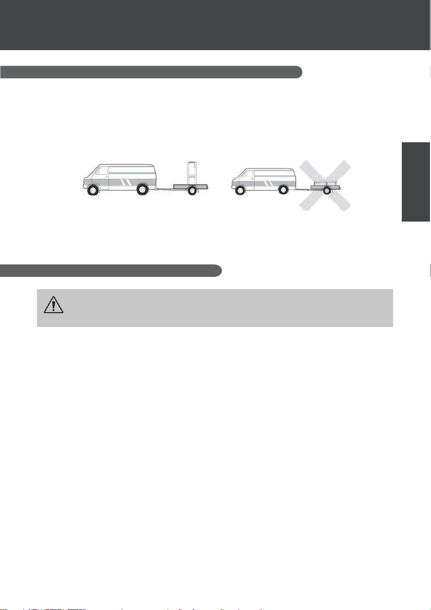
PL | 1
1.INFORMACJE OGÓLNE
PL
1.1
Zasady bezpieczeństwa
UWAGA:Prosimy o uważne przeczytanie wszystkich instrukcji bezpieczeństwa
przed użyciem urządzenia.Ponieważ instrukcje zawarte w tym dokumencie są
kluczowe dla Państwa bezpieczeństwa, prosimy o ich dokładne przestrzeganie.
Wszystkie produkty i opakowania, nawet te wysyłane z opłaconą dostawą, są transportowane
na odpowiedzialność odbiorcy.
Osoba odbierająca urządzenie zobowiązana jest do przeprowadzenia oględzin w celu
stwierdzenia ewentualnych uszkodzeń, które mogły powstać podczas transportu (obieg
chłodniczy, obudowa, skrzynka elektryczna, rama).Wszelkie uszkodzenia transportowe muszą
zostać odnotowane przez odbiorcę na liście przewozowym oraz potwierdzone listem
poleconym wysłanym do przewoźnika w ciągu 48 godzin.
Urządzenie należy przechowywać i transportować w pozycji pionowej, na palecie i w
oryginalnym opakowaniu.Jeśli urządzenie było transportowane w pozycji poziomej, należy
odczekać co najmniej 24 godziny przed jego podłączeniem.
Ogólne warunki dostawy
1.2
Instalacja i serwisowanie
Tylko wykwalifikowany specjalista może przeprowadzać montaż, uruchomienie, konserwację i
naprawy zgodnie z obowiązującymi normami.
Przed eksploatacją lub wykonaniem jakichkolwiek prac na urządzeniu (instalacja, uruchomienie,
użytkowanie, konserwacja) osoba odpowiedzialna musi zapoznać się ze wszystkimi instrukcjami
zawartymi w podręczniku montażu pompy ciepła, a także z danymi technicznymi.
Pod żadnym pozorem nie instaluj urządzenia w pobliżu źródła ciepła, materiałów palnych lub wlotu
powietrza do budynku.
Jeśli montaż odbywa się w miejscu o ograniczonym dostępie, należy zainstalować kratę ochronną
dla pompy ciepła.
Aby uniknąć poważnych oparzeń, nie stąpaj po rurociągach podczas instalacji, naprawy lub
konserwacji.
Aby uniknąć poważnych oparzeń, przed przystąpieniem do jakichkolwiek prac przy układzie
chłodniczym, wyłącz pompę ciepła i odczekaj kilka minut przed zamontowaniem czujników
temperatury i ciśnienia.
Sprawdzaj poziom czynnika chłodniczego podczas serwisowania pompy ciepła.
Sprawdź, czy presostaty wysokiego i niskiego ciśnienia są prawidłowo podłączone do układu
chłodniczego oraz czy odłączają obwód elektryczny w przypadku zadziałania podczas corocznej
kontroli szczelności urządzenia.
Sprawdź, czy nie ma śladów korozji lub plam oleju wokół komponentów układu chłodniczego.
Page 93

1.INFORMACJE OGÓLNE
2 | PL
Podczas użytkowania
Nie dotykaj otworu wentylacyjnego podczas pracy ze względu na ryzyko poważnych obrażeń.
Nie pozostawiaj pompy ciepła w miejscu dostępnym dla dzieci ze względu na ryzyko zranienia się
przez lamele (żeberka) wymiennika ciepła.
Nigdy nie uruchamiaj urządzenia, jeśli w basenie nie ma wody lub jeśli pompa obiegowa jest
zatrzymana.Sprawdzaj natężenie przepływu wody co miesiąc i w razie potrzeby wyczyść filtr.
Podczas czyszczenia
1.
2.
3.
4.
Odłącz zasilanie urządzenia.
Zamknij zawory wlotowe i wylotowe wody.
Nie wkładaj niczego do otworów wlotu/wylotu wody ani powietrza.
Nie spryskuj urządzenia nadmierną ilością wody.
Podczas naprawy
Wykonuj prace przy układzie chłodniczym zgodnie z obowiązującymi przepisami
bezpieczeństwa.Lutowanie musi być wykonywane przez wykwalifikowanego
spawacza/lutownika.
Podczas wymiany uszkodzonego elementu układu chłodniczego używaj wyłącznie części
certyfikowanych przez nasz dział techniczny.
Podczas wymiany rurociągów w celu naprawy można używać tylko rur miedzianych zgodnych z
normą NF EN12735-1.
Uzdatnianie wody
1.3
Pompy ciepła Poolex do basenów mogą być używane ze wszystkimi typami systemów
uzdatniania wody.Niemniej jednak, ważne jest, aby system uzdatniania (pompy dozujące chloru,
pH, bromu i/lub chlorator solny) był zainstalowany za pompą ciepła w obiegu hydraulicznym.
Aby uniknąć pogorszenia działania pompy ciepła, pH wody musi być utrzymywane w
zakresie od 6.8 do 7.7.
Page 94

PL | 3
2.OPIS
PL
2.1
Ograniczeniaeksploatacyjne
Aby zapewnić prawidłowe działanie pompy ciepła, temperatura powietrza otoczenia musi mieścić
się w zakresie od -25°C do 43°C.Zalecamy jednak przygotowanie wanny SPA do zimy
(zimowanie), jeśli temperatura wody spadnie poniżej 10°C.
Aby pompa ciepła mogła pracować w optymalnym trybie, wanna z hydromasażem (SPA) musi
być odpowiednio zaizolowana.
✓ Wanna musi posiadać izolację.
✓ Rurociągi muszą być izolowane.
✓ Wanna z hydromasażem musi być wyposażona w pokrywę izolacyjną.
Dzięki technologii Full Inverter pompa ciepła do SPA automatycznie dostosowuje swoją moc do
ustawień oraz warunków zewnętrznych.W związku z tym, podczas podnoszenia temperatury
wody (faza ta może trwać do tygodnia od momentu instalacji), pompa ciepła będzie
wykorzystywać pełną dostępną moc. Po osiągnięciu zadanej temperatury pompa ciepła zmniejszy
zużycie energii.
Zawartość opakowania
2.2
Podczas odbioru towaru prosimy sprawdzić, czy opakowanie zawiera:
✓ Pompę ciepła ICE SPASPA
✓ Pokrowiec zimowy
✓ 2 złączki gwintowane 1” z gwintem zewnętrznym
✓ Zdalny wodoodporny panel sterowania (opcjonalnie):sterownik, obudowa i kabel
✓ 2 przekaźniki sterujące
✓ Wąż hydrauliczny
✓ Kolanko hydrauliczne
2.3
Pompa ciepła Poolex ma następujące cechy:
Charakterystyka ogólna
Wysoka wydajność z oszczędnością energii do 80% w porównaniu ze
standardowym systemem grzewczym.
Ekologiczny, wydajny i czysty czynnik chłodniczy R32.
Niezawodna, wysokowydajna sprężarka wiodącej marki.
Duży parownik z hydrofilowego aluminium, przystosowany do pracy w niskich
temperaturach.
Wygodny i intuicyjny panel sterowania.
Wytrzymała obudowa z powłoką chroniącą przed promieniowaniem UV, łatwa w
konserwacji.
Certyfikat CE.
Page 95
2.OPIS
4 | PL
ICE SPA 70
Powietrze
(1)
26°C
Woda
(2)
26°C
Moc grzewcza(kW)
3.3~7
Zużycie (kW)
0.28~1.4
COP (wsp. wydajności)
11.9~5
Powietrze
(1)
15°C
Woda
(2)
26°C
Moc grzewcza (kW)
2.3~5.4
Zużycie (kW)
0.35~1.1
COP (wsp. wydajności)
6.6~4.9
Powietrze
(1)
15°C
Woda
(2)
38°C
Moc grzewcza (kW)
2.8~4.7
Zużycie (kW)
0.67~1.3
COP (wsp. wydajności)
4.2~3.7
Powietrze
(1)
26°C
Woda
(2)
38°C
Moc grzewcza (kW)
2.8~6
Zużycie (kW)
0.29~1.3
COP (wsp. wydajności)
9.6~4.5
Powietrze
(1)
-
10°C
Woda
(2)
38°C
Moc grzewcza (kW)
2.2~3.3
Zużycie (kW)
1.2~1.5
COP (wsp. wydajności)
1.8~2.1
Powietrze
(1)
35°C
Woda
(2)
27°C
Moc chłodnicza (kW)
3.2~3.7
Zużycie (kW)
0.87~1.2
EER 3 Źródło zasilania
Jednofazowe 220-240V ~ 50Hz
Moc maksymalna (kW)
1.7
Prąd maksymalny (A)
9
Zakres temperatur grzania
-25°C ~ 43°C
Zakres temperatur chłodzenia
5 °C ~ 43 °C
Automatyczny zakres temperatur
-25°C ~ 43°C
Wymiary urządzenia Dł. x Szer. x Wys. (mm)
705 x 490 x 505
Waga urządzenia (kg)
43
Poziom ciśnienia akustycznego w odl. 1 m (dBA)
< 48
Poziom ciśnienia akustycznego w odl. 4 m (dBA)
< 36
Poziom ciśnienia akustycznego w odl. 10 m (dBA) (3)
< 28
Przyłącza hydrauliczne (mm)
1" gwint wewnętrzny
Wymiennik ciepła
Tytanowa wężownica grzewcza
Przepływ wody (m³/h)
3.0
Marka sprężarki
GMCC
Typ sprężarki
Rotacyjna
Czynnik chłodniczy
R32
Ilość czynnika chłodniczego (g)
650
Ciśnienie minimalne (MPa)
0.1
Ciśnienie maksymalne (MPa)
4.3
Stopień ochrony
IPX4
Strata obciążenia (kPa)
3.3
Panel sterowania
Wyświetlacz cyfrowy
Tryb pracy
Grzanie / Chłodzenie / Auto
2.4
Dane techniczne
Specyfikacje techniczne naszych pomp ciepła są podane wyłącznie w celach informacyjnych.Zastrzegamy
sobie prawo do wprowadzania zmian bez wcześniejszego powiadomienia.
1
Temperatura powietrza otoczenia
2
Początkowa temperatura wody
3
Poziom hałasu w odległości 10 m, zgodnie z międzynarodowymi normami EN 3 ISO 3741 i EN ISO 354.
Page 96
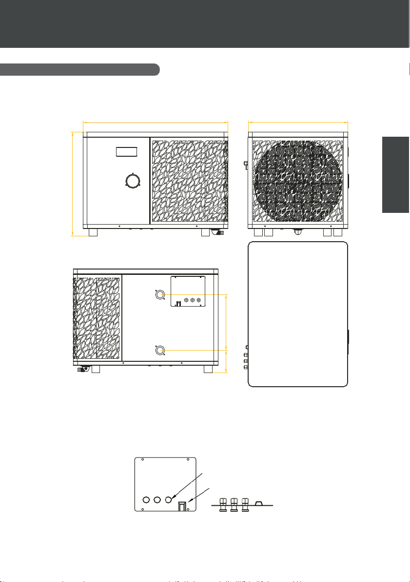
6 | PL
2.OPIS
Wymiaryproduktu
PL
Wymiary w mm
505
705 485
270
Uwaga:Jeśli grzałka elektryczna, pompa wody lub sterownik przewodowy nie są w pełni
podłączone, należy użyć „gumowej zaślepki”, aby uniknąć uszkodzeń spowodowanych wilgocią.
110
Zaślepka gumowa
Pokrywa puszki
przyłączeniowej
Page 97
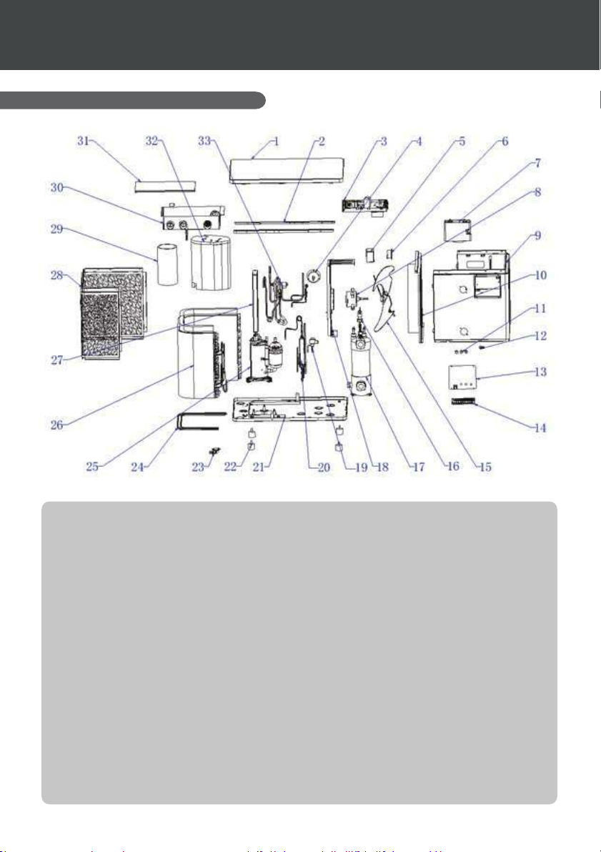
2.OPIS
6 | PL
1. Pokrywa górna
2.6 Widok rozstrzelony
2. Boczne listwy montażowe
3. Komponenty elektryczne
4. Manometr
5. Skrzynka uszczelniająca dławika
6. Dławik / Induktor
7. Wyświetlacz
8. Silnik wentylatora
9. Panel przedni (kompletny)
10. Przegroda centralna (kompletna)
11. Dławnica kablowa / Przepust kablowy
12. Zaciskarka
13. Pokrywa listwy zaciskowej
14. Listwa zaciskowa
15. Wentylator
16. Przełącznik przepływu (Czujnik
przepływu)
17. Tytanowy wymiennik ciepła
18. Wspornik silnika
19. Elektroniczny zawór rozprężny
20. Parownik
21. Elementy podstawy (podwozia)
22. Nóżki antywibracyjne
23. Kolanko odpływowe
24. Kabel grzewczy tacy ociekowej (podstawy)
25. Sprężarka
26. Elementy parownika
27. Wspornik skrzynki elektrycznej
28. Elementy tylnego panelu bocznego
29. Izolacja akustyczna 1 (Wygłuszenie)
30. Skrzynka sterownicza
31. Pokrywa skrzynki sterowniczej
32. Izolacja akustyczna 2 (Wygłuszenie)
33. Zawór 4-drogowy (czójdrożny)
Page 98
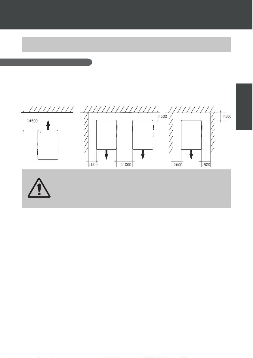
PL | 7
3.MONTAŻ
Lokalizacja
Aby zainstalować pompę ciepła, wystarczy podłączyć jedynie obieg hydrauliczny oraz
zasilanie elektryczne.
PL
Norma NF C 15-100 zaleca, aby pompa ciepła była zainstalowana w odległości co najmniej 2,5
metra od wanny SPA.Jednakże, dzięki zastosowaniu wyłącznika różnicowoprądowego, możliwe
jest zainstalowanie urządzenia bliżej, pod warunkiem zachowania następujących odstępów:należy
pozostawić co najmniej 1,50 m wolnej przestrzeni przed pompą ciepła oraz 30 cm po bokach i z
tyłu urządzenia.
Wymiary w mm
Nie należy umieszczać żadnych przedmiotów w odległości mniejszej niż 1,5 m
od przedniej części pompy ciepła.
Nie blokować przepływu powietrza od góry ani z przodu urządzenia.
Nie używać pompy ciepła jako stopnia do wchodzenia do basenu. Nie stawać na
pompie ciepła.
Podczas wyboru miejsca instalacji pompy ciepła należy przestrzegać następujących
zasad:
1.
Miejsce instalacji musi być łatwo dostępne, aby zapewnić optymalną pracę
urządzenia oraz umożliwić jego konserwację.
2.
Urządzenie należy zamontować na podłożu, najlepiej na płaskiej płycie
betonowej.Upewnij się, że podłoże jest wystarczająco stabilne i wytrzyma ciężar
urządzenia.
3.
Zapewnij odpowiedni przepływ powietrza: upewnij się, że wydmuchiwane powietrze nie
jest skierowane w stronę okien sąsiednich budynków i nie dochodzi do jego recyrkulacji
(powrotu do wlotu powietrza).Ponadto
należy upewnić się, że wokół urządzenia zapewniono wystarczającą przestrzeń do przeprowadzania
konserwacji i napraw.
4.
Urządzenia nie wolno instalować w miejscach, w których mogłoby być narażone na
działanie olejów, gazów łatwopalnych, substancji korozyjnych, związków siarki lub w
pobliżu urządzeń o wysokiej
częstotliwości.
5.
Nie instalować urządzenia w bezpośrednim sąsiedztwie dróg lub chodników, aby uniknąć
zabrudzenia (np. błotem).
6.
Aby nie zakłócać spokoju sąsiadów, urządzenie należy ustawić tak, aby strumień
powietrza (i hałas) był skierowany w stronę przeciwną do stref wrażliwych na hałas.
7.
W miarę możliwości urządzenie powinno znajdować się w miejscu niedostępnym dla dziec i.
Page 99
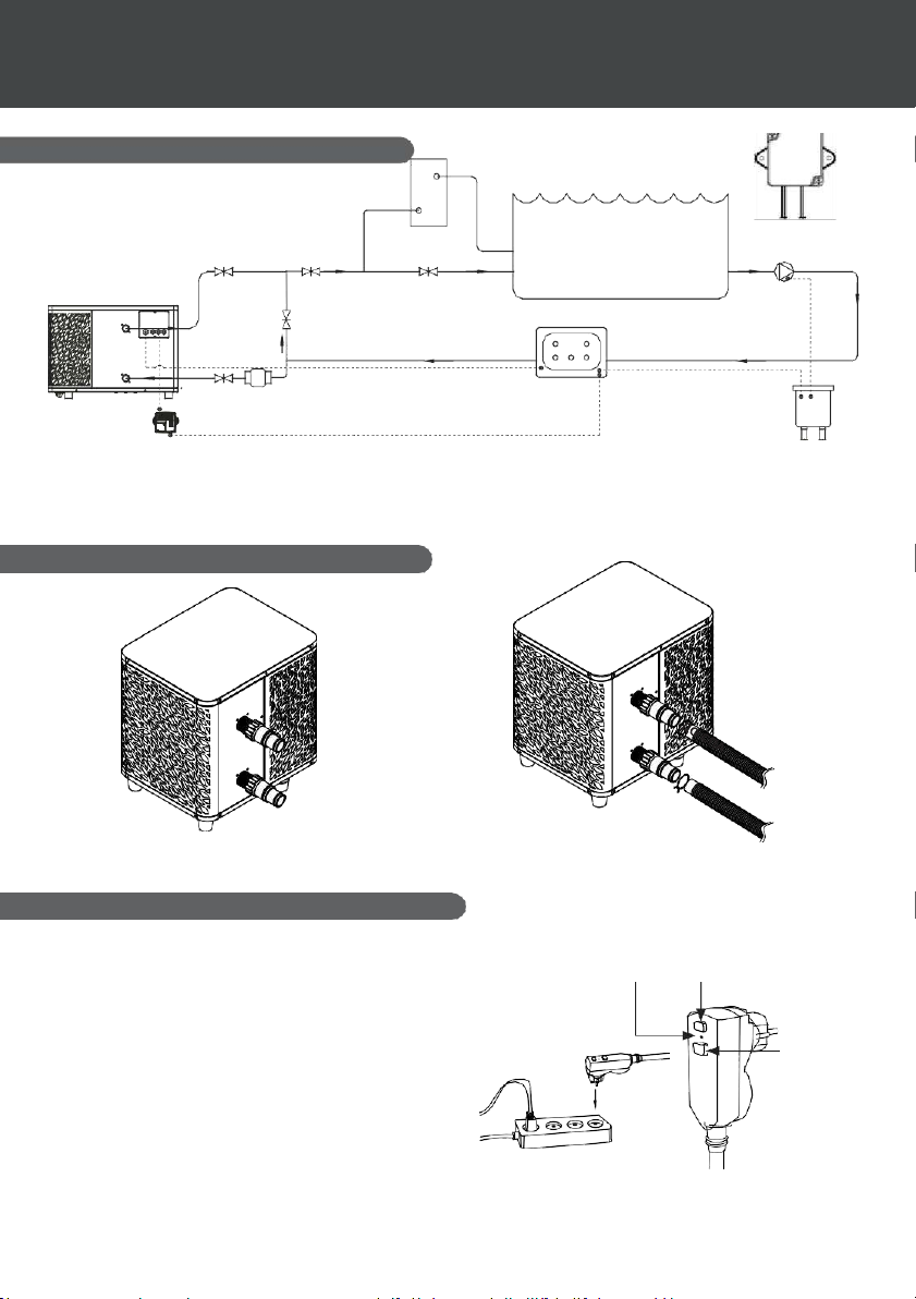
8 | PL
Uwaga: Filtr znajdujący się przed pompą ciepła musi być regularnie czyszczony, aby woda w systemie
3.2
Schemat instalacji
*
Ozon
UV
SPA / BASEN
Slice Valve Slice Valve
Slice Valve
Pompa wody
Zawór bypass
System sterowania SPA z
grzałką elektryczną
Wylot
SPA ICE 70
Wlot Slice Val ve
Zawór regulac ji przep ływu
Sieć elektryczna In Grid
Zasilanie
główne
3.MONTAŻ
Krok 2
3.3 Podłączenie hydrauliczne
Krok 1
pozostawała czysta. Pozwoli to uniknąć problemów eksploatacyjnych związanych z zabrudzeniem lub
zapchaniem filtra.
* Jeśli przekaźnik jest instalowany na zewnątrz, należy go zamontować w taki sposób, aby kabel wyjściowy był
skierowany w dół.
Przykręć złączki do pompy ciepła | Podłącz wlot i wylot wody
Podłączenie elektryczne
3.4
Wtyczka zasilająca pompę posiada wbudowany
wyłącznik różnicowoprądowy (RCD) o prądzie
zadziałania 10 mA.
Należy regularnie sprawdzać jego poprawne
działanie.W przypadku powtarzającego się wyzwalania
wyłącznika lub jakichkolwiek wątpliwości należy
skontaktować się z serwisem.
Przed podłączeniem pompy ciepła należy upewnić się,
że gniazdo elektryczne jest prawidłowo uziemione
oraz zabezpieczone przed deszczem i rozbryzgami
wody.
Naciśnij przycisk RESET, aby uruchomić pompę
ciepła.Wskaźnik zasilania świeci na czerwono:pompa
ciepła jest włączona.
Wskaźnik
zasilania
TES
T
Uruchomienie
Page 100

PL | 9
3.MONTAŻ
Eksploatacja
PL
Warunki użytkowania
Aby zapewnić prawidłowe działanie pompy ciepła, temperatura powietrza otoczenia
musi mieścić się w zakresie od -25°C do 43°C.
Uwagi wstępne
Przed uruchomieniem pompy ciepła należy:
✓ Upewnić się, że urządzenie jest ustawione stabilnie.
✓ Upewnij się, że manometr wskazuje ciśnienie powyżej 80 psi.
✓ Upewnij się, że okablowanie elektryczne jest prawidłowo podłączone do zacisków.
✓ Sprawdź poprawność uziemienia.
✓ Upewnij się, że przyłącza hydrauliczne są szczelne i nie ma wycieków wody.
✓ Upewnij się, że woda krąży w pompie ciepła w sposób prawidłowy, a przepływ
jest wystarczający.
✓ Usuń z otoczenia urządzenia wszystkie niepotrzebne przedmioty oraz narzędzia.
Eksploatacja
1. Podłącz wtyczkę zasilania urządzenia.
2. Uruchom pompę filtrującą.
3. Włącz zabezpieczenie zasilania urządzenia (wyłącznik różnicowoprądowy
znajdujący się na przewodzie zasilającym).
4. Uruchom pompę ciepła.
5. Ustaw żądaną temperaturę, korzystając z jednego z trybów dostępnych na panelu
sterowania.
6. Sprężarka pompy ciepła uruchomi się chwilę po wykonaniu tych czynności.
Teraz wystarczy poczekać na osiągnięcie ustawionej temperatury.
UWAGA: w normalnych warunkach odpowiednio dobrana pompa ciepła może
podgrzać wodę w wannie o 1–2°C na godzinę.Dlatego też brak wyczuwalnej
różnicy temperatury wody na wylocie podczas pracy pompy jest zjawiskiem
całkowicie normalnym.
Ogrzewana wanna powinna być przykryta i zaizolowana, aby uniknąć strat ciepła.
Warto wiedzieć: ponowne uruchomienie po zaniku zasilania
Po zaniku zasilania lub awaryjnym wyłączeniu system zrestartuje się i przejdzie w tryb czuwania
(Standby).Należy zresetować wyłącznik na wtyczce i włączyć pompę ciepła.
 Loading...