

Page 1
user
manual
user
manual
Page 2

PLEASE NOTE:
The Poolrite innoChlor has been designed
to work in both Salt and Mineral Salt pools
index
Introduction 1
Operating Instructions 2
Chlorine Output Control
Manual ON / OFF / AUTO
Fuse Holder
Analogue Timer Setting Procedure 3
Colour Reference Guide 4
Maintenance 5
Pool Chemistry 6
Calculating Pool Volume
Controlling Chlorine Levels
Calculating Salt
Controlling pH
Total Alkalinity
Installation Instructions 8
Power Pack
Cell
Warranty 9
Warranty Exclusions
Rev: 20171020
Page 3
user
manual
Congratulations for purchasing the Poolrite innoChlor salt and mineral salt chlorinator. This
manual has been prepared for the pool owner or pool technician. It includes instructions
for operation, maintenance and installation. We have also included some tips for
maintaining the water chemistry and improving the longevity of the chlorinator and cell.
We trust that this unit will provide many years of reliable service.
The Poolrite innoChlor chlorinator is Australian Made and Owned and has been developed
in Australia, for Australian conditions, with cutting edge technology for a reliable and cost
effective sanitizing system. We specied the highest quality electrodes and polymers
incorporating the latest technology.
1
Page 4
operating instructions
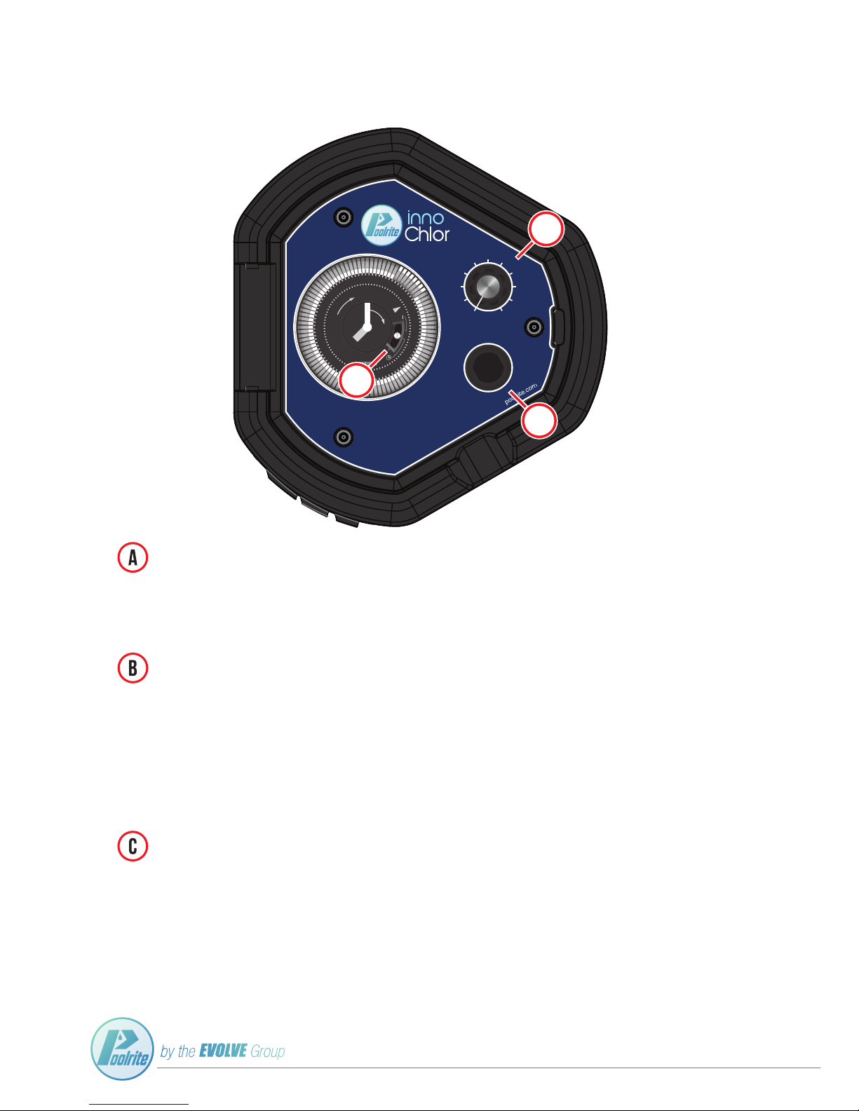
Chlorine Output Control Knob
The innoChlor chlorinator has been tted with a variable chlorine output control. Simply select the exact output
of chlorine for your pool by dialing the control knob. By turning the control knob clockwise, this will increase the
chlorine output and anti-clockwise will lessen the chlorine output to your pool.
Fuse
0
10
C
h
l
o
r
i
n
e
O
u
t
P
u
t
c
o
n
t
r
o
l
ON
Off
AUTO
m
o
d
e
12
6
9
0
2
4
2
3
2
2
2
1
2
0
1
9
1
8
1
7
1
6
1
5
1
4
1
3
1
2
1
1
1
0
9
8
7
6
5
4
3
2
1
Timer Clock: Manual AUTO / OFF / ON
The innoChlor Chlorinator has been tted with a Timer Clock with AUTO / OFF / ON functionality.
ON The upper position will turn on the innoChlor chlorinator indenitely.
AUTO The middle position will set the innoChlor chlorinator to automatic timer mode.
(See Page 3 for Analogue Timer Setting Procedure)
OFF The lower position will turn off the innoChlor chlorinator indenitely.
Fuse
C
h
l
o
r
i
n
e
O
u
t
P
u
t
c
o
n
t
r
o
l
m
o
d
e
12
6
9
0
2
4
2
3
2
2
2
1
2
0
1
9
1
8
1
7
1
6
1
5
1
4
1
3
1
2
1
1
1
0
9
8
7
6
5
4
3
2
1
Fuse Holder
The InnoChlor Chlorinator is tted with a fuse holder.
If the pump is running but there is no LED display lights check to see if the fuse is blown.
If the fuse is blown, replace the fuse to reset the unit.
This will then allow for the unit to run correctly.
If the fuse blows again please consult your local distributor for further details.
0 10
C
h
l
o
r
i
n
e
O
u
t
P
u
t
c
o
n
t
r
o
l
F
U
S
E
Read the Poolrite innoChlor User Guide prior to operation, available at
12
6
9
0
2
4
2
3
2
2
2
1
2
0
1
9
1
8
1
7
1
6
1
5
1
4
1
3
1
2
1
1
1
0
9
8
7
6
5
4
3
2
1
12
6
9 3
0
1
13
2
14
3
15
4
16
5
17
6
18
7
19
8
20
9
21
10
22
11
23
12
24
b
A
C
2
Page 5
user
manual
analogue timer setting procedure
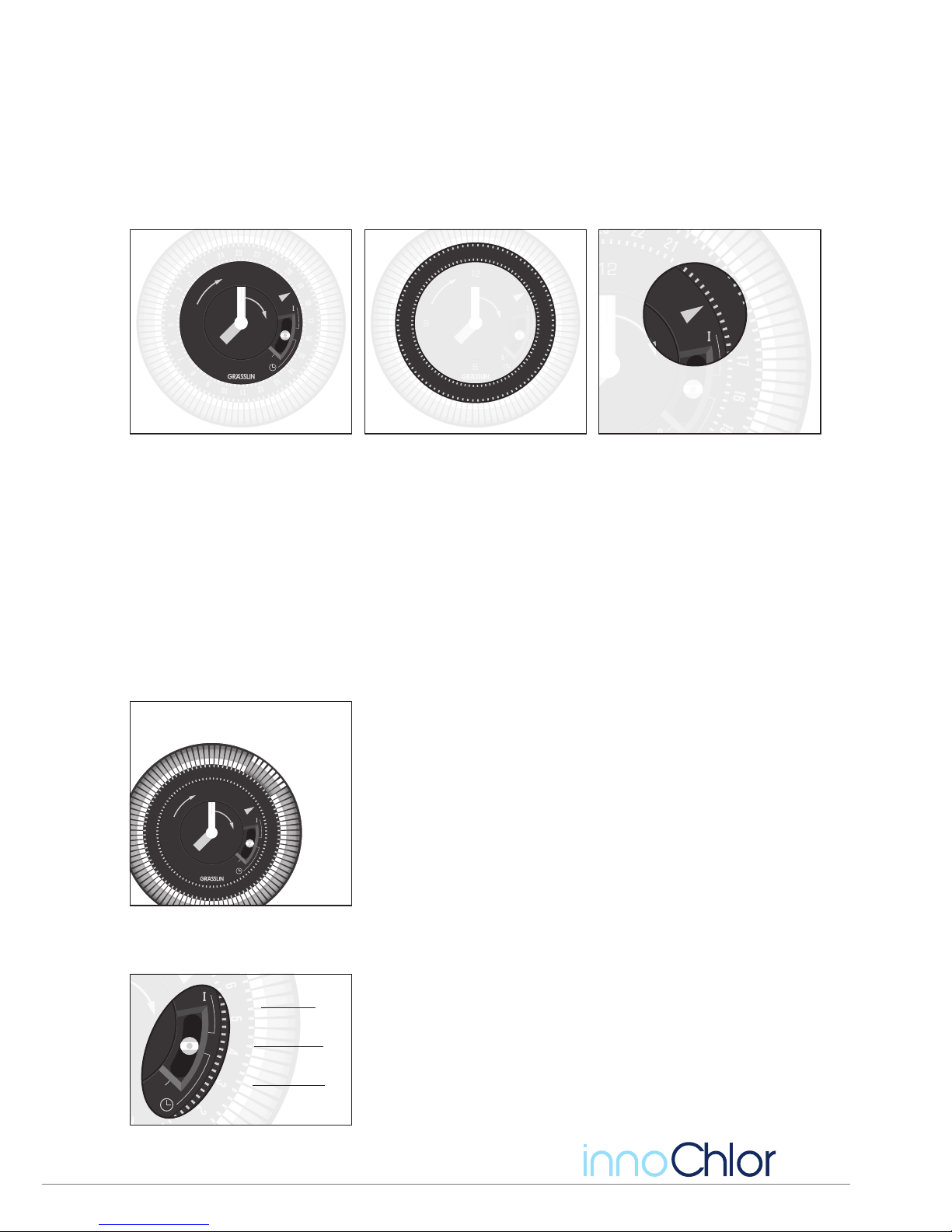
The timer module is equipped with a ratchet mechanism that allows rotation in the clockwise direction.
Attempting to force the dial in the anti-clockwise position can damage the internal gears.
STEP 1 - Set the time
Clasp the outer face of the dial and rotate it clockwise. The internal ratchet will emit a buzzing sound that is
normal. Stop rotating when the correct time is reached. If you overshoot, then continue turning clockwise until
the correct time is reached. 12 hour indication is displayed by an hour hand and a minute hand on the inner dial.
24 hour indication is displayed on the outer dial. The timer depicted indicates 7 on the inner dial and 19 on the
outer dial. Hence the time is set to 7:00pm.
STEP 2 - Set the toggles
The toggles activate the internal switch that turns the unit on and off. These each correspond to 15 minutes of
running and are located around the periphery of the 24 hour dial. When placed on the inner position, the switch
will be off. Sliding the toggle to an outer position will cause it to depress the internal switch and activate the
chlorinator.
The example to the left has eight of the toggles on the outside position.
The timer is set for a time of 7:00am. The toggles from 7:00am to 9:00am
are in the outer position. These will activate the switch when they align
with the 24 hour clock indicator. At 7:00am, the chlorinator and pump will
turn on and at 9:00am, they will turn off.
Set the toggles around the 24 hour face as appropriate. During summer, it
is advisable to run the unit for about 4 hours in the morning and another
4 hours after the sun has gone down. If the swimming pool is tted with
an up sized chlorinator, then it may only need to run 4 to 5 hours daily
depending on organic loadings.
STEP 3 - Set the main switch
The timer is tted with a three position switch. The top position will turn
on the unit indenitely. The middle position is the normal running position
whereby the unit is activated by the toggles. Switching to the bottom
position will turn off the chlorinator indenitely.
For automatic operation, set the switch to the middle position.
12
6
9 3
0
1
13
2
14
3
15
4
16
5
17
6
18
7
19
8
20
9
21
10
22
11
23
12
24
12 hour clock face
3
15
16
17
18
19
20
21
22
24 hour clock indicator
12
6
9 3
0
1
13
2
14
3
15
4
16
5
17
6
18
7
19
8
20
9
21
10
22
11
23
12
24
24 hour clock face
12
6
9 3
0
1
13
2
14
3
15
4
16
5
17
6
18
7
19
8
20
9
21
10
22
11
23
12
24
Toggles are set to turn on at 7:00am until
9:00 am
Toggle
set on
Toggle
set off
3
0
1
2
3
4
5
6
7
8
TOP POSITION
Constantly on
MIDDLE POSITION
Toggle Timer
BOTTOM POSITION
Completely Off
3
Page 6
colour reference guide
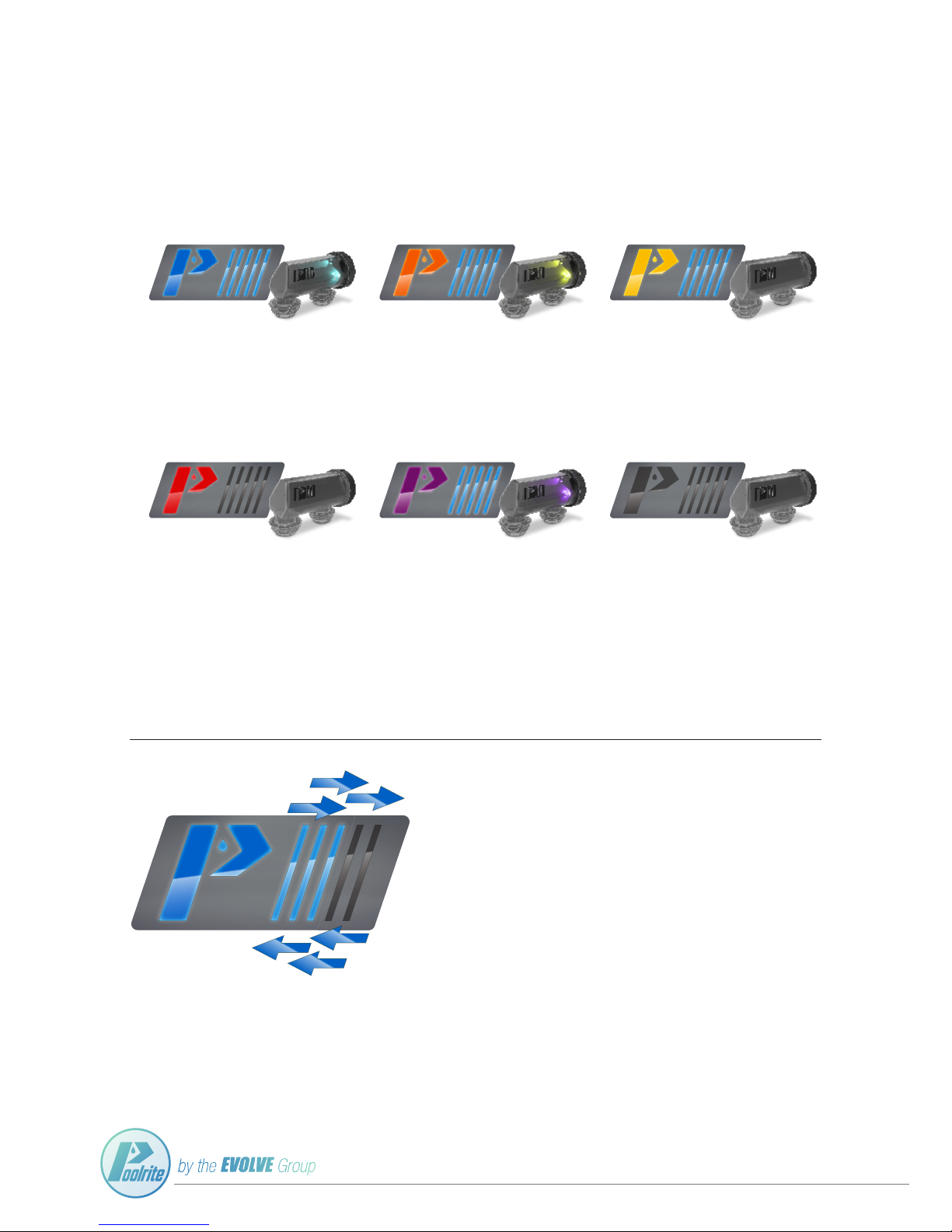
The Poolrite innoChlor salt and mineral salt chlorinator has been made with a self-diagnosing LED display in both
the power pack and cell. The chlorinator will change colours depending on the status and condition of the pool
water, pump ow, chlorinator and/or cell.
LIGHT BLUE
OPTIMAL SALT LEVEL
When the pool salt level is correct
(approx. 3500ppm). The innoChlor colour
LED will shine a blue colour.
ORANGE
LOW SALT
The LED indicator will change to ORANGE
when the salt level falls below the minimum
setting (approx. 1500ppm).
YELLOW
HIGH SALT
The LED indicator will change to YELLOW
when the salt is above the recommended
level (approx. 6500ppm).
RED
EXTREME HIGH SALT
When extreme high salt is detected
(above approx. 8000ppm) the chlorinator will
shut down and attempt to restart after 2
hours. If an extreme high salt alarm persists
after 3 Hours, check and lower your pool salt
concentrate to the recommended level.
PURPLE
NO WATER FLOW
Ensure your pool pump is active, if your pool
pump has unexpectedly stopped priming, shut
down the chlorinator immediately.
BLANK
POWER OUTTAGE
Ensure the innoChlor is receiving power.
4
CHLORINE OUTPUT LED BAR
The Poolrite innoChlor utilises LED lights to assist you in knowing how much you are
increasing, or decreasing the chorine output. By turning the Chlorine Output Control
Knob (see page 2) the ve 'light bars' located on the front of the unit will display what
strength the chlorine output is.
The fewer LED bars = the lower amount of chlorine is being produced.
The more LED bars = the higher amount of chlorine is being produced.
Page 7
user
manual
maintenance
The electrode has been designed for Reverse Polarity cleaning and Velocity cleaning. It is normal for one of the
outside plates to build up a white deposit. This should be removed when the unit changes polarity. The deposit
will then form on the other side.
The amount of deposit will depend mostly on the running time, calcium level in the water and pH level. If the
calcium level in the water is above 250ppm or other metallic contaminants are present, then it may be necessary
to acid wash the electrode periodically.
To acid was the electrode, prepare 1 Litre of dilute acid solution as follows:
Fill 900ml of water into a plastic bucket. Add 100ml of swimming pool grade hydrochloric acid.
Note: Pay attention to the safety precautions when handling acids.
• Disconnect power to the chlorinator.
• Uncouple the two pipe connectors under the electrode. Do not disconnect the electrical lead.
• Invert the electrode assembly and rest it on a at surface.
• Clear any accumulated debris from the plates. Do not scrape the plates.
• Pour the diluted acid into one of the ports until the electrodes and white deposits are completely
immersed.
• Stand for 10 to 15 minutes.
• Discard the solution in the electrode - Do not put it back into the pool.
• If deposits remain, then repeat the process.
• When the electrode is sufciently clean, ush it with fresh water.
• Ret the electrode to the pipe work. Ensure that the O rings are correctly seated, grit free and lubricated
with non-acetic silicon grease.
5
Page 8

pool chemistry
The InnoChlor Chlorinator automatically generates free chlorine from sodium chloride salt. This can be used to
sanitize swimming pools, spa pools or gray water recycling systems. After the chlorine kills algae or bacteria,
it reverts back into salt that will be electrolyzed into chlorine when it passes into the cell again. The salt will be
recycled indenitely however rainwater and fresh water will eventually dilute the salt and more will need to be
added periodically.
CHEMICAL IDEAL LEVELS
Salt 3000 to 4000 ppm
Free Chlorine 1.0 to 3.0 ppm
PH 7.2 to 7.6
Cyanuric Acid 60 to 80 ppm
Total Alkalinity 80 to 120 ppm
Calcium hardness Max 300 ppm
Metals 0 ppm
Saturation Index -0.2 to 0.2
Calculating Pool Volume
For square and rectangular pools
Volume = Length x Width x Average Depth x 1000 Liters.
For Oval, round and kidney shapes
Volume = Length x Width x Average Depth x 850 Liters.
Controlling Chlorine Levels
When rst installing the equipment, check the chlorine level daily. Set the output to maximum and reduce the
running hours if the chlorine level exceeds 3ppm. Increase the running hours if the chlorine level is below 1ppm.
When the daily results are consistent, change the testing frequency to weekly. If the testing is consistent, then
longer test periods may be used.
Notes:
• A high pH will reduce the amount of free chlorine and require excessive running of the chlorinator and
pump. Correctly maintained pH will reduce electricity demand and prolong electrode life.
• Sunlight will destroy free chlorine. Cyanuric acid will protect the free chlorine from sunlight.
• Excessive organic material such as plant leaves and dirt will consume chlorine.
• A correct chemical balance and a clean pool will use less electricity and prolong the electrode life.
Calculating Salt
Only use swimming pool grade sodium chloride salt (NaCl). The innoChlor will automatically adjust the output to
suit the salt level in the water. An incorrect salt level will cause premature failure of the electrode.
Salt Quantity (kg) = Pool Volume (Liters) x Salt concentration (ppm)
1,000,000
Example: A 60,000 liter pool requiring 3000ppm salt will need 180 kg of salt added.
6
Page 9
user
manual
pool chemistry
Controlling pH
NOTE: At a pH of 8 only 25% of your chlorine will be an effective sanitizer. It will get worse as pH
increases - at a pH pf 8.5, less than 10% of your chlorine is active. The other 90% is completely
wasted. Keeping your pH between 7.2 and 7.5 maximizes the power of the chlorine and makes the pool
comfortable.
The pH is a measure of acidity of pool water. A pH less than 7.0 is acidic, a pH of 7.2 is neutral and a pH greater
than 7.6 is alkali. The operation of the chlorinator tends to remove hydrogen from the water and hence pH will
trend upwards. It is likely that acid and buffer will need to be added periodically. Failure to do so will cause
uncomfortable stinging in eyes, excessive scaling of the electrodes and heavy demand on chlorine. This in turn
will cause excessive running of the equipment and needless cost.
To decrease pH, add water to a bucket then dilute 1 part swimming pool hydrochloric acid for 2 parts water. Add
the mixture to the pool water. Use a test kit to determine the amount of acid to add.
To increase pH, add sodium bi-carbonate
Total Alkalinity
Total alkalinity is a measure of the buffer that will resist changes to the pH. A high TA will assist with maintaining
the correct pH level. Add pH buffer to increase or acid to decrease.
specifications
INPUT 240V / 50Hz
POWER CONSUMPTION 250 VA
OUTPUT
Pump Socket 240V 50Hz
1.5Kw (2.0HP)
8.5A
Cell Refer Table
FUSE 1.6A Slow-Blow Fuse (Size: 5mm x 20mm)
IP RATING 24
CLASS I
TYPE Y
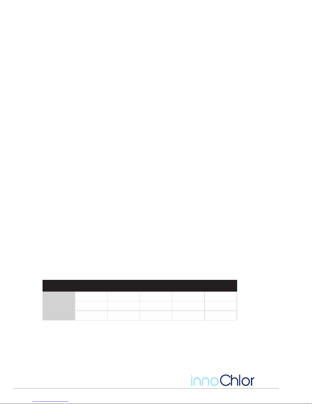
Model Cl Output Cell Endurance
Cell
Current
Cell
Voltage
Salt
InnoChlor P15 15 10,000 Hours 7A 15 3500 ppm
InnoChlor P25 25 10,000 Hours 11A 15 3500 ppm
InnoChlor P35 35 10,000 Hours 16.5A 15 3500 ppm
7
Page 10

installation instructions
Power Pack
1) Mount the power pack horizontally against a wall or at surface of at least 350 x 350 mm size.
2) For a timber wall, drill two 3mm diameter holes horizontally 60 mm apart. Fit the mounting bracket and
screws into the holes.
3) For a masonry wall, drill two 5mm diameter holes horizontally 60 mm apart. Fit the Rohr plugs then screws.
4) Plug the pump into the socket outlet at the side of the unit.
5) Hang the power pack from the mounting bracket.
6) Plug the power pack into an approved 10 amp 240V socket outlet.
7) The power pack is rated for IP24 and may be installed in the pool zone.
8) Ensure that the installation complies with the requirements of the AS/NZS 3000 wiring rules.
WARNING:
Do not mount the unit in direct sunlight.
Do not mount the unit in a manner that will restrict air- ow around the heatsink (back plate).
Ensure that the unit is mounted at least 1 meter from the ground and not subject to ooding.
Do not allow the unit to operate lying down. This can cause overheating.
Do not plug in a pump(s) that draws more than 8.5 amps.
Do not use extension leads to supply power to the unit or between the unit and the pump.
Do not mount the unit above heat sources such as gas heaters.
Please refer to warranty exclusions for non-compliance
Off-Peak Installations
This unit is suitable for connection to an off-peak tariff supply.
CELL
The cell is connected to the power pack via a 1.5 meter lead.
Connect the cell into the return pipe work to the pool.
Multiple electrodes should be connected in parallel. Series connection will cause premature failure of the downstream electrode.
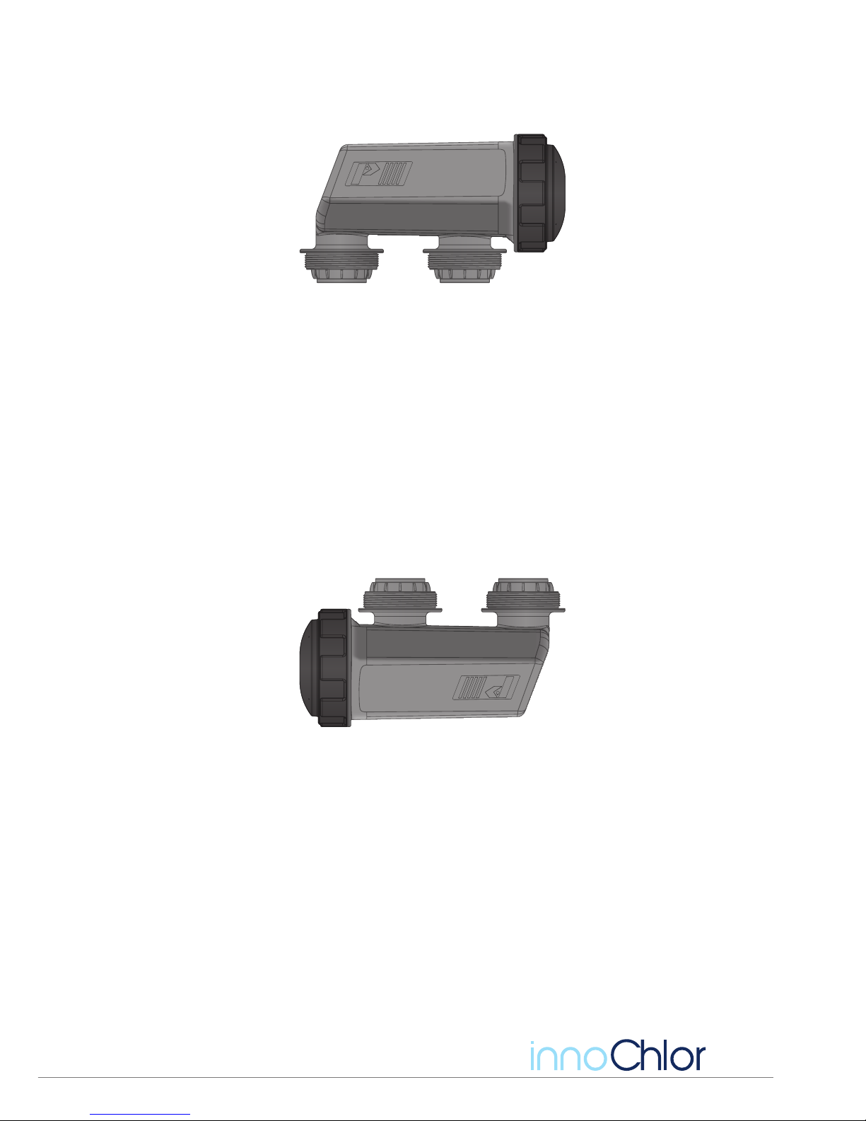
Install the cell horizontally with the two ports oriented downwards. Cell must be installed within 5º/-5º of level.
The water can ow in only one direction through the cell. It must enter at the cell cap end.
Heaters and other equipment in the return to pool line must be before the cell i.e. between the cell and lter.
TIP: When specifying a chlorinator size, in moderately warm climates, 1 gram per hour output per 2500 Litres of
swimming pool capacity is recommended.
If the pool usage is heavy, and the climate is hot, then salt levels should be at the maximum in order to boost
chlorine output.
Water features and disappearing edge pools can loose excessive amounts of chlorine. In these cases, size the
chlorinator capacity as 2 grams per hour output per 2500 Litres of swimming pool capacity.
8
Page 11

user
manual
warranty
The warranty is a 2 year full replacement warranty on the power pack.
The Cell is a 3 year full replacement warranty, plus a further 24 month pro-rata on the electrode.
Evolve Group warrants the chlorinator to be free from defects in material or workmanship, under normal use and service on private,
single-family residential swimming pools or spas within Australia and New Zealand for two years or 5000 hours operation whichever is
rst, from date of the initial system installation, provided it is installed in accordance with the installation instructions and specications. If
written proof of the date of the initial system installation is not provided to Evolve Group, the manufactured date will be the sole determinant of the date of the initial system installation.
If a product is defective, in workmanship or materials and is removed within 2 years (24 months) after the date of the initial system installation and is returned freight prepaid, Evolve Group will, at it’s option, either repair or replace the defective product and return it freight
prepaid. For years 4 and 5, Evolve Group will, at it’s option, either repair or replace the defective cell and will charge 60% for the 4th year
and 40% for the 5th year off the current list price for such repairs or replacements, plus shipping charges. Evolve Group will not assume
any of the cost incurred in removal or re-installation of the product.
This Limited Warranty does not apply to installations in commercial pools, public pools, and pools located outside Australia and New
Zealand.
Replacement parts
If a purchased replacement part is defective, in workmanship or materials and is removed within 1 year (12 months) after the date of
purchase, and is returned freight prepaid, Evolve Group will, at it’s option, either repair or replace the defective purchased part and return
it freight prepaid.
Warranty Exclusions
Commercial pools, public pools and pools located outside Australia and New Zealand
Incorrect mounting of the power pack or electrode including but not limited to:
• Power pack mounted in direct sunlight.
• Restricted air- ow around the heat sink (back plate).
• Mounted within 1 meter of the ground or subject to ooding.
• Operated lying down.
• Oversized pump or pumps installed. I.e. current draw of more than 8.5 amps.
• Use of extension leads to supply power to the unit or between the unit and the pump.
• Mounted above a heat sources such as a gas heater.
• Mounted above chemicals, or within range of chemical vapour.
Incorrect salt level or water balance
Poor water ow
Excessive scaling
Excessive acid washing or washing in concentrated acid solutions.
Electrode damage due to mechanical cleaning
Loose cell terminal connection
Excessive use of algaecides
Unltered water entering the cell
Metallic contaminants from the water
Consequential damage caused by the failure of other equipment in the pool installation
Blown fuse
Vermin/insect infestation
Water or dust contamination in the power pack
Damage due to causes beyond the control of Evolve Group
Leaks due to incorrect tting.
Damage caused by static pressure in excess of 200 kPa
Material supplied or workmanship performed by others in the process of installation
Problems resulting from failure to operate the products in accordance with recommended instructions
Problems resulting from failure to maintain pool water chemistry in accordance with recommended levels.
Problems resulting from inadequate chlorine output outside of the recommended sizing
Problems resulting from tampering, accident, abuse, negligence, unauthorized repairs or alterations,
re, ood, lightning, freezing, external water, war, or acts of God.
The express warranty above constitutes the entire warranty of Evolve Group with respect to the chlorinator products and is in lieu of all oth-
er warranties, expressed or implied, including a warranty of tness for a particular purpose. In no event shall Evolve Group be responsible
for any consequential or incidental damages of any nature whatsoever.
No wholesaler, agent, dealer, contractor, or other person is authorized to give any warranty on behalf of Evolve Group. This warranty is void
if the product has been altered in any way after leaving the factory.
9
Page 12

group
Poolrite is an Australian made and owned
product of the Evolve Group of companies
 Loading...