

Pool Pro Neptune Series, Neptune NDC25, Neptune NDC35, Neptune NDC45, Neptune NDC55 Installation & Operating Manual
...Page 1
Page 2

Congratulations on your recent purchase of your new Neptune Digital Salt Water
Chlorinator. Thank you for supporting Pool Pro Products. Please read this manual
carefully before installing, maintaining or troubleshooting your Neptune Digital Salt
Water Chlorinator.
While every effort has been made to ensure that the information contained in this guide
is accurate and complete, no liability can be accepted for any errors or omissions. Pool
Pro reserves the right to change the specications described herein at any time without
prior notice.
CONTENTS
Warnings & Safety Instructions ............................................................ Page 3
Packaging Contents ............................................................................. Page 4
Tools Needed ........................................................................................ Page 4
Installation Diagram .............................................................................. Page 4
Preparing the Pool ................................................................................ Page 5
Installing the Cell .................................................................................. Page 5
Installing the Chlorinator Power Pack ................................................... Page 5
Water Balancing ................................................................................... Page 6
Control Panel Operation ....................................................................... Page 7
Initial Start-up ....................................................................................... Page 8
The Main Screen .................................................................................. Page 9
Main Menu ............................................................................................ Page 9
Backwash ............................................................................................. Page 9-10
Brightness ............................................................................................. Page 10
Cell Cleaning ........................................................................................ Page 10
Chlor Boost ........................................................................................... Page 11
Chlor Setting ......................................................................................... Page 11
Clock/Timer .......................................................................................... Page 11-12
Contrast ................................................................................................ Page 13
Power/Mode ......................................................................................... Page 13
Pump Setting ........................................................................................ Page 13
Salt Test ................................................................................................ Page 13-14
Service Menu ........................................................................................ Page 14
Spa Mode ............................................................................................. Page 14
Winter Mode ......................................................................................... Page 14
Maintenance ......................................................................................... Page 15
Troubleshooting .................................................................................... Page 16-18
Schematics ........................................................................................... Page 19-21
Chlorine Production Specications ....................................................... Page 21
Technical Support ................................................................................. Page 22
Warranty ............................................................................................... Page 22-23
Page 2 www.poolpro.com.au
Page 3

WARNINGS
This manual contains important information about the installation,
operation and safe use of this product, and should be given to the
owner and/or operator of this equipment. When installing and using
this electrical equipment, basic safety precautions should always
be followed. Failure to follow safety warnings and instructions in
this manual can result in serious injury and/or damage to your
equipment. Read and follow all warnings and instructions.
● The power supply internally contains live electrical components. There is a danger
of electric shock if opened.
● If the carton or product has been damaged or is wet: do not install the product,
contact your Pool Pro stockist.
● The product must be installed in accordance with AS/NZS 3000 Wiring Standards
and must be installed at least 3.5m away from the pool.
● CHLORINE GAS BUILDUP CAN OCCUR WITH IMPROPER WIRING: To reduce
the risk of personal injury, the power pack is designed so that the electrolytic cell
will only receive power when the pool pump is on. Otherwise, dangerous chlorine
gas build-up can occur. If the pump is not installed to the AC Socket (pump outlet)
on the power pack then the installer must ensure that the electrolytic cell is never
energised when the pool pump is OFF or water is not owing through the unit. A
venturi pipe is installed within the cell housing to eliminate any possible gas build
up, however it is RECOMMENDED that the cell housing be installed horizontally to
create a natural gas trap that acts as a safety device. Installation in any other way
may cause explosion, injury or death if the installer does not allow for gas removal.
● If you perform a backwash manually (without using the Backwash function on the
chlorinator) you must turn the chlorinator’s output down to the lowest percentage
setting via the “Chlor Setting” function.
● The pump rating must not exceed 8amps.
● Salt water may damage electrical components in the power pack.
● We DO NOT recommend the use of valves on the inlet or outlet of the cell housing.
If you do use a valve it is important that the valve cannot deadhead (lock closed)
while the pump is running. It is the installer’s responsibility to ensure some form of
ow control is installed in this instance and it disables the pump.
● Ideal salt levels range between 3000-3500ppm (parts per million). Salt levels
below 3000ppm and above 4000ppm may damage equipment and void any
warranty.
● Do not permit children, or persons with reduced physical, sensory or mental
capabilities to use or perform maintenance on this product. To reduce the risk of
accidents or incidents, service on the unit should only be performed by your local
Pool Pro Professional.
Page 3www.poolpro.com.au
Page 4

PACKAGING CONTENTS
Wall
mounting
bracket
Drill with
6mm drill bit
Power
pack
Cell housing with
unions
TOOLS NEEDED
Basic PVC
ttings
Hacksaw PVC primer
INSTALLATION DIAGRAM
2 x 50/40
reducing
bushes
2 x green
wall plugs
with screws
& glue
User
manual
No.2
Phillips head
screwdriver
Page 4 www.poolpro.com.au
Page 5

PREPARING THE POOL
Have your pool water tested by your local Pool Pro Professional. Ideal salt levels
range between 3000-3500ppm (parts per million). Salt levels below 3000ppm and
above 4000ppm may damage equipment and void any warranty.
For new pool installations, consult your pool builder or your local Pool Pro Professional
before adding salt. Some pool builders do not recommend the addition of salt for a
period of time following completion of the swimming pool.
Use Pool Pro Ultrane Pool Salt or Pool Pro Premium Pool Salt at the rate of 3.5kg
per 1000L of pool water. Mineral/magnesium chloride salts can also be used, including
Neptune Mineral Salt. Add 20%-30% extra product for mineral/magnesium salts.
Add salt to the shallow end of the pool. Use a pool brush to completely dissolve the
salt. Run the pool pump in the rst 8-12 hours to also help dissolve the salt.
NOTE: Never add salt/minerals directly to the skimmer box. High concentrations
of salt/minerals passing through pool equipment may cause damage. Remove
automatic pool cleaner from the pool before adding salt or other chemicals.
INSTALLING THE CELL
Check the O-Ring is installed in the cell housing and use a silicone based lubricant
(do not use petroleum based lubricants). It is recommended that the cell is installed
horizontally and the direction of water ow through the cell housing is entering from the
closed end of the cell housing and exiting from the end closest to the cell locking ring
(to reduce water hammer). Use pressure PVC solvent cement to glue cell unions to the
pipework. The cell must be installed so it is the last piece of equipment in the return line
to the pool.
A shut-off valve on the inlet or outlet of the cell housing is NOT recommended. If a
valve is required, it is recommended to install a non-return valve.
INSTALLING THE CHLORINATOR POWER PACK
The power pack must be installed outside of the pool zone, no more than 1.5m from
the cell, at least 1m above ground, away from chemicals and fertilisers (fumes may
damage the power pack) and in accordance with AS/NZS 3000 Wiring Standards.
Mount the power pack with the mounting bracket, green plugs and screws provided,
in a well ventilated position away from direct sunlight and rain (not in a closed
unventilated shed). If mounting on a post, install a waterproof non-metal at panel as a
backing plate.
Connect the lead from the cell electrode to the cell plug under the power pack, ensuring
a rm snap lock connection.
Plug the power pack into a 3 pin 10Amp weatherproof, RCD (Residual Current Device)
protected socket as per the AS/NZS 3000 Wiring Standards. Plug pump into the AC
socket at the bottom of the power pack.
Page 5www.poolpro.com.au
Page 6
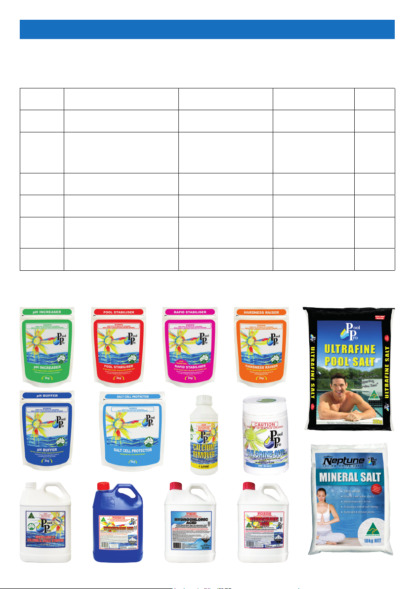
RECOMMENDED WATER BALANCING
Consult your local Pool Pro Professional to correctly balance your pool water. Follow
instructions on the packaging of each chemical. Always add chemicals to water, never
add water to chemicals.
Recommended Values To Increase Value To Decrease Value
pH
Free
Chlorine
T.A. (Total
Alkalinity)
Calcium
Hardness
Stabiliser 30 – 60ppm
Salt 3000 – 3500ppm
This is a guide only, does not constitute and should not be used as an alternative to specic professional
advice. Pool Pro and The POPS Group Pty Ltd accept no liability for any damage, loss or harm associated
with the use of this guide.
Concrete: 7.2 – 7.6 Fibreglass/
Vinyl: 7.0 – 7.2
1 – 3ppm
Concrete: 80 – 150ppm
Fibreglass/Vinyl: 80 – 120ppm
Concrete: 250 – 300ppm
Fibreglass/Vinyl: 150 – 200ppm
Add Pool Pro pH
Increaser (Soda Ash)
Increase the chlorine
output on the chlorinator
unit
Add Pool Pro pH Buffer
Add Pool Pro Hardness
Raiser
Add Pool Pro Stabiliser or
Pool Pro Rapid Stabiliser
Add Pool Pro Ultrane or
Premium Pool Salt
Add Pool Pro
Hydrochloric Acid
Add Pool Pro Chlorine
Out and decrease the
chlorine output on the
chlorinator unit
Add Pool Pro
Hydrochloric Acid
Add Pool Pro Calcium
Remover
Contact your Pool
Pro Professional for
advice
Partially empty the
pool and rell it
Test
Frequency
Weekly
Weekly
Fortnightly
Fortnightly
Fortnightly
Fortnightly
Page 6 www.poolpro.com.au
Page 7

CONTROL PANEL OPERATION
BUTTON FUNCTION
Sets the chlorinator’s operating mode between AUTO, ON and OFF.
This is displayed on the LCD screen next to “Mode”.
Sets the chlorinator and pump to operate for 8 hours at 100% output.
Defaults to 8 hours but can be modied.
Reduces the chlorine output to 50%. Defaults to 50% but can be modied.
Sets the clock (time of day) and the timer (chlorinator operating times).
Measures the salt level of the pool water. Also shows the salt value.
Runs a backwash process to clean the media inside the pool lter system.
- Enters the Main Menu if pressed when the LCD screen is displaying the
Main Screen (see section “Main Screen” on page 9).
- Saves any changes made to the settings.
- Scrolls up any menus.
- Adjusts values of any options selected.
- Scrolls down any menus.
- Adjusts values of any options selected.
- Exits menus.
- Returns to the previous screen.
Used during service by qualied Pool Pro Professionals.
Page 7www.poolpro.com.au
Page 8
INITIAL START-UP
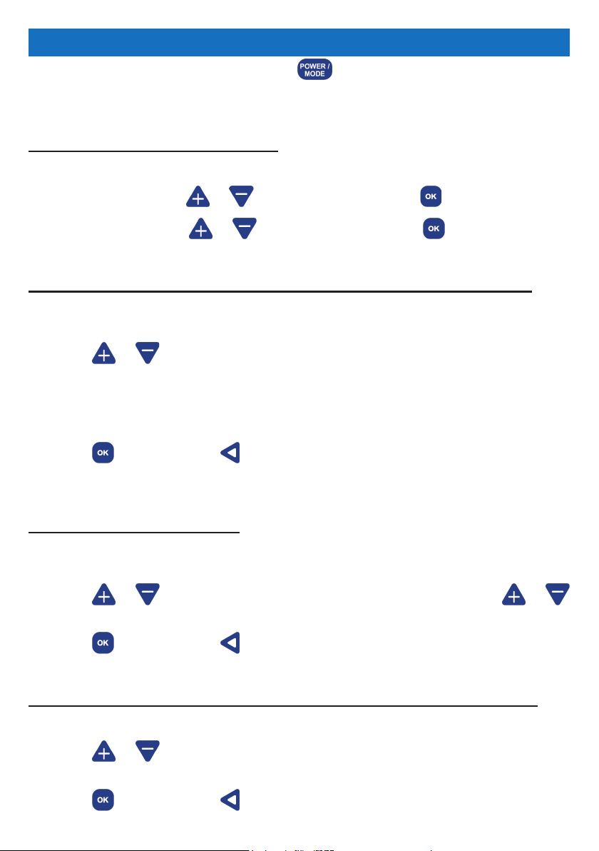
Turn on the chlorinator unit by pressing the button. Wait for the chlorinator unit to
run through a start-up sequence.
SETTING THE CLOCK (time of day)
1. “START UP CLOCK SET” will display on the LCD screen.
2. “HH” will ash. Press or to change the hour. Press to save.
3. “MM” will ash. Press or to change the hour. Press to save.
SETTING THE TIMER / RUN PERIOD (daily run times of the chlorinator)
1. “START UP RUN PERIODS” will display on the LCD screen. “2 CYCLES/DAY” will
ash.
2. Press or to scroll through the cycles.
Select from the following cycles for your chlorinator to operate:
(a) “2 CYCLES/DAY” = 6am - 10am and 4pm - 8pm
(b) “1 CYCLE AM” = 8am - 4pm
(c) “1 CYCLE PM” = 8pm - 4am
3. Press to save or press to exit without saving. If these cycle times are not
suitable, you can change them in the Clock/Timer function – see page 11-12.
SETTING UP THE POOL SIZE
1. “START UP INFORMATION” will display on the LCD screen. The litre quantity for
“POOL SIZE” will ash.
2. Press or to change the litre quantity by 1,000L increments, hold or
to change the litre quantity by 5,000L increments.
3. Press to save or press to exit without saving.
SETTING UP THE MINERAL TYPE (if your pool uses salt or mineral mix)
1. “START UP INFORMATION” will display on the LCD screen. “SALT” will ash.
2. Press or to change the type of mineral used in the pool water. Select from
“SALT” or “MINERAL MIX”.
3. Press to save or press to exit without saving.
Page 8 www.poolpro.com.au
Page 9
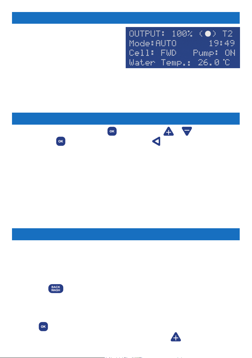
THE MAIN SCREEN
The Main Screen displays the current
settings for the chlorinator.
Output = The output percentage.
(●) symbol = Normal operation.
T1 or T2 = “Single Timer Cycle” or “Dual
Timer Cycle” is selected.
Mode = ON, OFF or AUTO.
HH:MM = The time of day in 24 hour format.
Cell = Cell status (FWD, REV or OFF).
Pump = The status of the pool pump AC socket (ON or OFF).
Water Temp = Pool water’s temperature.
MAIN MENU
To access the main menu, press the button and press or to scroll through
the menu. Press
no activity for more than 60 seconds in any screen, you will be taken back to the Main
Screen. All menu items are:
1 Backwash
2 Brightness
3 Cell Cleaning
4 Chlor Boost
5 Chlor Setting
Some of the menu items have shortcut buttons on the touchpad, allowing quick access
without going through the main menu. The shortcut buttons are Chlor Boost, Winter
Mode, Clock/Timer, Salt Test and Back Wash.
to select a menu option or press to exit the screen. If there is
6 Clock/Timer
7 Contrast
8 Power/Mode
9 Pump Setting
10 Salt Test
11 Service Menu
12 Spa Mode
13 Winter Mode
BACKWASH
This function runs a backwash process to clean the media inside the pool lter system.
IMPORTANT: Never operate the lter’s multi-port valve lever while the pump is
running, as it may cause damage and leaking. The pump will start and stop as
you require. Ensure all valves, valve handles, lids, baskets etc are in the correct
positions as per the requirements of the manufacturer of the equipment.
1. Press the shortcut button or enter Backwash via the Main Menu. The LCD
screen will display “BACKWASH MODE”.
2. Rotate the lter’s multi-port valve lever to the ‘Backwash’ position and ensure the
handle locks in place. This step is not applicable for cartridge lters.
3. Press to begin the backwash cycle. The pump will start and run for 2 minutes.
A countdown timer will display on the LCD screen. Press to increase the run
Page 9www.poolpro.com.au
Page 10
time if desired (up to 3 minutes). If you need to stop the pump during the cycle,
press
4. When the cycle has nished the pump will stop. Ensure the water in the lter’s sight
glass is clear, then press
5. Rotate the lter’s multi-port valve lever to the ‘Rinse’ position and ensure the handle
locks in place. This step is not applicable for cartridge lters.
6. Press to begin the rinse cycle. The pump will start and run for 1 minute.
A countdown timer will display on the LCD screen. Press to increase the run
time if desired (up to 3 minutes). If you need to stop the pump during the cycle,
press
7. When the cycle has nished the pump will stop. Ensure the water in the lter’s
sight glass is clear, then press
COMPLETED”.
8. Rotate the lter’s multi-port valve lever to the ‘Filter’ position and ensure the handle
locks in place. This step is not applicable for cartridge lters.
9. Press to conrm the lter’s multi-port valve lever is set to the ‘Filter’ position.
10. The LCD screen will display “Final check on all valves/lid positions”. Check all other
valves and lids on all equipment are in the correct position. Press the
button to nish the cycle and return to the Main Screen.
to stop the pump immediately. Press to start the pump again.
. The LCD screen will display “RINSE MODE”.
to stop the pump immediately. Press to start the pump again.
. The LCD screen will display “BACKWASH
shortcut
BRIGHTNESS
This function adjusts the brightness of the LCD screen.
1. Press the button to enter the Main Menu. Press or to scroll through the
menu. Press
2. Press or to adjust the brightness.
3. Press to save or press to exit without saving.
to select Brightness.
CELL CLEANING
This function helps to clean calcium build-up that can occur on the cell plates.
1. Press the button to enter the Main Menu. Press or to scroll through the
menu. Press
2. Press or to adjust the frequency of the cell’s cleaning cycle.
3. Press to save or press to exit without saving.
Page 10 www.poolpro.com.au
to select Cell Cleaning.
Page 11
CHLOR BOOST
This function sets the chlorinator and pump to operate for 8 hours at 100% output,
known as Chlor Boost or Superchlorination (extra sanitising time).
1. Press the shortcut button or enter Chlor Boost via the Main Menu.
2. The cycle will automatically begin and run for 8 hours by default.
3. Press or to adjust the run time. You cannot use any other functions while
the Chlor Boost function is running.
4. Press to stop the cycle if needed, otherwise the chlorinator will revert back to
normal settings once the cycle has nished.
CHLOR SETTING
This function controls the chlorine output of the chlorinator. Used for running the pump
for longer hours (i.e. with a variable speed pump or for additional ltration).
1. Press the button to enter the Main Menu. Press or to scroll through the
menu. Press
2. Press or to adjust the chlorine output percentage.
3. Press to save or press to exit without saving.
to select Chlor Setting.
CLOCK/TIMER
This function changes the time of day (clock) and the chlorinator run times (timer).
CLOCK SETTINGS:
1. Press the shortcut button or enter Clock/Timer via the Main Menu.
2. Press the shortcut button again. “CLOCK SETTING” will be displayed on the
LCD screen.
3. The hours will ash. Press or to adjust the hour. Press to save.
4. The minutes will ash. Press or to adjust the minutes.
5. Press to save or press to go back to the hours. Press again to exit
without saving.
TIMER SETTINGS:
Select a timer cycle and then program the times for the cycle/s. For maximum efciency
set the cycle times to run early morning and evening. To run the chlorinator in the “ON”
power mode and override the internal timers, leave all timer settings as 00:00.
Page 11www.poolpro.com.au
Page 12
Ideal Summer settings: 6am - 10am and 4pm - 10pm (less hours for small pools,
more hours for extreme weather). Ideal Winter settings: See Winter Mode on page 14.
1. Press the shortcut button or enter Clock/Timer via the Main Menu.
2. Press to change between SINGLE CYCLE (chlorinator runs once per day) or
DUAL CYCLE (chlorinator runs twice per day).
3. Press to save the timer cycle and enter the timer program.
4. To set the ON/START time for TIMER 1:
“TIMER 1: ON TIME” will display on the LCD screen. The hours will ash on the
LCD screen. Press
will ash. Press
to Step 5, or press
or to adjust the hour. Press to save. The minutes
or to adjust the minutes. Press to save and continue
to go back to the hours and repeat Step 4. Press again
to exit without saving.
5. To set the OFF/STOP time for TIMER 1:
“TIMER 1: OFF TIME” will display on the LCD screen. The hours will ash on the
LCD screen. Press
will ash. Press
to Step 6, or press
or to adjust the hour. Press to save. The minutes
or to adjust the minutes. Press to save and continue
to go back to the hours and repeat Step 5. Press again
to exit without saving.
6. If you chose SINGLE CYCLE, you will be taken back to the Main Screen.
If you chose DUAL CYCLE, continue to the next step.
7. To set the ON/START time for TIMER 2:
“TIMER 2: ON TIME” will display on the LCD screen. The hours will ash on the
LCD screen. Press
will ash. Press
to Step 8, or press
or to adjust the hour. Press to save. The minutes
or to adjust the minutes. Press to save and continue
to go back to the hours and repeat Step 7. Press again
to exit without saving.
8. To set the OFF/STOP time for TIMER 2:
“TIMER 2: OFF TIME” will display on the LCD screen. The hours will ash on the
LCD screen. Press
will ash. Press
the Main Screen or press
or to adjust the hour. Press to save. The minutes
or to adjust the minutes. Press to save and return to
to go back to the hours and repeat Step 8. Press
again to exit without saving.
Page 12 www.poolpro.com.au
Page 13
CONTRAST
This function adjusts the contrast of the LCD screen.
1. Press the button to enter the Main Menu. Press or to scroll through the
menu. Press
2. Press or to adjust the contrast.
3. Press to save or press to exit without saving.
to select Contrast.
POWER/MODE
This function changes the operating mode of the chlorinator. Auto = running on the
timer settings. On = manually running, not using the timer settings. Off = Not running
manually or on the timer settings.
1. Press the button to change between AUTO, ON and OFF.
2. The mode can also be accessed via the main menu. Press the button to enter
the Main Menu. Press
Power/Mode.
3. Press or to adjust the power/mode.
4. Press to save or press to exit without saving.
or to scroll through the menu. Press to select
PUMP SETTING
This function protects the pool pump if there is no water ow. It adjusts the time that the
pump runs after the cell has detected that there is no water ow.
1. Press the button to enter the Main Menu. Press or to scroll through the
menu. Press
2. Press or to adjust the off time of the pump (3-10 minutes). The “OFF”
option disables this feature so the pump will NOT be turned off when there is no
water ow. The “OFF” option is ideal for pools with a ow switch or an external
pump control.
3. Press to save or press to exit without saving.
to select Pump Setting.
SALT TEST
This function measures the salt level in the pool water. This function is a guide only.
Have your pool water tested by your local Pool Pro Professional in order to add correct
levels of salt/minerals, depending on the test results.
1. Ensure the cell is clear of calcium deposits (which may affect test results).
Page 13www.poolpro.com.au
Page 14
2. Press the shortcut button or enter Salt Test via the Main Menu.
3. The chlorinator will run a salt test in the FWD direction and display the test results
and any action needed to be taken. The chlorinator will discharge the cell and then
run a salt test in the REV direction, and display the test results and any action
needed to be taken.
4. The chlorinator will then return to the Main Screen automatically.
SERVICE MENU
This function shows details about your Neptune Digital Salt Water Chlorinator.
1. Press the button to enter the Main Menu. Press or to scroll through the
menu. Press
2. Press or to scroll through the following details: Model, Run Hours, Pool
Size, Internal Temperature, Polarity, Output, Mineral Type, Factory Defaults,
Software Version. Contact your distributor or your local Pool Pro Professional for
further information regarding the Service Menu.
to select Service Menu.
SPA MODE
This function allows you to adjust the settings for a spa.
1. Press the button to enter the Main Menu. Press or to scroll through the
menu. Press
to select Spa Mode.
2. Press or to adjust the setting between ON or OFF.
ON = 10% chlorine output. OFF = 100% chlorine output.
3. Press to save or press to exit without saving.
4. The Main Screen will display “Mode: SPA” when this function is activated.
5. Repeat these steps to turn off Spa Mode.
WINTER MODE
This function reduces the chlorine output to 50% (defaults to 50% but can be modied).
1. Press the shortcut button or enter Winter Mode via the Main Menu.
2. Press or to adjust the output percentage.
3. Press to save or press to exit without saving.
4. The updated chlorine output will display on the Main Screen next to “OUTPUT”.
5. Press the shortcut button to turn Winter Mode off and return to 100% output.
Page 14 www.poolpro.com.au
Page 15

MAINTENANCE
General Maintenance
1. Never cover the chlorinator unit with towels or similar. The chlorinator has air vents
to keep it cool. Covering the vents may cause damage to the chlorinator.
2. The chlorinator should always be in an undercover area away from the elements.
3. The chlorinator should never be in a closed shed or similar environment near
chemicals or fertilisers. Fumes from chemicals and fertilisers may cause damage to
the chlorinator and may void the warranty.
4. Annually check all plug connections are tight and in sound condition.
Cell Maintenance
The cell may require cleaning if it contains debris or is being used in an area with hard
water. Hard water can cause calcium build-up on the cell, the sensor, or the cell plates.
1. Press the button to OFF.
2. Switch off the chlorinator and unplug at the power point.
3. Unscrew the cell’s locking ring and remove the cell’s electrode.
4. Check for pool debris, especially after backwashing. Check for calcium build-up on
the electrode. Do not scratch or bend the cell plates.
5. If calcium build-up is present, use Pool Pro Cell Cleaner to clean the cell. We do
not recommend the use of Hydrochloric Acid to clean the cell.
6. Check the cell’s O-Ring is clean, greased with silicone grease (never use
petroleum based lubricants) and securely located in the cell housing.
7. Reinstall the cell into the housing and hand tighten the locking ring securely.
8. Plug the chlorinator into the power point and press the button to turn the
chlorinator on. The chlorinator will return to its previous settings.
Power Pack Maintenance
1. Ensure the chlorinator is plugged into a weatherproof RCD protected 10amp outlet.
2. Ensure the pool pump is plugged into the bottom AC socket of the chlorinator unit.
3. Check all plugs and cords for damage. If any are damaged, they must be replaced
by the manufacturer or a similar qualied person. If the chlorinator is hard wired, a
qualied electrician is required.
4. Periodically turn the chlorinator off and apply an insect surface spray on the WALL
or POST that the chlorinator is mounted to, to keep insects from entering the
chlorinator unit. DO NOT spray directly into the air vents or on the chlorinator unit.
Page 15www.poolpro.com.au
Page 16
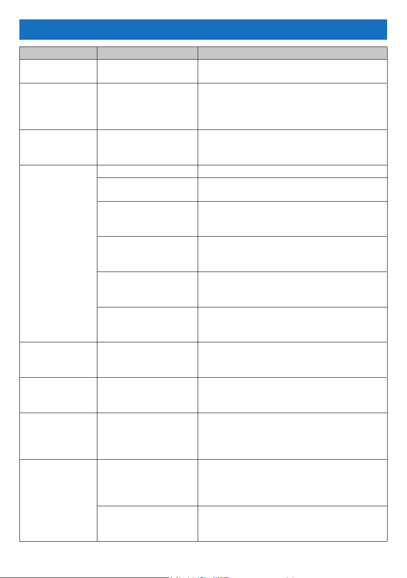
TROUBLESHOOTING
Fault Indication Potential Cause Remedy
Fault LED "ON". Numerous causes. See the LCD screen for the reason then go
to that section in this troubleshooting guide.
Internal
temperature
high.
High salt
warning.
Low salt or clean
cell or faulty cell.
Water
temperature low.
Water
temperature
high.
Water
temperature
sudden
increase.
Water ow fault. No water ow or low
No air ow around
the power pack or
excessively high salt.
Salt too high or short
on cell plates.
Low salt level. Check Water Balancing table (Page 6).
Build-up of calcium on
the cell plates.
Water temperature is
low.
Insufcient water ow
through the cell.
The cell could be
damaged or at the
end of its life.
Level low in one
direction but OK in the
other.
Water temperature is
below 10°C.
No water ow. Check for possible closed valve, pump
No water ow. Check for possible closed valve, pump
water ow.
Low speed pump not
supplying sufcient
water to cell housing.
Ensure power pack is mounted in a well
ventilated area away from chemicals and
fertilisers. Check Water Balancing table
(Page 6).
Check Water Balancing table (Page 6).
Check the cell is clear of debris (e.g. wire,
metal, touching plates, etc).
Calcium build-up needs to be removed.
See Cell Maintenance (Page 15).
Winter water temperature can be very low.
For every 1°C below 28°C the output can
drop 2-3% .
Ensure a full chamber of water is passing
over the cell. You may need to backwash
your lter. See Backwash (Page 9-10).
Damaged coating will reduce cell life and
reduce output. If all conditions are correct
then the cell could be at the end of its life.
Cell may need cleaning. See Cell
Maintenance (Page 15) or the cell may
have run its life in one direction.
The power pack will lower output when
water temperature goes below 10°C to
protect the cell plates.
fault, burst pipe.
fault, burst pipe.
Air in the cell housing, check for closed
valve, pump fault, burst pipe, etc. If none
detected contact your local Pool Pro
Professional for diagnosis.
Increase the speed of the pump until
housing is lled.
Page 16 www.poolpro.com.au
Page 17
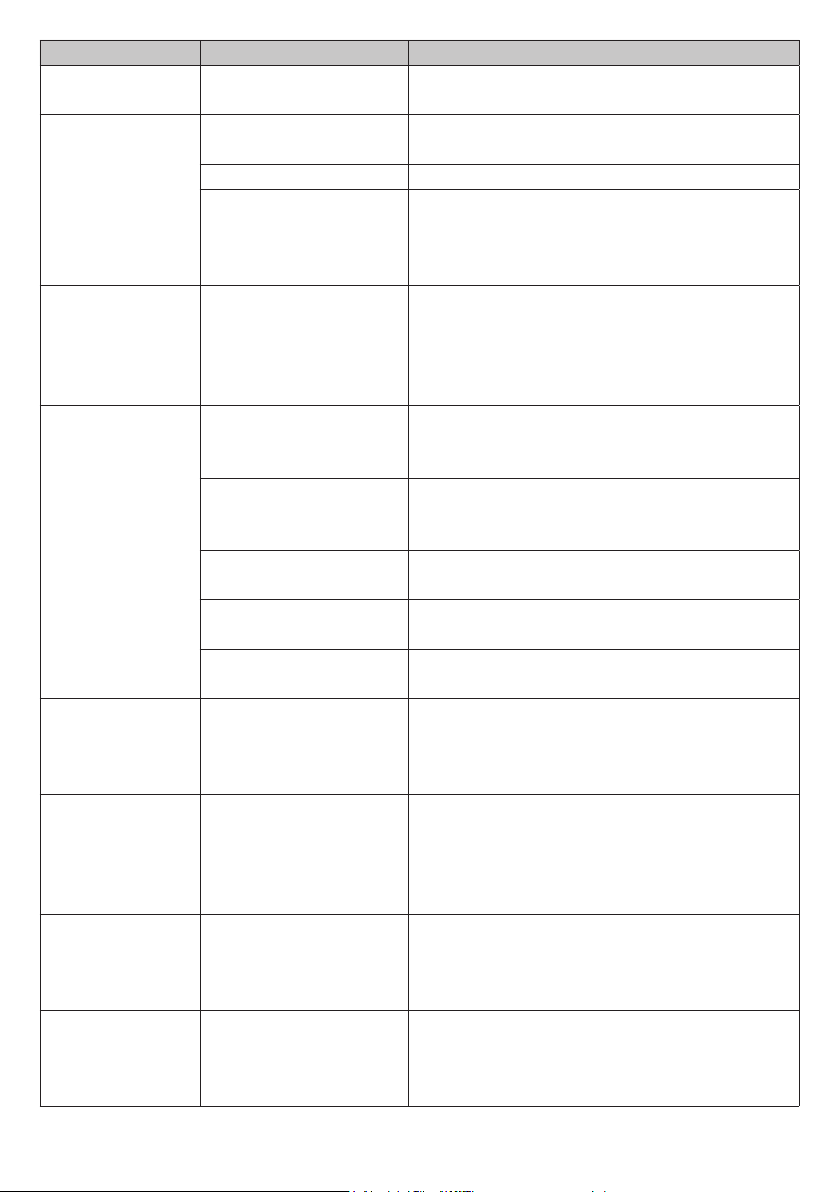
Fault Indication Potential Cause Remedy
No current ow
– no output.
Everything
displays OK but
not turning on.
Faulty Control or Main
PCB.
Incorrect timer
settings.
Check circuit breaker, possible faulty PCB call for service.
Press Power/Mode button until in ON
mode. Does it work now?
Yes, it works now. Check Timer Settings (Page 11-12).
No, it does not work. If the Fault LED is on, see LCD screen for
the reason then go to that section in this
troubleshooting guide. If only LCD screen
is on but nothing works - call for service.
Not operating at
all - comes on
but turns off.
Circuit breaker resets
but trips again.
1. Excessively high salt - check salt and
lower if needed. 2. Short across cell
plates - check cell plates for any metal
lying across plates. 3. Faulty rectiers,
transformer or cell cable - call for service.
Not operating at
all - no lights.
Not plugged into a
power point or power
Check the power pack’s power cord goes
into wall outlet and outlet is turned on.
point is off.
Plugged into power
Test wall outlet with a working appliance.
point and turned on
but still no power.
Wall outlet working
but still no power.
Pressed and reset but
still no power.
Circuit breaker stays
Check circuit breaker at bottom of power
pack. Press white button to reset if tripped.
If you have checked all of the above then
there is an internal fault - call for service.
Faulty circuit breaker - call for service.
out in a tripped state.
Sign of melting
or burning of the
cell connector
Possible moisture
entry to the plug.
If melted then it will need replacing
otherwise clean with WD40 or similar.
Return for service if melted.
plug.
Power pack only
works in one
Faulty rectiers,
transformer or PCB.
Return unit for service.
direction. No
output in one
direction.
Timer
functioning
Incorrect settings. Make sure Power/Mode is set to Auto.
Refer to Timer Settings (Page 11-12).
incorrectly in
Auto mode.
Pool pump outlet
not functioning
properly or
pump always on.
Pump not plugged into
chlorinator.
Check pump is plugged into the bottom of
the power pack. Check chlorinator is set
in Auto mode and not Manual for normal
running.
Page 17www.poolpro.com.au
Page 18
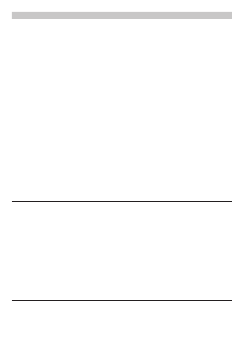
Fault Indication Potential Cause Remedy
Cell not
cleaning,
excessive
calcium build
up on cell or
power pack
not changing
direction.
Excessively high
calcium, change of
direction time set too
high or faulty PCB.
1. See Calcium Hardness levels in Water
Balancing table (Page 6) and adjust water
accordingly. 2. Change the Cell Cleaning
times (Page 10). 3. Manually try changing
direction by holding both [<] and [>] buttons
in for 3 seconds (you must be in the Main
Screen for this to work). Failure for this to
work could indicate a faulty PCB - return for
service.
Output reading
is less than
100%.
Low salt level. Check salt level. See Salt Test (Page 13).
Build up of calcium on
the cell plates.
Water temperature is
low.
Calcium build-up needs to be removed.
See Cell Maintenance (Page 15).
Winter water temperature can be very low.
For every 1°C below 28°C the output can
drop 2-3%.
Insufcient water
ow through the cell
housing.
The cell could be
damaged or at the
end of its life.
Level low in one
direction but OK in the
other.
Continuous build up of
Ensure a full chamber of water is passing
over the cell. You may need to backwash
your lter. See Backwash (Page 9-10).
Damaged coating will reduce cell life and
output. If all conditions are correct then cell
could be at the end of its life.
Cell may need cleaning. See Cell
Maintenance (Page 15) or the cell may
have run its life in one direction.
See Cell Maintenance (Page 15).
calcium.
Low or no
chlorine output.
Unit not working
correctly.
Go through Troubleshooting from the
beginning.
Unit not set correctly. Check basic settings such as output control
and timer running hours. Go through all
settings on pages 9-14 and balance water
accordingly.
Salt level is too low. Check Salt in the Water Balancing table
(Page 6).
pH is too high. Check pH in the Water Balancing table
(Page 6).
Stabiliser is too low. Check Stabiliser in the Water Balancing
table (Page 6).
Timer loses time
Cell at the end of its
life.
Battery life expired. Replace battery - return for service.
If full output is not reached then it could be
a failing cell.
when mains
power removed.
Page 18 www.poolpro.com.au
Page 19
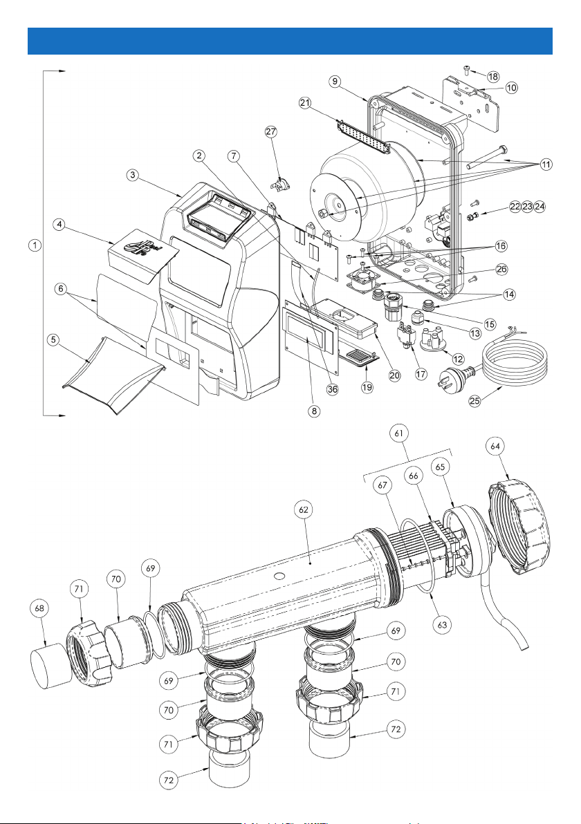
SCHEMATICS
Page 19www.poolpro.com.au
Page 20

# CODE DESCRIPTION
1 PPNDC15PP 15 Power Pack
PPNDC25_35_45PP
1
25/35 Power Pack
1 PPNDC55PP 45/55 Power Pack
2 PPN00895
Neptune Wire Loom-Multi PCD TB-GND Pin 1 to LCD PCB
RB-GND Pin 1 Black
3 PPN00364 Front Case
4 PPN00365 Top Vent Cover
5 PPN00367 Front Flap
6 PPN00437 Decal Sticker (Set Of 2)
7 PPN00693 Multi Triac Main PCB
8 PPN00496 LCD Display PCB
9 PPN00356 Aluminium Base
10 PPN00453-2 Mounting Bracket
11 PPN00024-1 Transformer 440VA (45/55g)
11 PPN00023-1 Transformer 300VA (25/35g)
11 PPN00022 Transformer 220VA (15g)
12 PPN00498
AC Socket Round - Pump Outlet Flush Mount White (Side
Wire Entry)
13 PPN00034 Cable Grommet 6N-4
14 PPN00501 Grommet Rubber Aux Hole Up To 19mm
15 PPN00488
Cell Plug SL-10 Male End Complete With Power Supply
Looms - Grease Filled
16 - Neptune Screw Stainless M3 x 12 S/S (Fan)
17 PPN00018L Circuit Breaker 91L-Series 3A (15/25/35/45g)
17 PPN00019L Circuit Breaker 91L-Series 5A (55g)
18 PPN00637 Mounting Bracket Screw 4mm x 16 S/S
19 PPN00368 Bottom Vent Cover
20 PPN00369 Fan Support Plate
21 PPN00370 Snap Fit Gauze
22 PPN00050 Earth Screw M5 S/S
23 PPN00051 Earth Nut M5 S/S
24 PPN00049 Internal Tooth Washer For Earth M5 S/S
25 PPN00011 Power Cord-AU
26 PPN00323 Fan 40x40x10mm (55G)
27 PPN00027 Thermostat 100DegC
30 PPN00047 Neptune Washer - 37x37x2.5 Zinc Plated
31 PPN00207
Neptune Wire Loom - Circuit Breaker Load to Thermostat
Brown
32 PPN00223 Neptune Wire Loom - AC Socket N to PCB N Blue
33 PPN00224 Neptune Wire Loom - AC Socket L to PCB PUMP-L Brown
34 PPN00348 Neptune Wire Loom - Circuit Breaker LINE to PCB A Brown
Page 20 www.poolpro.com.au
Page 21
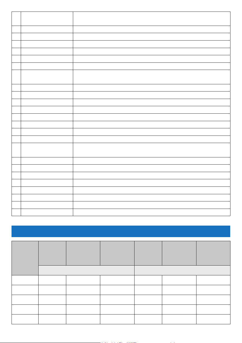
35 -
36 PPN00485 Neptune Ribbon Cable with Red line and Header Sockets
37 PPN00008 Wire Loom CC-05 - Earth Wire CPP/CPPS/Neptune Models
38 PPN00036 CPP/CPPS/Neptune Cable Tie 3mm
39 PPN00560 CPP/CPPS/Neptune Green Wall Plugs
40 PPN00217 CPP/CPPS/Neptune Screws Wall SS 5x25
41 PPN00053 Neptune Screw Stainless M4 x 8 S/S (Front Cover)
42 PPN00052
61 PPSL-CELL15RP 15g/hr Cell Only
61 PPSL-CELL25RP 25/hr Cell Only
61 PPSL-CELL35RPB 35g/hr Cell Only
61 PPSL-CELL45RPB 45g/hr Cell Only
PPSL-CELL55RPB-C
61
62 PPN00379 3-Way Cell Housing - Smokey
63 OR925 Cell Housing NDC O-Ring EPDM Rubber
64 PPN00380 Cell Cap Locking Ring NDC
65 PPSCCAP
66 PPN00530 Cell Clip 11 Plate Blue (15/25g)
66 PPN00666-2 Cell Clip 15 Plate Blue (35/45/55g)
67 PPN00322 Cell Spacer Rod Blue
68 PPN00691-1 Cell Blanking Bush
69 PPN00461-1 Cell Adapter Tail O-Ring
70 PPN00382 Cell Adapter Tail
71 PPN00381 Cell Nut Small
72 PPN00670-1 PVC Reducing Bush 50x40mm
Neptune Wire Loom - Terminal Block 1 Pin 2 to Terminal Block
2 Pin 2 Red
CPP/CPPS/Neptune Screw Stainless M3x6 S/S (SCR/Triac
Connection & PCB)
55g/hr Cell Only
Cell Cap (Includes Cable, Cover, Cap, Brassware, Washers,
Resin Filled)
CHLORINE PRODUCTION SPECIFICATIONS
Chlorine
Model
NDC15 15g 23g 120ml 120g 184g 0.96L
NDC25 25g 38g 200ml 200g 304g 1.60L
NDC35 35g 54g 280ml 280g 432g 2.24L
NDC45 45g 69g 360ml 360g 552g 2.88L
NDC55 55g 85g 440ml 440g 680g 3.52L
Output
Cal. Hypo.
Equivalent
(65%)
PER HOUR OVER 8 HOURS
Sod. Hypo.
Equivalent
(12.5%)
Chlorine
Output
Cal. Hypo.
Equivalent
(65%)
Sod. Hypo.
Equivalent
(12.5%)
Page 21www.poolpro.com.au
Page 22

TECHNICAL SUPPORT
For product support contact your local distributor or Pool Pro direct on Ph 1800 143 788
Fax 1800 778 820 Email [email protected] Web www.poolpro.com.au.
Information in this guide is intended to provide general information on a particular
subject(s) in good faith and is not an exhaustive treatment of such subject(s). Its use is
beyond the control of the author, contributor, publishers and distributors and should not
be relied upon without consulting your local Pool Pro Professional for comprehensive
advice. This guide includes subject(s) that should only be performed by or under the
direction and advice of your local Pool Pro Professional and under no circumstances
should the guide be used as a substitute for such professionals.
No representations or warranties are made that the content, advice and
recommendations in this guide are current, free from errors or omissions, or appropriate
for the user’s circumstances or abilities. No liability or responsibility is accepted for any
loss suffered as a result of any user’s reliance on such content.
Installations and repairs should only be carried out by qualied persons or Pool Pro
appointed agents. Pool Pro reserves the right to refuse warranty if any damage caused
to the chlorinator or auxiliary pool equipment that is not a result of a manufacturer’s
defect.
WARRANTY
Pool Pro warrants the Neptune Digital Chlorinator range (domestic) only for the original
purchaser and is non-transferable. Pool Pro warrants the power pack and cell to be
free of manufacturer’s defects in materials and workmanship for a total period of
three (3) years or up to 10,000 hours (whichever comes rst) from the date of original
purchase for domestic applications only (non-commercial applications on a singledwelling residential site). Domestic models are warranted for a period of one (1) year
from the date of original purchase on a commercial installation. Commercial models are
warranted for a period of two (2) years or up to 10,000 hours (whichever comes rst)
from the date of original purchase.
Warranty excludes damage caused by negligence, improper use, failure to undertake
regular maintenance, lack of care when using the product, foreign matter entering the
cell, water or foreign matter entering the power pack or junction box, incorrect water
balancing, incorrect installation, incorrect ow rates, inadequate ventilation, nor does
it cover normal wear and tear of the cell and power pack components, incorrect power
supply, corrosive and aggressive climate or location, insect or vermin infestation,
lightning strikes, ooding or any other event beyond the control of the manufacturer.
This product is only warranted for its intended use, in swimming pool and spa
installations. Water quality must be maintained in accordance with AS 3633-1989
Australian Standard Private Swimming Pools Water Quality and the product must be
installed in accordance with AS3000 Wiring Standards. Failure to comply with these
standards will void warranty.
The removal and return of the chlorinator to Pool Pro or a Pool Pro authorised
Page 22 www.poolpro.com.au
Page 23
nominated repair agent is the responsibility of the purchaser/warranty claimant. Repairs
under warranty can only be performed by an authorised nominated Pool Pro repair
agent. Proof of purchase must be shown to validate warranty.
Any liability of the manufacturer pursuant to the Trade Practices Act 1974, as amended
for a breach of a condition or warranty shall be limited to replacing or acquiring the
equipment (or part thereof) where the same has been supplied.
The maximum liability incurred by the manufacturer shall not in any case exceed the
contract price for the equipment or the product parts or components thereof claimed
to be defective. Further, the manufacturer shall not be liable for any loss, damage or
delay directly or indirectly caused by any malfunction of or defect of or failure of the
equipment other than as expressly provided in this warranty.
In the unlikely event that you have a problem with any Pool Pro product, simply contact
the original place of purchase.
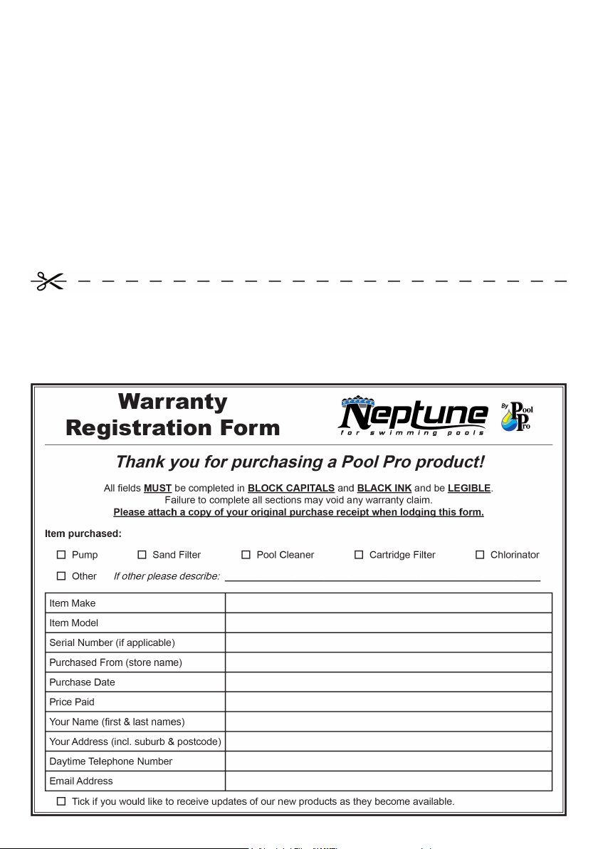
This warranty form and a copy of your original purchase receipt must be lodged within
30 days from date of purchase or any warranty claim may be voided. Post the Warranty
Registration Form and a copy of the purchase receipt to:
The POPS Group Pty Ltd (Pool Pro Products)
PO Box 4183, Loganholme QLD 4129, Australia
Page 23www.poolpro.com.au
Page 24
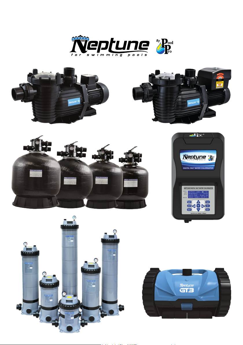
More products in the Neptune range...
PUMPS | SAND & CARTRIDGE FILTERS | CHLORINATORS | CLEANERS
 Loading...