

Pool Pro Neptune Series, Neptune NDC25, Neptune NDC35, Neptune NDC45, Neptune NDC55 Installation & Operating Manual
...

Congratulations on your recent purchase of your new Neptune Digital Salt Water
Chlorinator. Thank you for supporting Pool Pro Products. Please read this manual
carefully before installing, maintaining or troubleshooting your Neptune Digital Salt
Water Chlorinator.
While every effort has been made to ensure that the information contained in this guide
is accurate and complete, no liability can be accepted for any errors or omissions. Pool
Pro reserves the right to change the specications described herein at any time without
prior notice.
CONTENTS
Warnings & Safety Instructions ............................................................ Page 3
Packaging Contents ............................................................................. Page 4
Tools Needed ........................................................................................ Page 4
Installation Diagram .............................................................................. Page 4
Preparing the Pool ................................................................................ Page 5
Installing the Cell .................................................................................. Page 5
Installing the Chlorinator Power Pack ................................................... Page 5
Water Balancing ................................................................................... Page 6
Control Panel Operation ....................................................................... Page 7
Initial Start-up ....................................................................................... Page 8
The Main Screen .................................................................................. Page 9
Main Menu ............................................................................................ Page 9
Backwash ............................................................................................. Page 9-10
Brightness ............................................................................................. Page 10
Cell Cleaning ........................................................................................ Page 10
Chlor Boost ........................................................................................... Page 11
Chlor Setting ......................................................................................... Page 11
Clock/Timer .......................................................................................... Page 11-12
Contrast ................................................................................................ Page 13
Power/Mode ......................................................................................... Page 13
Pump Setting ........................................................................................ Page 13
Salt Test ................................................................................................ Page 13-14
Service Menu ........................................................................................ Page 14
Spa Mode ............................................................................................. Page 14
Winter Mode ......................................................................................... Page 14
Maintenance ......................................................................................... Page 15
Troubleshooting .................................................................................... Page 16-18
Schematics ........................................................................................... Page 19-21
Chlorine Production Specications ....................................................... Page 21
Technical Support ................................................................................. Page 22
Warranty ............................................................................................... Page 22-23
Page 2 www.poolpro.com.au

WARNINGS
This manual contains important information about the installation,
operation and safe use of this product, and should be given to the
owner and/or operator of this equipment. When installing and using
this electrical equipment, basic safety precautions should always
be followed. Failure to follow safety warnings and instructions in
this manual can result in serious injury and/or damage to your
equipment. Read and follow all warnings and instructions.
● The power supply internally contains live electrical components. There is a danger
of electric shock if opened.
● If the carton or product has been damaged or is wet: do not install the product,
contact your Pool Pro stockist.
● The product must be installed in accordance with AS/NZS 3000 Wiring Standards
and must be installed at least 3.5m away from the pool.
● CHLORINE GAS BUILDUP CAN OCCUR WITH IMPROPER WIRING: To reduce
the risk of personal injury, the power pack is designed so that the electrolytic cell
will only receive power when the pool pump is on. Otherwise, dangerous chlorine
gas build-up can occur. If the pump is not installed to the AC Socket (pump outlet)
on the power pack then the installer must ensure that the electrolytic cell is never
energised when the pool pump is OFF or water is not owing through the unit. A
venturi pipe is installed within the cell housing to eliminate any possible gas build
up, however it is RECOMMENDED that the cell housing be installed horizontally to
create a natural gas trap that acts as a safety device. Installation in any other way
may cause explosion, injury or death if the installer does not allow for gas removal.
● If you perform a backwash manually (without using the Backwash function on the
chlorinator) you must turn the chlorinator’s output down to the lowest percentage
setting via the “Chlor Setting” function.
● The pump rating must not exceed 8amps.
● Salt water may damage electrical components in the power pack.
● We DO NOT recommend the use of valves on the inlet or outlet of the cell housing.
If you do use a valve it is important that the valve cannot deadhead (lock closed)
while the pump is running. It is the installer’s responsibility to ensure some form of
ow control is installed in this instance and it disables the pump.
● Ideal salt levels range between 3000-3500ppm (parts per million). Salt levels
below 3000ppm and above 4000ppm may damage equipment and void any
warranty.
● Do not permit children, or persons with reduced physical, sensory or mental
capabilities to use or perform maintenance on this product. To reduce the risk of
accidents or incidents, service on the unit should only be performed by your local
Pool Pro Professional.
Page 3www.poolpro.com.au

PACKAGING CONTENTS
Wall
mounting
bracket
Drill with
6mm drill bit
Power
pack
Cell housing with
unions
TOOLS NEEDED
Basic PVC
ttings
Hacksaw PVC primer
INSTALLATION DIAGRAM
2 x 50/40
reducing
bushes
2 x green
wall plugs
with screws
& glue
User
manual
No.2
Phillips head
screwdriver
Page 4 www.poolpro.com.au

PREPARING THE POOL
Have your pool water tested by your local Pool Pro Professional. Ideal salt levels
range between 3000-3500ppm (parts per million). Salt levels below 3000ppm and
above 4000ppm may damage equipment and void any warranty.
For new pool installations, consult your pool builder or your local Pool Pro Professional
before adding salt. Some pool builders do not recommend the addition of salt for a
period of time following completion of the swimming pool.
Use Pool Pro Ultrane Pool Salt or Pool Pro Premium Pool Salt at the rate of 3.5kg
per 1000L of pool water. Mineral/magnesium chloride salts can also be used, including
Neptune Mineral Salt. Add 20%-30% extra product for mineral/magnesium salts.
Add salt to the shallow end of the pool. Use a pool brush to completely dissolve the
salt. Run the pool pump in the rst 8-12 hours to also help dissolve the salt.
NOTE: Never add salt/minerals directly to the skimmer box. High concentrations
of salt/minerals passing through pool equipment may cause damage. Remove
automatic pool cleaner from the pool before adding salt or other chemicals.
INSTALLING THE CELL
Check the O-Ring is installed in the cell housing and use a silicone based lubricant
(do not use petroleum based lubricants). It is recommended that the cell is installed
horizontally and the direction of water ow through the cell housing is entering from the
closed end of the cell housing and exiting from the end closest to the cell locking ring
(to reduce water hammer). Use pressure PVC solvent cement to glue cell unions to the
pipework. The cell must be installed so it is the last piece of equipment in the return line
to the pool.
A shut-off valve on the inlet or outlet of the cell housing is NOT recommended. If a
valve is required, it is recommended to install a non-return valve.
INSTALLING THE CHLORINATOR POWER PACK
The power pack must be installed outside of the pool zone, no more than 1.5m from
the cell, at least 1m above ground, away from chemicals and fertilisers (fumes may
damage the power pack) and in accordance with AS/NZS 3000 Wiring Standards.
Mount the power pack with the mounting bracket, green plugs and screws provided,
in a well ventilated position away from direct sunlight and rain (not in a closed
unventilated shed). If mounting on a post, install a waterproof non-metal at panel as a
backing plate.
Connect the lead from the cell electrode to the cell plug under the power pack, ensuring
a rm snap lock connection.
Plug the power pack into a 3 pin 10Amp weatherproof, RCD (Residual Current Device)
protected socket as per the AS/NZS 3000 Wiring Standards. Plug pump into the AC
socket at the bottom of the power pack.
Page 5www.poolpro.com.au
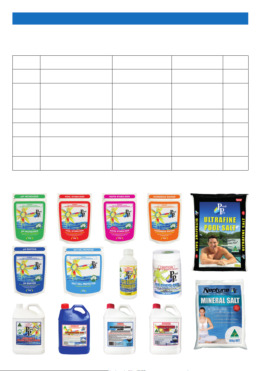
RECOMMENDED WATER BALANCING
Consult your local Pool Pro Professional to correctly balance your pool water. Follow
instructions on the packaging of each chemical. Always add chemicals to water, never
add water to chemicals.
Recommended Values To Increase Value To Decrease Value
pH
Free
Chlorine
T.A. (Total
Alkalinity)
Calcium
Hardness
Stabiliser 30 – 60ppm
Salt 3000 – 3500ppm
This is a guide only, does not constitute and should not be used as an alternative to specic professional
advice. Pool Pro and The POPS Group Pty Ltd accept no liability for any damage, loss or harm associated
with the use of this guide.
Concrete: 7.2 – 7.6 Fibreglass/
Vinyl: 7.0 – 7.2
1 – 3ppm
Concrete: 80 – 150ppm
Fibreglass/Vinyl: 80 – 120ppm
Concrete: 250 – 300ppm
Fibreglass/Vinyl: 150 – 200ppm
Add Pool Pro pH
Increaser (Soda Ash)
Increase the chlorine
output on the chlorinator
unit
Add Pool Pro pH Buffer
Add Pool Pro Hardness
Raiser
Add Pool Pro Stabiliser or
Pool Pro Rapid Stabiliser
Add Pool Pro Ultrane or
Premium Pool Salt
Add Pool Pro
Hydrochloric Acid
Add Pool Pro Chlorine
Out and decrease the
chlorine output on the
chlorinator unit
Add Pool Pro
Hydrochloric Acid
Add Pool Pro Calcium
Remover
Contact your Pool
Pro Professional for
advice
Partially empty the
pool and rell it
Test
Frequency
Weekly
Weekly
Fortnightly
Fortnightly
Fortnightly
Fortnightly
Page 6 www.poolpro.com.au

CONTROL PANEL OPERATION
BUTTON FUNCTION
Sets the chlorinator’s operating mode between AUTO, ON and OFF.
This is displayed on the LCD screen next to “Mode”.
Sets the chlorinator and pump to operate for 8 hours at 100% output.
Defaults to 8 hours but can be modied.
Reduces the chlorine output to 50%. Defaults to 50% but can be modied.
Sets the clock (time of day) and the timer (chlorinator operating times).
Measures the salt level of the pool water. Also shows the salt value.
Runs a backwash process to clean the media inside the pool lter system.
- Enters the Main Menu if pressed when the LCD screen is displaying the
Main Screen (see section “Main Screen” on page 9).
- Saves any changes made to the settings.
- Scrolls up any menus.
- Adjusts values of any options selected.
- Scrolls down any menus.
- Adjusts values of any options selected.
- Exits menus.
- Returns to the previous screen.
Used during service by qualied Pool Pro Professionals.
Page 7www.poolpro.com.au
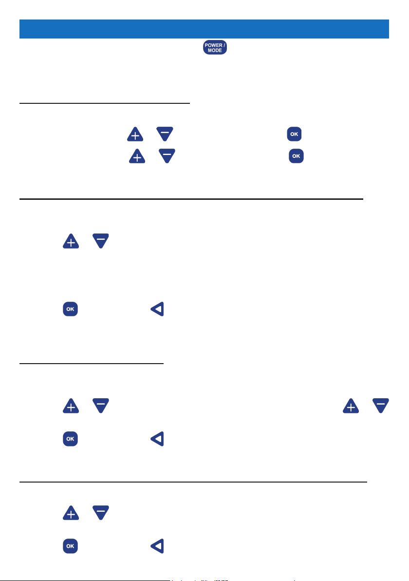
INITIAL START-UP
Turn on the chlorinator unit by pressing the button. Wait for the chlorinator unit to
run through a start-up sequence.
SETTING THE CLOCK (time of day)
1. “START UP CLOCK SET” will display on the LCD screen.
2. “HH” will ash. Press or to change the hour. Press to save.
3. “MM” will ash. Press or to change the hour. Press to save.
SETTING THE TIMER / RUN PERIOD (daily run times of the chlorinator)
1. “START UP RUN PERIODS” will display on the LCD screen. “2 CYCLES/DAY” will
ash.
2. Press or to scroll through the cycles.
Select from the following cycles for your chlorinator to operate:
(a) “2 CYCLES/DAY” = 6am - 10am and 4pm - 8pm
(b) “1 CYCLE AM” = 8am - 4pm
(c) “1 CYCLE PM” = 8pm - 4am
3. Press to save or press to exit without saving. If these cycle times are not
suitable, you can change them in the Clock/Timer function – see page 11-12.
SETTING UP THE POOL SIZE
1. “START UP INFORMATION” will display on the LCD screen. The litre quantity for
“POOL SIZE” will ash.
2. Press or to change the litre quantity by 1,000L increments, hold or
to change the litre quantity by 5,000L increments.
3. Press to save or press to exit without saving.
SETTING UP THE MINERAL TYPE (if your pool uses salt or mineral mix)
1. “START UP INFORMATION” will display on the LCD screen. “SALT” will ash.
2. Press or to change the type of mineral used in the pool water. Select from
“SALT” or “MINERAL MIX”.
3. Press to save or press to exit without saving.
Page 8 www.poolpro.com.au
 Loading...