

Page 1

CommandPak™ Control System CPCS
BACnet /IP User’s Guide
DOCUMENT #: SVW07-MPKBACNIP-20171020
UPDATED: OCTOBER 2017
PoolPak MPK with
Page 2
MPK with CommandPak™ Control System BACnet /IP User’s Guide
INTRODUCTION
PoolPak® dehumidifiers equipped with an CommandPak™ Control
System (CPCS) can be directly connected to a BACnet/IP based
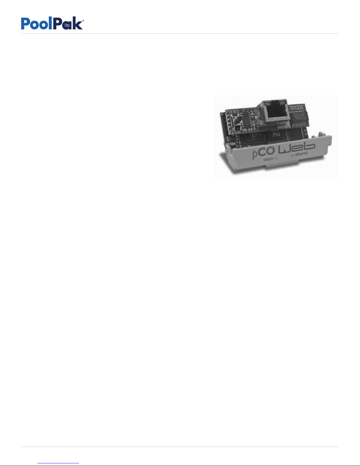
Building Automation System (BAS). Based on Carel’s pcoWeb serial
card, the interface allows connection to an Ethernet network. 80 control
points, including all basic information and set points for the PoolPak
dehumidification system, are available through the interface.
COMMANDPAK™ CONTROL SYSTEM CONFIGURATION FOR BACNET
PoolPak® dehumidifiers equipped with CPCS can be directly connected to a BACnet/IP based Building Automation System
(BAS). Based on Carel’s pcoWeb serial card, the interface allows connection to an Ethernet network. 80 control points,
including all basic information and set points for the PoolPak dehumidification system, are available through the interface.
The BACnet configuration parameters for the controller are accessed in the configuration menu. To access this menu:
1. Press the program key () on the RIU or CM1 module
2. Scroll down to “Service” then press Enter ().
3. Scroll up for the service password “0005”, then press Enter ().
4. Scroll down to “Unit Config” then press Enter ().
5. Scroll down for the advanced password of “9995”, then press Enter ().
6. Use the arrow keys to scroll down to “BAS Interface”, then press Enter ().
7. Press the Enter key to move the cursor to different fields. Use the arrow keys to change the following parameters
as needed:
• TYPE – BACne t – This is the type of BAS system connecting.
• BAUD R ATE – 1920 0 – Sets the baud rate for the onboard serial port. It must be set to 19200 for use with the
BACnet interface. 19200 is the factory default setting for this parameter. Note that this is the baud rate of the
internal serial interface between the BACnet board and the PoolComPak controller. The baud rate of the BACnet
MS/TP connection is set with a utility program from Carel. See the Interface Card Field Setup and Configuration
section of this document for more information.
• BAS Addr – 0 01 – Sets the address of the BACnet interface card in the serial slot of the controller. It must be
set to 1 for proper operation of the BACnet interface. The factory default setting is 1. Note that this is the internal
serial address of the BACnet board. The station address for the BACnet MS/TP network is set with a utility program
from Carel. See the Interface Card Field Setup and Configuration section of this document for more information.
8. After changing any of the above parameters, reboot the controller by cycling power with the unit control power
switch. This switch is located within or adjacent to the main control panel of the dehumidifier.
© 2017 PoolPak LLC. All rights reserved. Page 2
Page 3

MPK with CommandPak™ Control System BACnet /IP User’s Guide
INTERFACE CARD FIELD SETUP AND CONFIGURATION
The BACnet interface card is shipped from the factory with the following default settings:
• DHCP: ON
• IP Address:
• Netmask:
• Gateway:
• DNS1:
• DNS2:
• BACnet ID (Device Instance): 77000
• BACnet Type: IP
Change the above card settings on the controller or keypad as follows:
1. Press and hold the Alarm ( ) and Enter () keys.
2. Arrow down to “Other Information” then press Enter ()
3. Arrow down to “PCOWEB/NET CONFIG” then press Enter ()
4. Arrow down to “PCOWEB,” then press Enter (). (PCONET is for MS/TP)
5. Use the Enter () key to move the cursor to the value you need to change. Use the arrow keys to change the value.
6. The last screen will say “pCONET CONFIG ENABLE”, then “Update pCOnet?” Select “YES” then press Enter ().
7. After changing any of the above parameters, reboot the controller by cycling power with the unit control
power switch.
— . — . — . —
— . — . — . —
— . — . — . —
— . — . — . —
— . — . — . —
The above parameters along with UDP Port, Description, and Location can be changed through the web interface available
through the Ethernet connection on the BACnet card. To access this page, enter the following address in a web browser:
http://”IP Address”/config where IP Address is the address assigned to the card manually or through a DHCP server.
The computer used must be on the same subnet as the BACnet card. Contact PoolPak Service at 800-959-7725 for login
information.
For any difficulty changing these parameters, contact PoolPak Service at 800-959-7725 for assistance.
PHYSICAL NETWORK CONNECTION
The 8P8C (“RJ-45”) Ethernet socket is located on the pCOWeb interface card. The pCOWeb card occupies the serial card
slot directly below the keypad built into the CM1 control module. This control module is located in the main control panel
of the PoolPak dehumidifier.
The Ethernet connection to the interface card should comply with standard installation practices. Use care to route the cable
away from sources of interference and keep the maximum cable length less than 300 feet.
CONTROL POINTS MAPPING
80 objects are accessible through the BACnet interface. Set points, sensor values, and enumerated variables are shared
as analog-value objects. Status information points are shared as binary-value objects. The interface card is pre-configured
at the factory with a device instance number of 77000. To change this value, follow the instructions shown in the Interface
Card Field Setup and Configuration section of this document.
© 2017 PoolPak LLC. All rights reserved. Page 3
Page 4
MPK with CommandPak™ Control System BACnet /IP User’s Guide
The following table lists the available points along with their object types and instance numbers.
OBJECT
TYPE
READ/
WRITE
OBJECT
INSTANCE
OBJECT NAME DESCRIPTION UNITS
AV R 1 CPR1_xwfCprCur System 1 Cmpr Current Amps
AV R 2 CPR2_xwfCprCur System 2 Cmpr Current Amps
AV R 3 CPR3_xwfCprCur System 3 Cmpr Current Amps
AV R 4 xwfAirOffEvpRelHum Air Leaving Evap Rel Humidity (RH) %
AV R 5 xwfAirOffEvpTmp Air Leaving Evap Temperature °C
AV R 6 xwfAuxAirCoolPercent Aux Air Cooling Percent Output %
AV R 7 xwfAuxAirHeatPercent Actual Aux Air Heating % Output %
AV R 8 xwfAuxAirHeatPercent_1 Calc Aux Air Heating % Output %
AV R 9 xwfExhAirVol Exhaust Air Volume CFM
AV R 10 xwfExhFanCur Exhaust Fan Current Amps
AV R 11 xwfMixBoxPctOpen Mixing Box Position %
AV R 12 xwfOutAirDewpoint Outside Air Dewpoint °C
AV R 13 xwfOutAirRelHum Outside Air RH %
AV R 14 xwfOutAirTmp Outside Air Temperature °C
AV R 15 xwfOutAirVol Outside Air Volume CFM
AV R 16 xwfOutDprFbk Outside Air Damper Position %
AV R 17 xwfPool1WtrTmp Pool1 Water Temperature °C
AV R 18 xwfPool2WtrTmp Pool2 Water Temperature °C
AV R 19 xwfPurAirVol Purge Air Volume CFM
AV R 20 xwfPurFanCur Purge Fan Current Amps
AV R 21 xwfRtnAirDewpoint Return Air Dewpoint °C
AV R 22 xwfRtnAirRelHum Return Air RH %
AV R 23 xwfRtnAirTmp Return Air Temperature °C
AV R 24 xwfSetEvtMinMixBoxPos Event Min Mix Box Position %
AV R 25 xwfSetMaxMixBoxPos Max Mix Box Position %
AV R 26 xwfSetMinMixBoxPos Min Mix Box Position %
AV R 27 xwfSetPool1WtrTmp Pool1 Water Temp Setpoint °F
AV R 28 xwfSetPool2WtrTmp Pool2 Water Temp Setpoint °F
AV R 29 xwfSetRtnAirRelHum Return Air RH Setpoint %
AV R 30 xwfSetRtnAirTmp Return Air Temp Setpoint °F
AV R 31 xwfSupAirTmp Supply Air Temperature °C
AV R 32 xwfSupAirVol Supply Air Volume CFM
AV R 33 xwfSupFanCur Supply Fan Current Amps
AV R 34 xwfSurTmp Surface Temperature °C
AV R 1001 CPR1_xwiActiveFaultCode Cmpr1 Fault Code See below
AV R 1002 CPR1_xwiMode Cmpr1 Actual Mode See below
© 2017 PoolPak LLC. All rights reserved. Page 4
Page 5
— BACnet Points List continued
MPK with CommandPak™ Control System BACnet /IP User’s Guide
OBJECT
TYPE
READ/
WRITE
OBJECT
INSTANCE
OBJECT NAME DESCRIPTION UNITS
AV R 1003 CPR2_xwiActiveFaultCode Cmpr2 Fault Code See below
AV R 1004 CPR2_xwiMode Cmpr2 Actual Mode See below
AV R 1005 CPR3_xwiActiveFaultCode Cmpr3 Fault Code See below
AV R 1006 CPR3_xwiMode Cmpr3 Actual Mode See below
AV W 1007 twiSetInpEvtMinMixBoxPos Event Min Mix Box Pos Setpoint %
AV W 1008 twiSetInpMaxMixBoxPos Max Mix Box Pos Setpoint %
AV W 1009 twiSetInpMinMixBoxPos Min Mix Box Pos Setpoint %
AV W 1010 twiSetInpPool1WtrTmp Pool1 Water Temp Setpoint °F
AV W 1011 twiSetInpPool2WtrTmp Pool2 Water Temp Setpoint °F
AV W 1012 twiSetInpPurMixBoxPos Purge Mode Mix Box Setpoint %
AV W 1013 twiSetInpRtnAirRelHum Return Air RH Setpoint %
AV W 1014 twiSetInpRtnAirTmp Return Air Temp Setpoint °F
AV R 1015 xwiAuxAirCoolStgRqd Aux Air Cool Requested (Rqd) Stages
AV R 1016 xwiAuxAirHeatStgRqd Aux Air Heat Stages Rqd Stages
AV R 1017 xwiCpr1ModeReq Cmpr1 Mode Requested Stages
AV R 1018 xwiCpr2ModeReq Cmpr2 Mode Requested Stages
AV R 1019 xwiCpr3ModeReq Cmpr3 Mode Requested Stages
AV R 1020 xwiDehStgRqd Dehumidification Stages Rqd Stages
AV R 1021 xwiHeatCoolStgRqd Heat/Cool Stages Rqd Stages
AV R 1022 xwiLastUnitGnlFltCode Last Unit Fault Code See below
AV R 1023 xwiSenGnlFltCode Sensor Fault Code See below
AV R 1024 xwiUnitGnlFltCode Unit Fault Code See below
BV R 1 xbAlarm_DO Alarm Output on/off
BV R 2 xbAuxAirCool1_DO Aux Cool 1 Output on/off
BV R 3 xbAuxAirCool2_DO Aux Cool 2 Output on/of f
BV R 4 xbAuxAirCool3_DO Aux Cool 3 Output on/of f
BV R 5 xbAuxAirHeat1_DO Aux Air Heat 1 Output on/off
BV R 6 xbAuxAirHeat2_DO Aux Air Heat 2 Output on/off
BV R 7 xbAuxAirHeat3_DO Aux Air Heat 3 Output on/off
BV W 8 xbBASForceNoPurMod Force NoPurge Mode on/off
BV W 9 xbBASForceOccupied Force Occupied on/off
BV W 10 xbBASForcePurMod Force Purge Mode on/off
BV W 11 xbBASForceUnoccupied Force Unoccupied on/off
BV R 12 xbExhFan_DO Exhaust Fan Output on/off
BV R 13 xbOccupied Occupied Mode on/off
BV R 14 xbPool1AuxWtrHeat_DO Pool1 Aux Heat Output on/of f
BV R 15 xbPool2AuxWtrHeat_DO Pool2 Aux Heat Output on/off
© 2017 PoolPak LLC. All rights reserved. Page 5
Page 6
MPK with CommandPak™ Control System BACnet /IP User’s Guide
OBJECT
TYPE
READ/
WRITE
OBJECT
INSTANCE
OBJECT NAME DESCRIPTION UNITS
BV R 16 xbPoolWtrCndFlowA Pool Water Flow Circuit A on/off
BV R 17 xbPoolWtrCndFlowB Pool Water Flow Circuit B on/off
BV R 18 xbPurFan_DO Purge Fan Output on/off
BV R 19 xbPurMod Purge Mode Active on/off
BV R 20 xbRemExhFan_DO Remote Exhaust Fan Output on/of f
BV R 21 xbSmartPump1_DO Pool Pump Output on/off
BV R 22 xbSupFan_DO Supply Fan Output on/off
COMPRESSOR ACTIVE FAULT CODE
AV1001, AV1003 and AV1005 are enumerated values indicating the most significant active fault in each compressor
system of the dehumidifier. The present value for these objects can be decoded as follows:
• 0 – Normal
• 1 – Run/Pumpdown switch in pumpdown position
• 2 – System warmup in progress. Normal for 5 minutes after power-on.
• 3 – Liquid temperature sensor failed
• 4 – Suction temperature sensor failed
• 5 – Compressor current sensor failed
• 6 – Suction pressure transducer failed
• 7 – Discharge pressure transducer failed
• 13 – Low refrigerant pressure detected
• 14 – High compressor motor temperature detected
• 15 – High refrigerant pressure detected
• 50 – Compressor locked out due to 10 faults since last power cycle
COMPRESSOR SYSTEM MODE AND MODE REQUESTED
AV1002, AV1004, AV1006 (Modes) and AV1017, AV1018, AV1019 (Modes Requested) are enumerated values indicating
the operation mode of the corresponding compressor system. The present value for these objects can be decoded
as follows:
• 0 – Compressor Off
• 1 – Air Heating Mode. Recovered heat is being used to heat the air.
• 3 – Pool Water Heating Mode. Recovered heat is being used to heat the water.
• 4 – Air Cooling Mode. Recovered heat is being rejected to an external air or water-cooled condenser.
SENSOR FAULT CODE (XWISENGNLFLTCODE)
AV1023 is an enumerated value indicating a failed sensor. The value for this object is decoded as follows:
• 0 – Normal. No sensors in failure.
• 1 – Return air temperature
• 2 – Return air humidity
• 3 – Supply air temperature
• 4 – Outside air temperature
© 2017 PoolPak LLC. All rights reserved. Page 6
Page 7

• 5 – Supply air CFM
• 6 – Exhaust air CFM
• 7 – Purge air CFM
• 8 – Outside air CFM
• 9 – Supply fan current signal
• 10 – Exhaust fan current signal
• 11 – Purge fan current signal
• 13 – Pool 1 temperature
• 14 – Pool water circuit A pressure drop
• 15 – Pool 2 temperature
• 16 – Pool water circuit B pressure drop
• 19 – Air off evaporator temperature
• 20 – Air off evaporator humidity
• 22 – Evaporator bypass damper position feedback
• 24 – Outside air damper position feedback
• 25 – Recirc air damper position feedback
• 26 – Space pressure
• 27 – Return air CO2 level
• 28 – Surface temperature
• 29 – Outside air filter pressure drop
• 30 – Return air filter pressure drop
MPK with CommandPak™ Control System BACnet /IP User’s Guide
UNIT FAULT CODE AND LAST UNIT FAULT CODE (XWIUNITGNLFLTCODE)
AV1022 and AV1024 are enumerated values indicating a general fault condition for the unit. The last fault (AV1022)
indicates the most recent previous fault condition for the unit. The value for these objects is decoded as follows:
• 0 – Normal
• 1 – Coil freeze warning active
• 2 – Fire trip mode active
• 3 – Smoke purge mode active
• 4 – Supply fan not running
• 5 – Exhaust fan not running
• 6 – Purge fan not running
• 7 – Exhaust fan VFD fault active
• 8 – Supply fan VFD fault active
• 9 – Purge fan VFD fault active
• 10 – System startup active Normal for 5 minutes after power on.
• 11 – Supply fan deadheaded. Supply fan requested on with both outside air and recirc air dampers less than
25% open.
• 12 – Aux heating system failure
• 13 – Aux cooling system failure
• 14 – Compressor Module 1 fault active
• 15 – Compressor Module 2 fault active
• 16 – Compressor Module 3 fault active
© 2017 PoolPak LLC. All rights reserved. Page 7
Page 8

MPK with CommandPak™ Control System BACnet /IP User’s Guide
CHANGING A SET POINT
Two analog value objects are allocated for each set point, a readable value and a writeable value. To change a set point,
set the present value of the writeable object to the new set point value. Verify that the controller accepted the change by
reading the value of the corresponding readable object. The controller applies limits to the set point values. If the BAS
tries to set an inappropriate value, the readable object will show the min or max allowed value instead of the requested
value. The BAS can detect this event by verifying the change in the readable object’s present value. The following limits are
applied by the controller:
• Return Air Temperature: 75°F – 95°F
• Return Air Humidity: 40% – 65%
• Pool Water Temperature: 75°F – 95°F
• Damper Position: 0% – 100%
• Mixing Box Position: 0% – 100%
Set points for temperature are represented by integer values in degrees Fahrenheit.
CONTROLLING OCCUPANCY MODE
The BAS can control the dehumidifier’s Purge mode directly. This control overrides all internal schedules and controls except
for the freeze protection algorithm. To force purge mode, set the xbBASForcePurMod object value to the ON state and the
xbBASForceNoPurMod object value to the OFF state. To force non-purge mode, set the value of the xbBASForcePurMod
object to OFF and the xbBASForceNoPurMod object to ON.
ACTIVE ALARM FLAG CONTROL
The xbAlarm_DO binary value object indicates the status of the system alarm flag. This status corresponds to the red light
inside the alarm button of the control module, CM1. When the present value of this object is ON, there is an uncleared
alarm present in the controller. If there are no active alarms present, the value of xbAlarm_DO will change to OFF.
If there are still active alarms present, the value of xbAlarm_DO will remain ON.
To determine the actual alarm condition, the BAS can examine the present value of the active fault objects. See the Fault
Code sections earlier in this document for a list of possible states.
© 2017 PoolPak LLC. All rights reserved. Page 8
Page 9
MPK with CommandPak™ Control System BACnet /IP User’s Guide
SYMPTOM POSSIBLE CAUSE SOLUTION
The interface card is not properly
connected to the network.
The dehumidifier cannot be seen
on the BACnet network.
Power to the controller is off.
The BAS is trying to access the interface
with the wrong device instance number.
The variable values sent by the
controller are different than
those shown on the RIU.
Set point changes are different
than requested by the BAS.
For questions about the interface that are not answered in this document,
please contact the PoolPak Service department at 800-959-7725.
Incorrect setting of the
BAS configuration parameters
in the service menu.
Requested set point change is
outside of the acceptable range.
Correct network wiring.
If safe to do so, turn on the main
disconnect and the control power
switch(CPS) in the control
compartment of the dehumidifier.
Follow the instructions in this
document to set the instance number
to a value appropriate for the BAS.
Correct the parameter values to match
the settings shown in this document.
Select set points based
on the acceptable range.
BACnet® is a registered trademark
of Amer ican Society of H eating,
Refrigerating and Air-Conditioning
Enginee rs (ASHRAE). T his
tradem ark is use d in the text , but
for the sa ke of readab ility, it is no t
individually marked.
With more than 45 years of experience in indoor pool dehumidification equipment manufacturing, PoolPak® LLC is the most well-known brand
in the industry. Our people and products work daily to improve the quality and comfort of indoor pool environments. PoolPak® dehumidification
solutions include a variety of heating, ventilation, and air conditioning systems, in addition to an industry-leading PoolPak® support network. For more
information, please visit www.PoolPak.com.
3491 Industrial Drive
York, Pennsylvania 17402 USA
800-959-7725 Fax 717-757-5085
© 2017 PoolPak LLC. All rights reserved. SVW07-MPKBACNIP-20171020
 Loading...