

Page 1
DOOR ALARM
Installation Instructions
IMPORTANT
READ THOROUGHLY BEFORE USING ALARM
DOOR ALARM
PASS THRU
SWITCH
SENSING
WIRES
SENSOR
MAGNET
The horn is 85dB at 10 feet
LED
HORN
SENSOR
SWITCH
The product has been designed to aid in the detection of unwanted
intrusio ns into unsuper vised a reas. P OOLGUARD DAPT-2 IS A
SAFETY ALARM SYSTEM AND NOT A LIFE SAVING DEVIC E. It
should be used in conjunction with the safety equipment currently in use
and should not affect existing safety procedures.
WARRANTY AND REPAIRS
POOLGUARD is sold with a limited warranty to cover defects in parts
and workmanship for one year from date of purchase. (Retain proof of
purchase). If Poolguard exhibits a defect, please call our Customer
Service department at 1-800-242-7163. Unauthorized returns will not be
accepted. Proper repair is only ensured when the unit is returned to the
manufacturer. Visit our website at www.poolguard.com to fill out your
warranty registration information.
SWIMMING POOL SAFETY TIPS
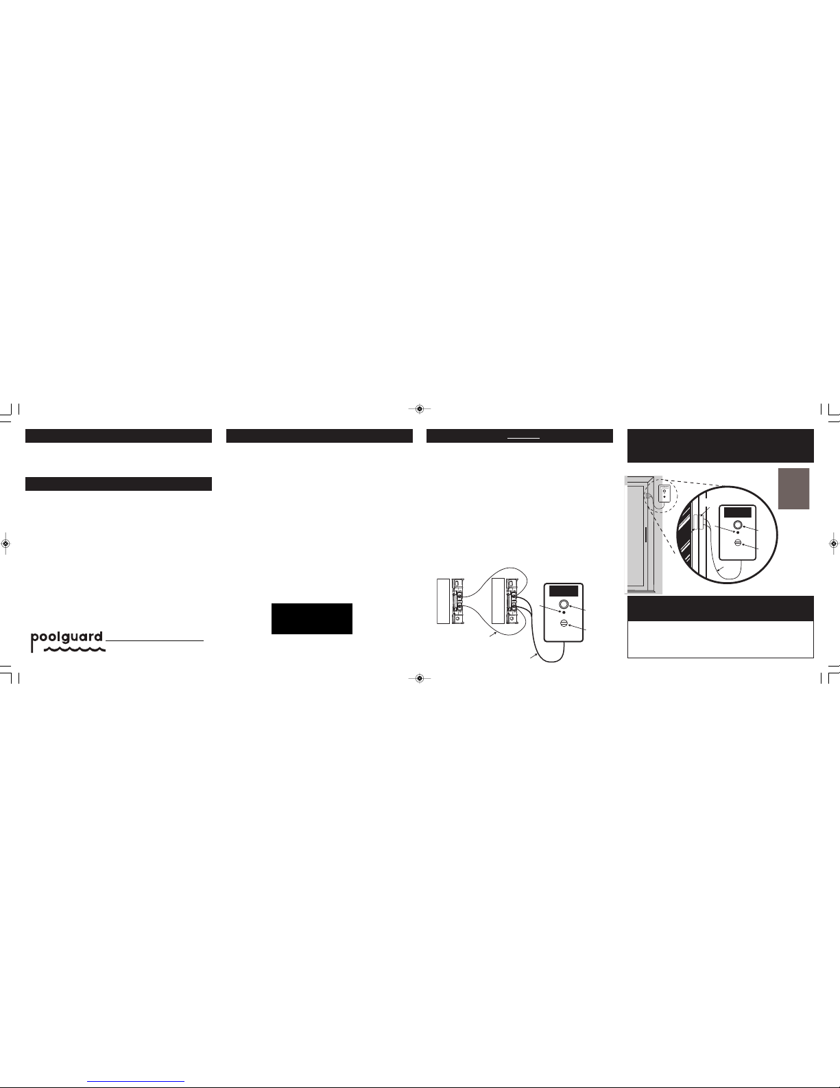
CONNECTING DOOR ALARM TO SENSOR SWITCHES
READ THE DOOR ALARM MANUAL FOR INSTALLATION ON ONE DOOR FIRST:
THE SENSOR WIRES ARE PERMANENTLY CONNECTED TO THE DOOR
ALARM. CONNECT BOTH SENSOR WIRES COMING FROM THE DOOR ALARM
TO THE SENSOR SWITCH ON THE DOOR FRAME. THEN USE THE SUPPLIED
JUMPER WIRES TO CONNECT TO THE SCREEN DOOR SENSOR SWITCH
(SEE DIAGRAM BELOW). THE TWO SENSORS SHOULD BE HOOKED UP IN
PARELLEL WITH EACH OTHER.
• THE PLASTIC COVERS ON THE SENSOR SWITCHES & SENSOR
MAGNET MUST BE REMOVED BEFORE INSTALLATION
• SWITCHES GO ON THE FRAME BY THE DOOR
• MAGNETS GO ON THE DOOR ITSELF – SEE PICTURE IN MANUAL
EQUIPMENT NEEDED
A. ONE DOOR ALARM AND 2 MOUNTING SCREWS
B. ONE SET OF SENSOR SWITCH AND SENSOR MAGNET AND 4 SCREWS
FOR DOOR FRAME & DOOR
C. ONE SET OF SENSOR SWITCH AND SENSOR MAGNET, JUMPER WIRES,
AND 4 SCREWS
– FOR SCREEN DOOR FRAME AND SCREEN DOOR
IF YOU HAVE ANY QUESTIONS CALL US AT 1-800-242-7163
LOW BATTERY FUNCTION
5.
MODEL DAPT-2
MEETS UL 2017
DOOR ALARM
MAIN DOOR
PASS TH RU
SWITCH
SENSING
WIRES
LED
HORN
SCREEN DOOR
SENSOR MAGNET
SENSOR
SWITCH
SENSOR MAGNET
JUMPER
WIRES
SENSOR
SWITCH
PBM
INDUSTRIES, INC.
P.O. Box 658
NORTH VERNON, IN 47265
812-346-2648
MAD E IN THE U SA
REV. 5-09
PBM
®
INDUSTRIES, INC.
• Supervise children at all times.
•Never permit swimming alone. Never leave a child alone, even
to answer the telephone.
•Always remove the entire solar cover from a pool before
swimming.
•Remember that alcohol and water safety do not mix.
•Have your pool area fenced and the gate locked to prevent
unauthorized entry to the pool,and install a gate alarm.
•Lock and secure all doors in the house which permit easy
access to the pool,and install a door alarm.
•Have a responsible adult teach swimming and water safety to
your children.
•Maintain clean, clear water in the pool.
•Do not swim during electrical storms.
•Do not permit bottles, glass, or sharp objects to be used
around the pool.
•Ask your pool dealer how you can improve your pool
safety––they will be glad to assist you.
•Above all: remember that common sense,awareness, and
caution will allow you to enjoy your pool.
Figure 1
When the 9-volt battery is low, the door alarm horn will chirp once every
10 seconds–this means it is time to install a new battery, Battery life is
approximately 1 year. Test your door alarm weekly by opening the door
and allowing the alarm to sound.
INSTALLATION OF OPTIONAL SCREEN DOOR KIT
6.
Figure 5
www.poolguard.com
PG DAPT-2 Manual 122208:Layout 1 5/14/09 12:42 PM Page 1
Page 2
INSTALLING THE 9V BATTERY
(FIG. 2)
DAPT-2 Maximum Current Input = 19mA
9V dc alkaline battery. Energizer No. 522 or Duracell No. MN1604
1.
SENSOR
SWITCH
SENSOR MAGNET
PLASTIC COVER
TERMINALS
KNOCKOUT
Figure 4
A. Remove the assembly screw from the back of the door alarm and
remove the top cover. (See Figure 2)
B. Pull down the battery spring and install the 9v battery (see figure 2).
NOTE: If the battery spring is not in the correct position under the
battery, the alarm will not go back together.
C. When the 9v battery is installed, the LED will flash once every 10
seconds. When the alarm sounds, the LED will flash once every
second.
D. Reassemble the door alarm with the assembly screw. NOTE: Once
the battery is installed the alarm may sound accidentally until the
sensors are connected properly.
A. Determine the best location. The door alarm must be installed at least
54” above the threshold of the door.
B. With a pencil, mark 2 spots 2 1/2” apart vertically (up & down) where
the alarm will be mounted. These 2 marks are where the 2 larger
supplied screws will be inserted into the wall to hang the door alarm.
C. Insert the 2 larger supplied screws into the wall on the 2 marks. Leave
about 5/32” (not including the head of the screw) of the screw from
the wall.
D. Hang the door alarm on the mounted screws and pull downward until
the screws are positioned in the small end of the hanger holes in the
back of the alarm.
E. If you purchased the OPTIONAL
Screen Door Kit see section 6.
(Figure 5)
INSTALLING DOOR SENSOR
(FIG. 4)
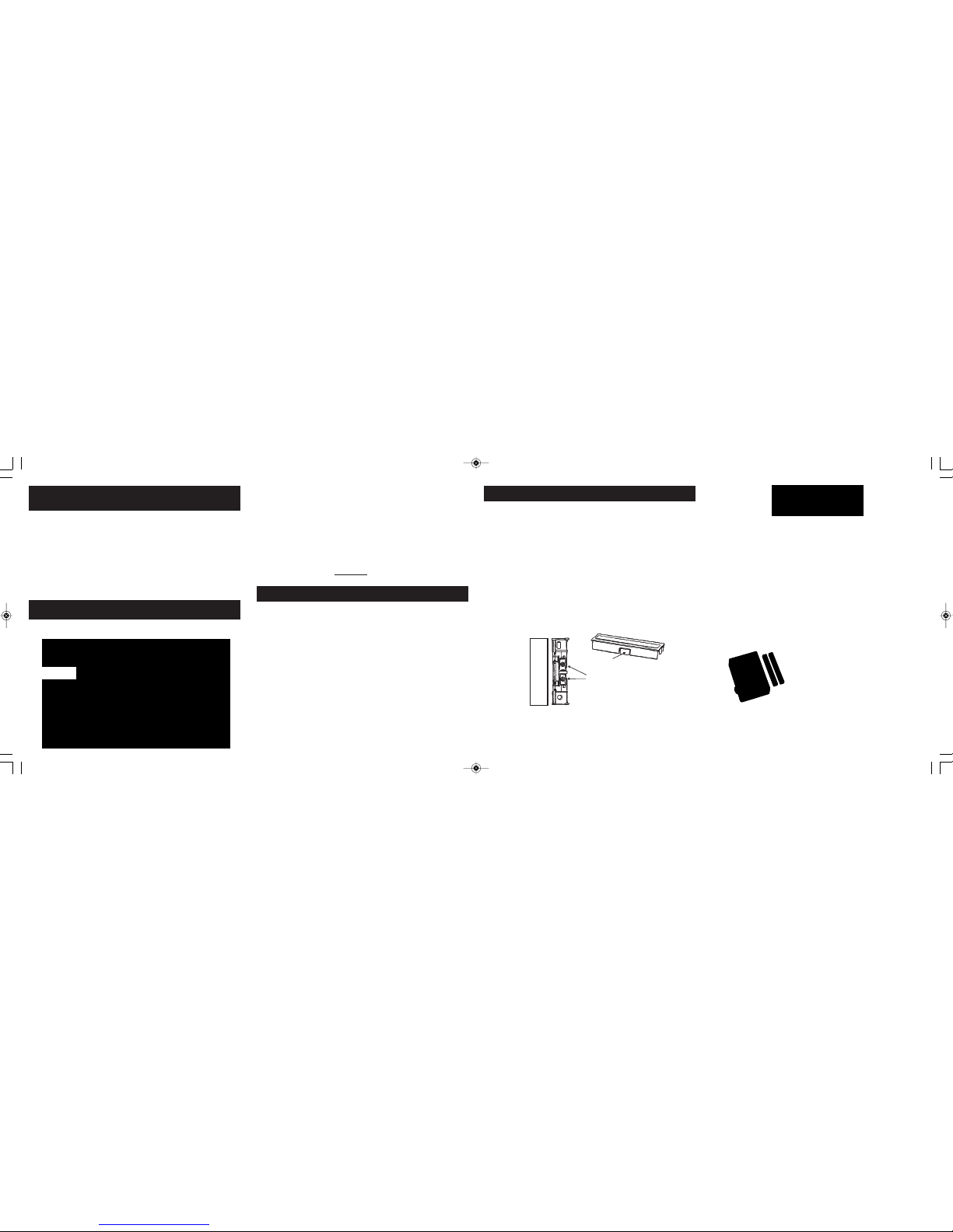
A. The Door Alarm comes with one sensor switch and one sensor
magnet; remove the covers from both of these parts by using your
fingernail or small tool to unclip the cover from the bottom side and
sliding it off the sensor.
B. Each sensor has two holes for mounting, the sensor magnet usually
goes on the door and the sensor switch is usually mounted to the
door frame.
C. Metal framed doors may need a space between the sensors and the
door using a small piece of wood or double sided foam tape.
D. The Sensors must be installed parallel to each other with a spacing
between them of approximately 3/4”. The sensors can be mounted
Horizontally or Vertically as long as they remain parallel.
E. Loosen the two terminals on the sensor switch by loosening the
screws then place either wire end coming from the door alarm
between each of the terminals. It doesn’t matter which wire goes to
which terminal, Replace Plastic Covers.
Note: If the cover for the sensor switch does not lock into place because
of the sensor wires, remove the knockout from the side of the sensor
switch cover (See Figure 4)
3.
OPERATING YOUR DOOR ALARM
(FIG. 1)
4.
Your Poolguard Door Alarm is designed to be installed within 22” of the
sensor switch for the sensor wire connection. To mount the door alarm
on wall next to door:
Figure 2
The POOLGUARD DOOR ALARM uses two delay modes which allow
the user to exit and enter the door without the alarm sounding. These
two modes are explained below.
A. F IRST DELAY MODE: W hen the door is opened the ala rm
automatically goes into the first delay mode which gives you 7
seconds after the door is opened to push the pass thru switch. If the
pass thru switch is not pushed within 7 seconds the alarm will sound
with the door open or closed. To silence the alarm close the door
then push the pass thru switch.
B. SECOND DELAY MODE: When the door is opened and the pass thru
switch is pushed within 7 seconds, this puts the door alarm in the
second delay mode which allows you 14 seconds to go through the
door and close it. When the door is closed within 14 seconds, the
alarm will automatically reset. If the door is not closed within 14
seconds, the alarm will sound.
www.poolguard.com
IN GROUND POOL ALARM
WITH REMOTE RECEIVER
GATE ALARM
Poolguard’s
Family of Products
Helps Protct Your Family!
ABOVE GROUND POOL ALARM
WITH REMOTE RECEIVER
INSTALLING POOLGUARD DOOR ALARM
(FIGS. 1 & 2)
2.
Indoor Use Only
PG DAPT-2 Manual 122208:Layout 1 5/14/09 12:42 PM Page 2
 Loading...