


INSTALLATION
AND
USER MANUAL
for your heat pump
Model Poolex Nano


Thank you
Dear Customer,
Thank you for your purchase and for your condence in our products.
These are the result of many years of research in the eld of design and production
of heat pumps for swimming pools. Our aim is to provide you with an exceptional high
performance quality product.
We have produced this manual with the utmost care so that you get maximum benet
from your Poolex heat pump.

! !
PLEASE READ CAREFULLY
These installation instructions are an integral part of the product.
They must be given to the installer and retained by the user.
If the manual is lost, please consult the website:
www.poolex.fr
The instructions and recommendations contained in this manual should be read carefully and understood
since they provide valuable information concerning the heat pump’s safe handling and operation. Keep this
manual in an accessible place for easy future reference.
Installation must be carried out by a qualied professional person in accordance with current regulations and the manufacturer’s instructions. An installation error may cause physical injury to persons or
animals as well as mechanical damage for which the manufacturer can under no circumstances be held
responsible.
After unpacking the heat pump, please check the contents in order to report any damage. Please
also check that the pressure indicated on the gauge is higher than 80 psi. If not, this could mean a
leak of refrigerant.
Prior to connecting the heat pump, ensure that the information provided in this manual is compatible with
the actual installation conditions and does not exceed the maximum limits authorized for this particular
product.
In the event of a defect and/or malfunction of the heat pump, the electricity supply must be disconnected and no attempt made to repair the fault.
Repairs must be undertaken only by an authorized technical service organization using original replacement parts. Failure to comply with the above-mentioned clauses may have an adverse effect on the heat
pump’s safe operation.
To guarantee the heat pump’s efciency and satisfactory operation, it is important to ensure its regular
maintenance in accordance with the instructions provided.
If the heat pump is sold or transferred, always make sure that all technical documentation is transmitted
with the equipment to the new owner.
This heat pump is designed solely for heating a swimming pool. Any other use must be considered as being
inappropriate, incorrect or even hazardous.
Any contractual or non-contractual liability of the manufacturer/distributor shall be deemed null and void for
damage caused by installation or operational errors, or due to non-compliance with the instructions provided in this manual or with current installation norms applicable to the equipment covered by this document.

Contents
1. General ........................................................................................................................................................................................... 6
1.1 General Terms of Delivery .......................................................................................................................................................... 6
1.2 Safety instructions ...................................................................................................................................................................... 6
1.3 Water treatment ......................................................................................................................................................................... 7
2. Description ..................................................................................................................................................................................... 8
2.1 Package contents ...................................................................................................................................................................... 8
2.2 General characteristics .............................................................................................................................................................. 8
2.3 Technical specications ............................................................................................................................................................. 9
2.4 Unit dimensions ....................................................................................................................................................................... 10
2.5 Exploded view ...........................................................................................................................................................................11
3. Installation ................................................................................................................................................................................... 12
3.1 Location ................................................................................................................................................................................... 12
3.2 Installation layout ..................................................................................................................................................................... 13
3.3 Connecting the condensation draining kit ................................................................................................................................ 13
3.4 Hydraulic connection ................................................................................................................................................................ 14
3.5 Electrical connection ................................................................................................................................................................ 15
4. Use ................................................................................................................................................................................................ 16
4.1 control panel ............................................................................................................................................................................ 16
4.2 Heating Mode ........................................................................................................................................................................... 17
4.3 Status values and advanced settings ...................................................................................................................................... 18
5. Operation ...................................................................................................................................................................................... 20
5.1 Operation ................................................................................................................................................................................. 20
5.3 Using the pressure gauge ........................................................................................................................................................ 21
6. Maintenance and servicing ......................................................................................................................................................... 22
6.1 Maintenance, servicing and winter storage .............................................................................................................................. 22
7. Repairs ......................................................................................................................................................................................... 23
7.1 Breakdowns and faults ............................................................................................................................................................. 23
8. Recycling ...................................................................................................................................................................................... 24
8.1 Recycling the heat pump ......................................................................................................................................................... 24
9. Warranty ....................................................................................................................................................................................... 25
9.1 General warranty conditions .................................................................................................................................................... 25
10. Appendices ................................................................................................................................................................................ 26
10.1 Wiring diagrams ....................................................................................................................................................................... 26

1. General
1.1 General Terms of Delivery
All equipment, even if shipped ‘free of carriage and packing’, is dispatched at the consignee’s own risk.
The person responsible for receiving the equipment must carry out a visual inspection to identify any damage to the heat pump during transport (refrigerant system, body panels, electrical control box, frame). He/
she must note down on the carrier’s delivery note any remarks concerning damage caused during transport
and conrm them to the carrier by registered letter within 48 hours.
The equipment must always be stored and transported vertically on a pallet and in its original packaging. If
it is stored or transported horizontally, wait at least 24 hours before switching it on.
1.2 Safety instructions
WARNING :
The following instructions are essential for safety so please strictly comply with them.
During installation and servicing
Only a qualied person may undertake installation, start-up, servicing and repairs, in compliance with
current standards.
Before operating or undertaking any work on the equipment (installation, commissioning, usage, servicing),
the person responsible must be aware of all the instructions in the heat pump’s installation manual as well
as the technical specications.
Under no circumstances install the equipment close to a source of heat, combustible materials or a building’s air intake.
If installation is not in a location with restricted access, a heat pump protective grille must be tted.
To avoid severe burns, do not walk on pipework during installation, repairs or maintenance.
To avoid severe burns, prior to any work on the refrigerant system, turn off the heat pump and wait several
minutes before placing temperature and pressure sensors.
Please read carefully the safety instructions before using the equipment.
Check the refrigerant level when servicing the heat pump.
Check that the high and low pressure switches are correctly connected to the refrigerant system and that
they turn off the electrical circuit if tripped during the equipment’s annual leakage inspection.
Check that there is no trace of corrosion or oil stains around the refrigerant components.
6

1. General
During use
To avoid serious injuries, never touch the fan when it is operating.
Keep the heat pump out of the reach of children to avoid serious injuries caused by the heat exchanger’s
blades.
Never start the equipment if there is no water in the pool or if the circulating pump is stopped.
Check the water ow rate every month and clean the lter if necessary.
During cleaning
Switch off the equipment’s electricity supply.
Close the water inlet and outlet valves.
Do not insert anything into the air or water intakes or outlets.
Do not rinse the equipment with water.
During repairs
Carry out work on the refrigerant system in accordance with current safety regulations.
Brazing should be performed by a qualied welder.
When replacing a defective refrigerant component, use only parts certied by our technical department.
When replacing pipework, only copper pipes conforming to Standard NF EN12735-1 may be used for
repairs.
When pressure-testing to detect leaks:
To avoid the risks of re or explosion, never use oxygen or dry air.
Use dehydrated nitrogen or a mixture of nitrogen and refrigerant.
The low and high side test pressure must not exceed 42 bar.
1.3 Water treatment
Poolex heat pumps for swimming pools can be used with all types of water treatment systems.
Nevertheless, it is essential that the treatment system (chlorine, pH, bromine and/or salt chlorinator metering pumps) is installed after the heat pump in the hydraulic circuit.
To avoid any deterioration to the heat pump, the water’s pH must be maintained between 6.9 and
8.0.
7

2. Description
2.1 Package contents
✔ Heat pump Poolex Nano
✔ 2 hydraulic inlet/outlet connectors 32/38mm diameter
✔ This installation and user manual
✔ Condensation draining kit
✔ 4 anti-vibration pads
2.2 General characteristics
A Poolex heat pump has the following features:
CE certication and complies with the RoHS European directive.
High performance with up to 80% energy savings compared to a conventional heating system.
Clean, efcient and environmentally friendly R410A refrigerant.
Reliable high output leading brand compressor.
Wide hydrophilic aluminum evaporator for use at low temperatures.
User-friendly intuitive control panel.
Heavy duty shell, anti-UV treated and easy to maintain.
Designed to be silent.
8

2. Description
2.3 Technical specications
Nano
Heating power (W) 2800
(1)
Air
26°C
Consumption (W) 530
(2)
Water
26°C
COP (Coeff. of performance) 5,3
Heating power (W) 2200
(1)
Air
15°C
Consumption (W) 510
(2)
Water
26°C
COP (Coeff. of performance) 4,3
Electricity supply 220-240V single-phase ~ 50Hz
Maximum power (W) 810
Maximum current (A) 3.62
Heating temperature range 15°C~40°C
Operating range 7°C~43°C
Unit dimensions L × W × H (mm) 385 x 400 x 280
Unit weight (kg) 15
Packaging dimensions L × W × H (mm) 415 x 460 x 380
Packaging weight (kg) 17
Sound pressure level at 10 m (dBA)
Hydraulic connection (mm) PVC 32 / 38mm
Heat exchanger PVC tank and titanium heating coil
Min. water ow rate (m³/h) 1,3
Compressor Toshiba
Compressor type Rotary
Refrigerant R410A
Refrigerant content (kg) 0,3
GWP 2088
Equivalent CO2 0,63
Waterproof IP IPX4
Load loss (mCE) 0,8
Max. pool volume (m3)
(4)
Control panel Backlight LCD screen
Mode Heating
(3)
<28
≤20
The technical specications of our heat pumps are provided for information purposes only. We reserve the right to make changes without prior notice.
1
Ambient air temperature
2
Initial water temperature
3
Noise at 10 m in accordance with Directives EN ISO 3741 and EN ISO 354
4
Calculated for an in-ground private swimming pool covered with a bubble cover.
9

2.4 Unit dimensions
2. Description
A
E
D
B
比例 1.000
C
Nano
A 385
B 400
C 280
D 55
E 140
10
Dimensions in mm

2.5 Exploded view
2. Description
5
6
7
8
9
10
11
12
13
14
4
3
2
1
15
16
1. Base plate
2. Compressor
3. Evaporator
4. Top panel
5. Throttling parts
6. Electrical control box
7. Flow switch
8. Pressure gauge
9. Left side panel
10. Heat exchanger
11. Fan and motor
12. Fan support
13. Control panel cover
14. Control panel
15. Front panel
16. Fan protective grill
11

3. Installation
The heat pump is very easy to install, only water and power need to be connected during
installation.
3.1 Location
The heat pump should be located at least 2.5 meter away from the swimming pool.
>2.5m
Pool
Please comply with the following rules concerning the choice of heat pump location.
1. The unit’s future location must be easily accessible for convenient operation and maintenance.
2. It must be installed on the ground, laid ideally on a level concrete oor. Ensure that the oor is sufciently
stable and can support the weight of the unit.
3. A water drainage device must be provided close to the unit in order to protect the area where it is installed.
4. Check that the unit is properly ventilated, that the air outlet is not facing the windows of neighboring
buildings and that the exhaust air cannot return. In addition, provide sufcient space around the unit for
servicing and maintenance operations.
5. The unit must not be installed in an area exposed to oil, ammable gases, corrosive products, sulfurous
compounds or close to high frequency equipment.
6. To prevent mud splashes, do not install the unit near a road or track.
7. To avoid causing nuisance to neighbors, make sure the unit is installed so that it is positioned towards the
area that is least sensitive to noise.
8. Keep the unit as much as possible out of the reach of children.
≥1500
Place nothing less than 1,50 m in front of the heat pump.
Leave 30 cm cm of empty space around the sides and rear of the heat pump.
Do not leave any obstacle above or in front of the unit!
12
≥300
≥300
Dimensions in mm

3.2 Installation layout
POOL
3. Installation
TOWARDS THE POOL
Automated treatment
system
Filtration + Pump
FROM THE POOL
The lter located upstream of the heat pump must be regularly cleared so that the water in
the system is clean, thus avoiding the operational problems associated with dirt or clog-
ging in the lter.
3.3 Connecting the condensation draining kit
While operating, the heat pump is subject to condensation. This will result in a more or less large run-off
of water, depending on the degree of humidity. To channel this ow, we recommend that you install the
condensation drainage kit.
13

3. Installation
3.4 Hydraulic connection
Step 1 : Screw the connectors to the heat pump
Step 2 : Connect the water outlet pipe and the water intake pipe
TOWARDS THE POOL
FROM THE POOL
14

3. Installation
3.5 Electrical connection
The heat pump electrical plug integrates a 10mA differential circuit breaker.
Before connecting your heat pump, please ensure that the plug is connected to the ground.
The lter pump should function at the same time as the heat pump. Therefore, you need to connect them to
the same electrical circuit.
15

4. Use
4.1 Control panel
1. ON/OFF 2. Heating 3. Malfunction 4. Defrost 5. Fan
6. Water pump 7. Compressor 8. Setting 9. + 10. -
16

4. Use
4.2 Heating Mode
WARNING: Before starting, ensure that the ltration pump is operating correctly.
Step 1 : Press to switch on your pump.
Step 2 : Using buttons and select the required temperature.
EXAMPLE:
If the current temperature is 15°C, default setting temperature is 27° required temperature is 30°C.
Current water
temperature
Useful information about how the heating mode operates
Required
temperature
When the incoming water temperature is less than or equal to the required temperature (setpoint temperature) -X°C, the heat pump will switch to heating mode. The compressor will stop when the temperature of
the incoming water is greater than or equal to the required temperature (setpoint temperature).
Indicators for adjustment range X and Y
X : adjustable parameter from 1° to 15°C, default setting is 3°C. (Parameter N°6)
17

4. Use
4.3 Status values and advanced settings
WARNING: This operation is used to assist servicing and future repairs.
The default settings should only be modied by an experienced professional person.
The system’s settings can be checked and adjusted via the remote control by following these steps
Step 1 : Keep pressing until you enter the settings verication mode.
Step 2 : Press and for see the parameters.
Step 3 : Press to select the setting to be modied.
Note, some settings cannot be modied. Consult the settings table for further information.
Step 4 : Press and to adjust the setting value.
Step 5 : Press to set the new value.
Step 6 : Press to return to the main screen.
Value 30 Parameter N°5
18
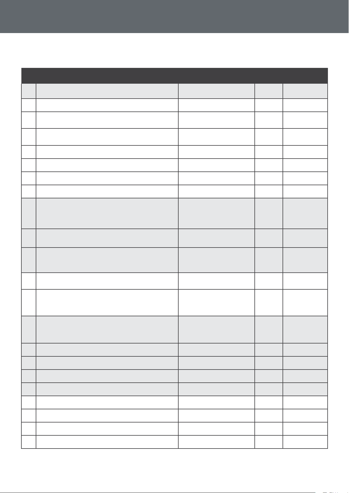
Parameters table
4. Use
N° Description Adjustment range
0
Reserved - Do not adjust 8~37°C 12°C Reserved
1
Default temperature 15~40°C 27°C Adjustable
2
Defrost auto-activation time 10~90 min 40 min Adjustable
3
Defrost activation temperature -30~0°C 0°C Adjustable
4
Defrost deactivation temperature 1~30°C 2°C Adjustable
5
Maximum defrost duration 10~40 min 30 min Adjustable
6
Adjustment of temperature difference for restart 2~10°C 3°C Adjustable
7
Automatic restart
8
Reserved - Do not adjust 0 / 1 / 2 0 Reserved
9
Reserved - Do not adjust 0 / 1 0 Reserved
0 = OFF
1 = ON
Factory
setting
1 Adjustable
Remarks
A
Reserved - Do not adjust 8~60°C 30°C Reserved
B
Antifreeze protection - low air temperature 0~15°C 8°C Ajustable
C
Antifreeze protection - low water temperature 2~14°C 4°C Ajustable
D
Reserved - Do not adjust - - Reserved
E
Reserved - Do not adjust 0 / 1 0 Reserved
F
Reserved - Do not adjust 3~20°C 5°C Reserved
H
Reserved - Do not adjust 5~20°C 13°C Reserved
J
Reserved - Do not adjust 65~90°C 70°C Reserved
o
Water intake temperature -9~99°C Actual data
P
Water outlet temperature -9~99°C Actual data
t
Coil temperature -9~99°C Actual data
U
Ambient air temperature -9~99°C Actual data
19

5. Operation
5.1 Operation
Conditions of use
For the heat pump to operate normally, the ambient air temperature must be between 7°C and 43°C.
Recommendations prior to start-up
Before activating the heat pump, please:
✔ Check that the unit is stable.
✔ Check that the gauge indicates a pressure greater than 80 psi.
✔ Control the proper functioning of your electrical installation.
✔ Check that the hydraulic connections are tight and that there is no leakage of water.
✔ Remove any unnecessary object or tool from around the unit.
Operation
1. Connect the unit power plug.
2. Activate the circulating pump.
3. Activate the unit’s power supply protection (differential switch and circuit-breaker).
4. Activate the heat pump by pressing once on .
5. Select the required temperature.
6. The heat pump’s compressor will start up after a few moments.
All you have to do now is wait until the required temperature is reached.
WARNING: Under normal conditions, a suitable heat pump can heat the water in a swimming
pool by 1°C to 2°C per day. It is therefore quite normal to not feel any temperature difference in
the system when the heat pump is working.
A heated pool must be covered to avoid any loss of heat.
20

5. Operation
5.2 Using the pressure gauge
The gauge is for monitoring the pressure of the refrigerant contained in the heat pump.
The values it indicates can vary considerably, depending on the climate, temperature and atmospheric
pressure.
When the heat pump is in operation:
The gauge needle indicates the refrigerant pressure.
Mean operating range between 120 and 400 PSI, depending on the ambient temperature and atmospheric
pressure.
When the heat pump is shut down:
The needle indicates the same value as the ambient temperature (within a few degrees) and the corresponding atmospheric pressure (between 150 and 350 PSI maximum).
If left unused for a long period of time :
Check the pressure gauge before starting up the heat pump. It must indicate at least 80 PSI.
If the pressure goes down too much, the heat pump will display an error message and automatically go into
‘safe’ mode.
This means that there has been a leakage of refrigerant and that you must call a qualied technician to
replace it.
21

6. Maintenance and servicing
6.1 Maintenance, servicing and winter storage
WARNING: Before undertaking maintenance work on the unit, ensure that you have
disconnected the electrical power supply.
Cleaning
The heat pump’s casing must be cleaned with a damp cloth. The use of detergents or other household
products could damage the surface of the casing and affect its properties.
The evaporator at the rear of the heat pump must be carefully cleaned with a vacuum cleaner and soft
brush attachment.
Annual maintenance
The following operations must be undertaken by a qualied person at least once a year.
✔ Carry out safety checks.
✔ Check the integrity of the electrical wiring.
✔ Check the earthing connections.
✔ Monitor the state of the pressure gauge and the presence of refrigerant.
Winter storage
Your heat pump is designed to operate in rainy weather conditions and withstand frost using a specially
created anti-frost technology. However it is not recommended to leave it outside for long periods of time (eg
over winter). After draining down the pool for the winter, store the heat pump in a dry place.
22

7. Repairs
WARNING: Under normal conditions, a suitable heat pump can heat the water in a swimming
pool by 1°C to 2°C per day. It is therefore quite normal to not feel any temperature difference in
the system when the heat pump is working.
A heated pool must be covered to avoid any loss of heat.
7.1 Breakdowns and faults
In the event of a problem, the heat pump’s screen displays a fault symbol instead of temperature indica-
tions. Please consult the table below to nd the possible causes of a fault and the actions to be taken.
Code Fault Possible causes Action
Sensor badly connected Reconnect sensor
Water intake temperature sensor malfunction
P1
Water outlet temperature sensor malfunction
P2
Evaporator temperature sensor malfunction
P3
External temperature sensor malfunction
P5
Antifreeze protection
P7
High pressure protection
E1
Low pressure protection
E6
Flow sensor malfunction
E3
Sensor defective Replace sensor
Defective control panel Replace control panel
Same causes as P1 Same actions as P1
Protection activated when the ambient temperature
is too low.
Insufcient water ow Check water pump operation
Pressure switch disconnected or defective Reconnect or replace pressure switch
Defective control panel Replace control panel
Insufcient refrigerant Readjust the quantity of refrigerant
Pressure switch disconnected or defective Reconnect or replace pressure switch
Defective control panel Replace control panel
Insufcient water in heat exchanger Check your water circuit operation
Defective water ow sensor Replace water ow switch
Defective control panel Replace control panel
No intervention is necessary
Excessive difference between water inlet temperature and
P8
water outlet temperature
Water ow rate too low Check water pump and hydraulic system operation
Defective control panel Replace control panel
23

8. Recycling
8.1 Recycling the heat pump
Your heat pump has reached the end of its life and you wish to dispose of it or to replace it. Do not throw it
in the rubbish bin.
A heat pump must be disposed of separately with a view to its reuse, recycling or upgrading. It contains
substances that are potentially hazardous to the environment but which will be eliminated or neutralized by
recycling.
YOU HAVE THREE SOLUTIONS:
1 2
Disposing of it at your local
recycling centre
Giving it to a social service
organisation for it to be
repaired and put back into
circulation.
3
Returning it to the heat pump
distributor against a new
purchase.
24

9. Warranty
9.1 General warranty conditions
The Poolstar Company guarantees the original owner against defective materials and faults in the manufacture of the Poolex Nano heat pump for a period of two (2) years.
The compressor is guaranteed for a period of ve (5) years.
The titanium tube heat exchanger has a period of ten (10) years guarantee against chemical corrosion,
except for frost damage.
The condenser’s other components are guaranteed for two (2) years.
The warranty becomes effective on the date of the rst invoice.
The warranty does not apply in the following cases:
• Malfunction or damage arising from an installation, usage or repair that is not in compliance with the
safety instructions.
• Malfunction or damage arising from a chemical agent that is unsuitable for the pool.
• Malfunction or damage arising from conditions that are unsuitable for the equipment’s purposes of use.
• Damage arising from negligence, accident or force majeure.
• Malfunction or damage arising from the use of unauthorized accessories.
Repairs undertaken during the warranty period must be approved prior to being carried out by an authorized
technician. The warranty shall be null and void if the repair to the equipment is carried out by a person who
is not authorized by the Poolstar company.
The guaranteed parts shall be replaced or repaired at Poolstar’s discretion. Defective parts must be returned
to our workshops to be covered during the warranty period. The warranty does not cover labor costs or
unauthorized replacements. The return of the defective part is not covered by the warranty.
Dear Sir/Madam,
Please spend a few minutes lling in the warranty registration card
that you will nd on our website:
http://support.poolex.fr/
We thank you for your trust in our products.
Enjoy your swimming!
Your details may be treated in accordance with the Data Protection Act of
6 January 1978 and will not be divulged to any third party.
WARNING:
The contractual warranty cannot be validated with the installer or Poolstar unless your prod-
uct has been registered on our website.
25

10.1 Wiring diagrams
10. Appendices
26

27

TECHNICAL SUPPORT
www.poolex.fr
Poolex is a Poolstar Group trademark
www.poolstar.fr
Issued 01-2018
 Loading...