

Pool Check 481700-K, Pool Check i, Pool Check i Pro 3, Pool Check i Pro 6 Instruction Manual
Page 1
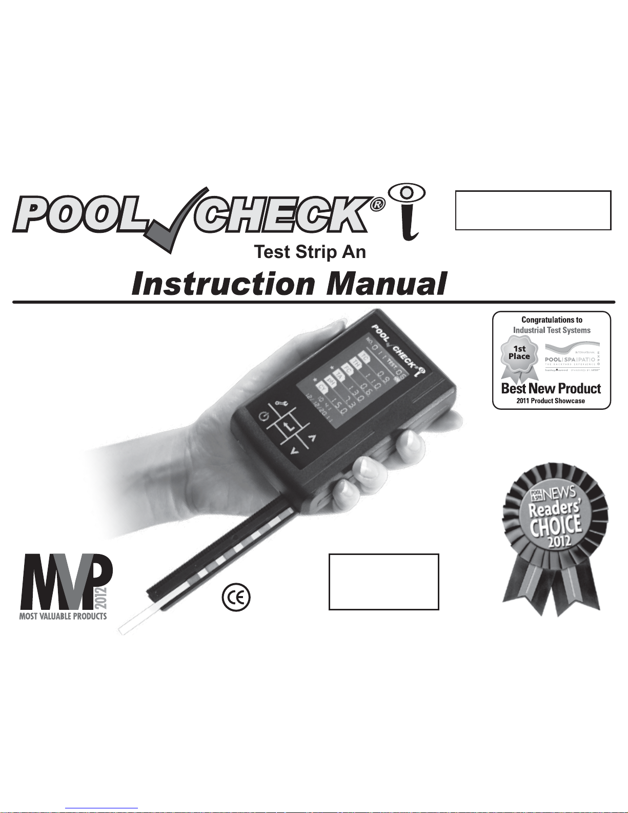
Revision 06/04/12
Kit Part #481700-K
Digital Test Strip Analyzer
Pool Check®i
is Manufactured
and tested in an
ISO 9001 Facility
Page 2

Manufactured By: Industrial Test Systems, Inc.
1875 Langston Street, Rock Hill, SC 29730 USA
Phone: 1-800-861-9712 - INSIDE THE U.S.
1-803-329-9712 - OUTSIDE THE U.S.
Fax: 1-803-329-9743
[email protected]
POOLCHECKONLINE.COM
SENSAFE.COM
©2012 Industrial Test Systems, Inc.
POOL CHECK
®
is a registered trademark of
Industrial Test Systems, Inc., Rock Hill, SC USA
Pool Check® i Analyzer (bulk) . . . . . . . . . . #481700
Pool Check
®
i Analyzer (kit) . . . . . . . . . . . #481700-K
Pool Check
®
i Analyzer (case of 10 kits) . #481700-K-10
Pool Check
®
i Pro 3, B100 (loose). . . . . . . #481703
Pool Check
®
i Pro 3, B100 (case of 6) . . . #481703-6
Pool Check
®
i Pro 6, B100 (loose). . . . . . . #481706
Pool Check
®
i Pro 6, B100 (case of 6) . . . #481706-6
Pool Check
®
i Pro 6 Control Strip . . . . . . . #481702
Pool Check®i Reorder Information
Page 3
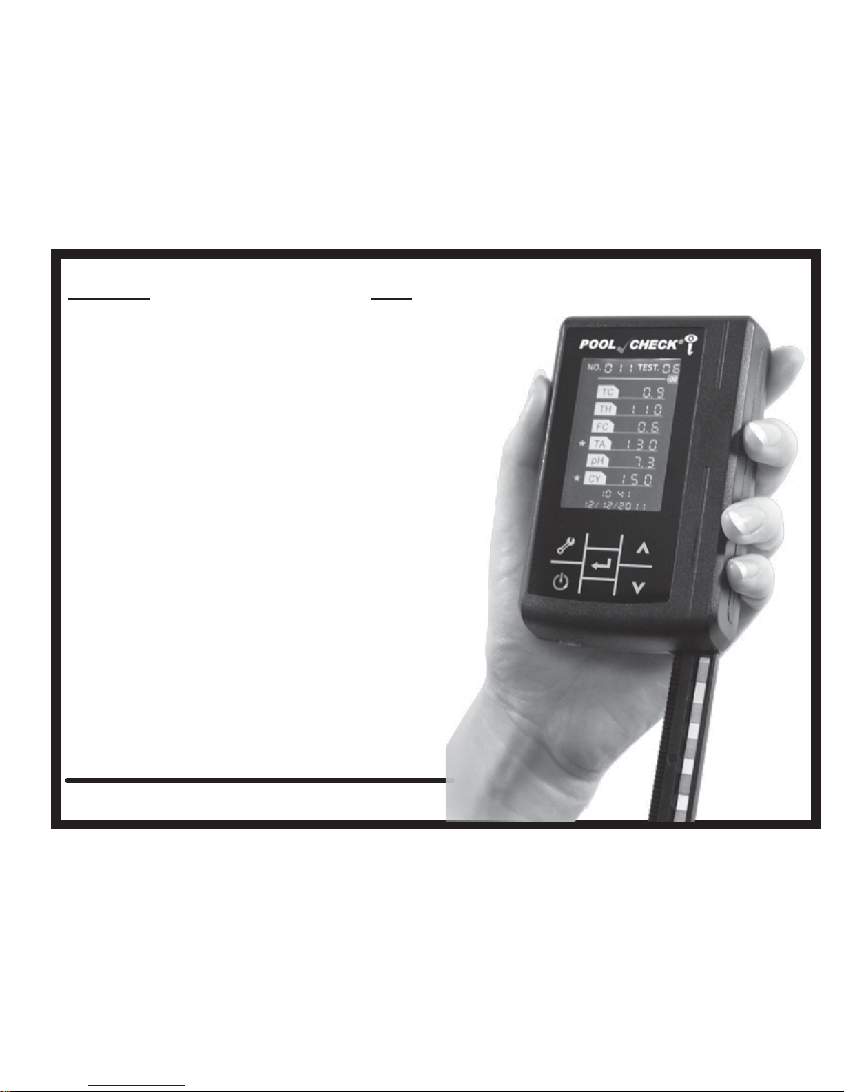
Index:
Contents: Page
Specifications . . . . . . . . . . . . . . . . . . 4-5
Foreword . . . . . . . . . . . . . . . . . . . . . . 6
Features . . . . . . . . . . . . . . . . . . . . . . . 7
Kit Components. . . . . . . . . . . . . . . . . 8
Instrument Operation . . . . . . . . . . . . 9
Display Explanation . . . . . . . . . . . . . 10
Power On Self-Test (POST). . . . . . . . 11-12
Test Procedure. . . . . . . . . . . . . . . . . . 13-16
Data Query/Upload . . . . . . . . . . . . . . 17
Delete All Data . . . . . . . . . . . . . . . . . . 18
Adjust Sensitivity Setting . . . . . . . . . 19
Set Time and Date . . . . . . . . . . . . . . . 20
Test Configuration. . . . . . . . . . . . . . . 21
Control Strip Procedure . . . . . . . . . . 22
Troubleshooting/Error Codes. . . . . . 23
Tips for Best Results. . . . . . . . . . . . . 24
Instrument Cleaning . . . . . . . . . . . . . 25
Battery Charging . . . . . . . . . . . . . . . . 25
Instrument Maintenance . . . . . . . . . . 26
Packing, Storage, Transportation . . 26
Limited Warranty. . . . . . . . . . . . . . . . 27
Contact Information . . . . . . . . . . . . . 28
Visit us online at poolcheckonline.com
for up-to-date product information.
Page 4
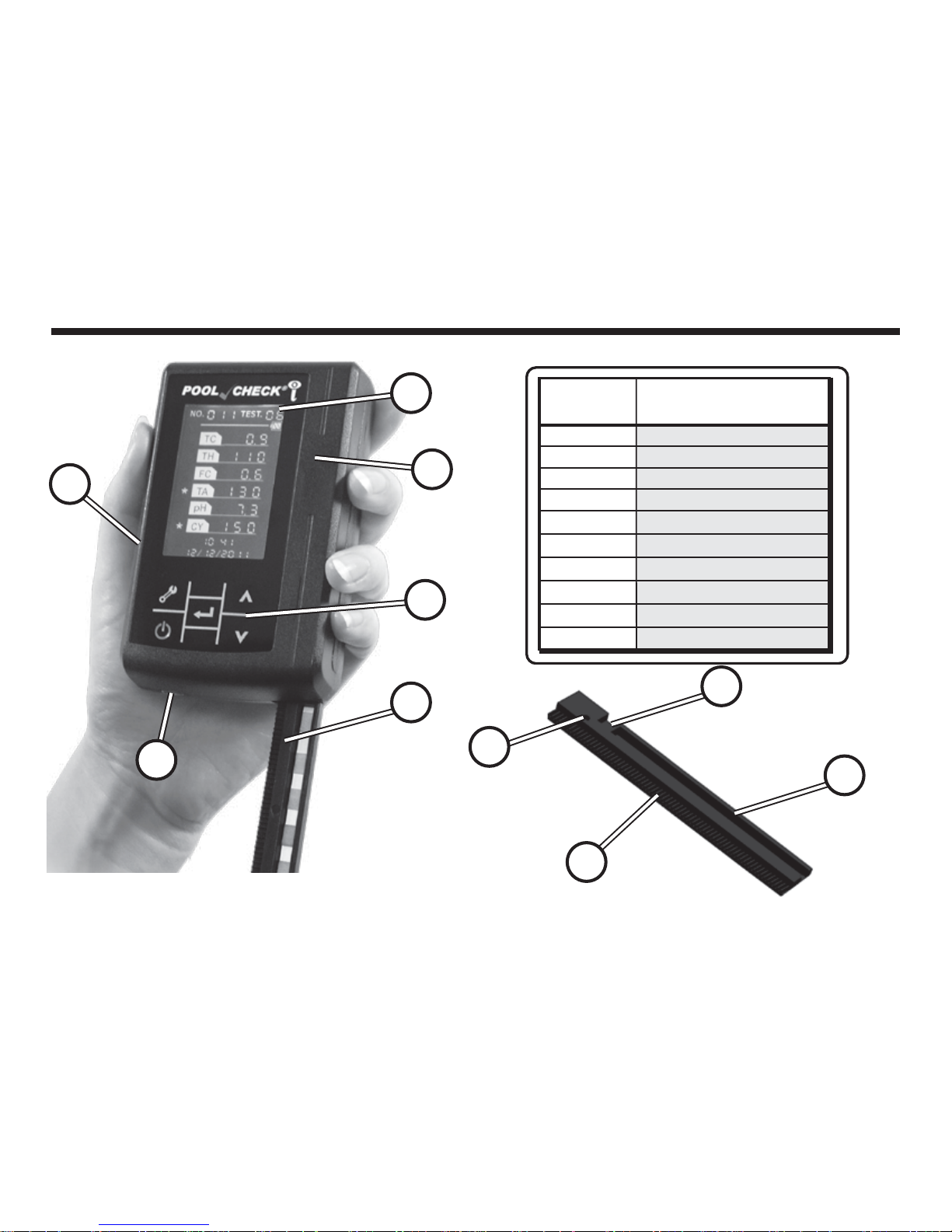
Pool Check®i Digital Analyzer
E
F
D
C
B
A
ITEM PICTURED
LETTER
COMPONENT
NAME
A
LCD Display
B
Cover
C
Reset Slot (Hole on Back Side)
D
Capacitive Touch Keys
E
Strip Track (Plastic)
F
Mini USB interface
G
Home Sensor (Metal Dot)
H
White Calibration Pad
I
Gear Track
J
Test Strip Slot
H
G
I
J
4
Page 5
Instrument Weight: 160g
Instrument Dimensions: 68 (W) x 100 (D) x 27 (H) mm;
(2.68 x 3.94 x 1.06 in)
Recommended Temp: 0 - 50°C (32° - 122°F)
Operating Limits: Humidity: below 80%
Pressure: 86KPa–106KPa
Keep away from strong electric
(magnetic) field
Avoid direct sunlight
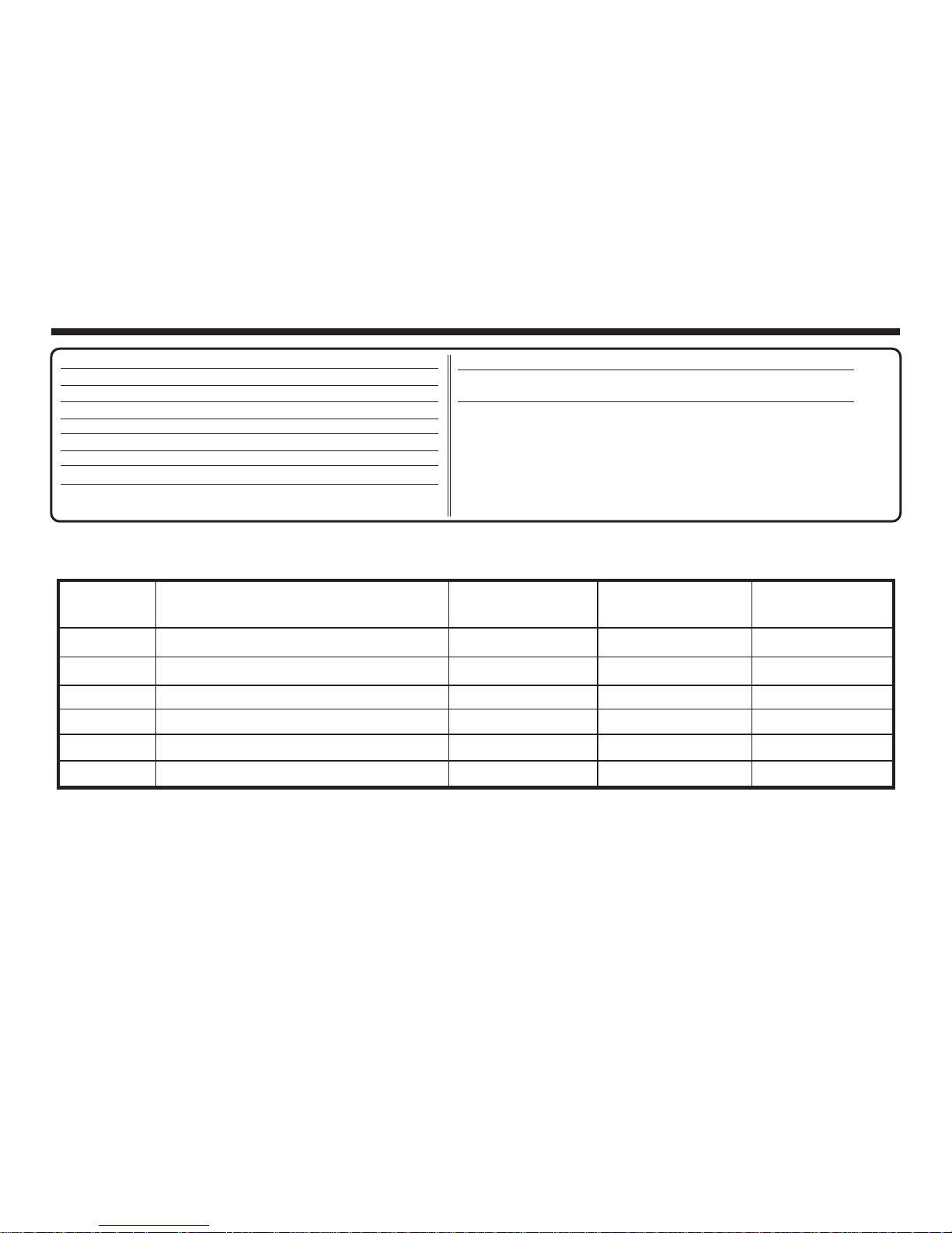
Pool Check®i Digital Analyzer Technical Specifications
Test Principle: Light Reflectance
Light Source: Light Emitting Diode (LED)
Display: Liquid Crystal Display
Keys: Capacitive Touch Keys
Throughput: 60 samples/hour
Host Power:
DC 5V, 2A
Adapter Power:
AC 110V, 50/60Hz
Battery Type:
Built-in 1000mA rechargeable lithium
Instrument Life:
Up to 100,000 tests under normal
care and with proper use
Pool Check®i Digital Analyzer Test Range
R060412
TC
TH
FC
TA
PH
CY
Total Chlorine/Total Bromine
†
Total Hardness
Free Chlorine/Free Bromine*
Total Alkalinity*
pH*
Cyanuric Acid
0 - 50 ppm
0 - 1000 ppm
0 - 50 ppm
0 - 360 ppm
6.0 - 9.0 ph
0 - 500 ppm
±22%
±25%
±22%
±26%
±0.5 pH
±30%
0.1 / 1 / 5
5 / 30 / 50
0.1 / 1 / 5
5 / 20
0.1
20 / 50
Code Tests for Range Resolution Accuracy
*These tests are used for the Pool Check®i Pro 3 test strips.
Parameters calibrated at 28°C (82°F), 100-120 ppm Total Alkalinity.
pH and CY values will be over 50% low when TA is below 60 ppm and over 50% high when TA is above 170 ppm.
Accuracy reported for the average of a minimum of 6 replicates.
Best accuracy for Free and Total Chlorine above 1 ppm.
6SHFL¿FDWLRQVVXEMHFWWRFKDQJHZLWKRXWQRWLFH
†
Multiply Total Chlorine value by 2 for Total Bromine value.
5
Page 6

Foreword
Thank you for purchasing the Pool Check®i digital analyzer. For best results please read
this manual before using the Pool Check
®
i. To keep up with revisions in the manual, ITS
suggests that you visit our website: www.PoolCheckOnline.com
The Pool Check
®
i is equipped with data storage capability, but ITS takes no responsibility
for data loss caused by device damage or improper operation. Opening the housing of the
Pool Check
®
i by anyone other than ITS service department will void all warranty or
after-sale service.
Warning
For best results the Pool Check®i should only be operated after reading this manual and
viewing the operation procedure video on our website: www.PoolCheckOnline.com. The
Pool Check
®
i has a calibration procedure using the SEN setting that must be completed
when using a new lot of Pool Check
®
i Pro 6 Test Strips or when switching to the Pool
Check
®
i Pro 3 Test Strips. Not completing this step can lead to inaccurate results.
The Pool Check
®
i is not waterproof, but is designed to be water resistant. Be careful that
the unit does not fall into the Pool or Spa.
The Pool Check
®
i is a precision instrument; do not drop or expose to chemicals. Avoid
leaving the unit in direct sunlight for long periods of time.
6
Page 7
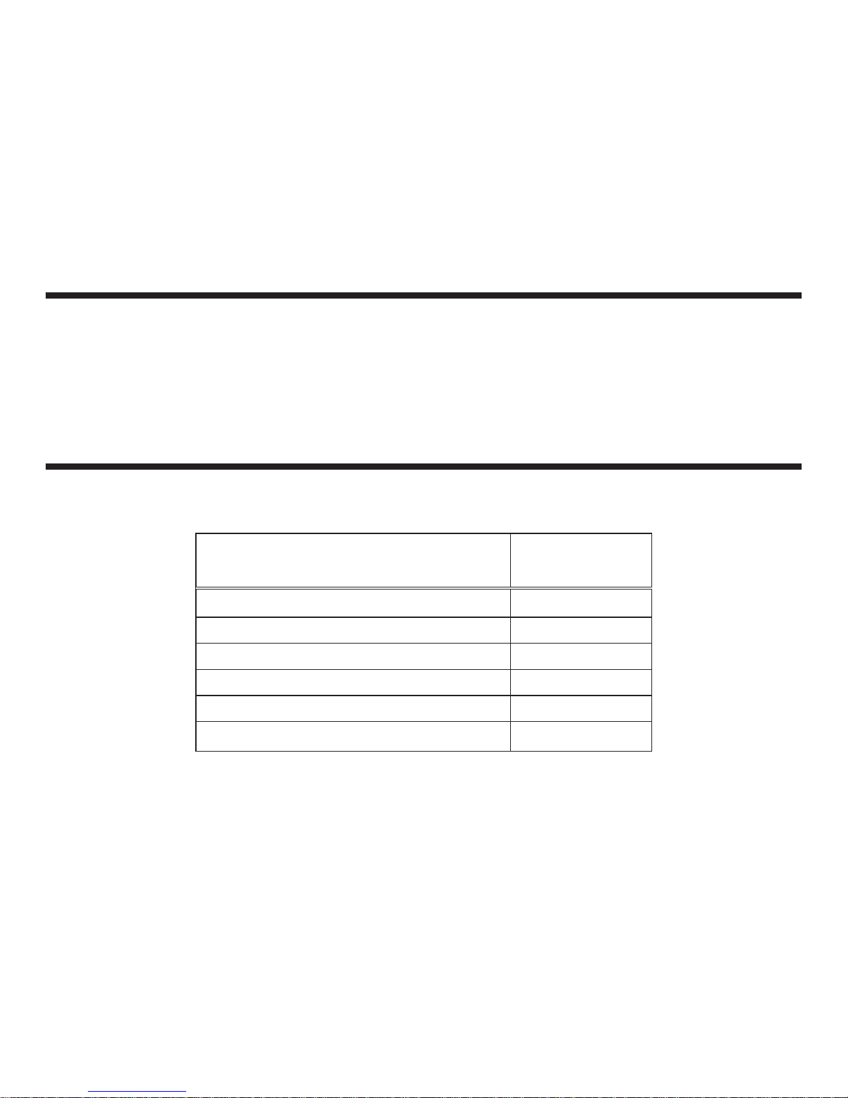
Pool Check®i
Designation
Total Chlorine/Total Bromine*
Total Hardness
Free Chlorine/Free Bromine*
Total Alkalinity
pH
Cyanuric Acid
TC
TH
FC
TA
pH
CY
Test Description
Pool Check®i Digital Analyzer Features
• Precision analyzer for field or in-store testing.
• 3 or 6 parameter test strips.
• Capacitive touch keys.
• High Quality 1000mA rechargeable lithium battery.
• Fast and reliable test procedure.
Product Application Scope
This device can be used for testing swimming pool or spa water quality. The Pool Check®i
can be used with Pool Check
®
i Pro 3 or Pool Check®i Pro 6 Test Strips for testing these
parameters:
*When testing a Bromine system, the Bromine values can be
determined by multiplying the TC result by 2.2.
7
Page 8

Kit Components
Open the sturdy aluminum carrying case and verify the contents:
1. Pool Check
®
i Digital Analyzer
2. Instruction Booklet
3. 3 Power Cords
a. 110 VAC USB Power Adaptor
b. Mini-USB to 9-pin Serial Computer Cable
c. Mini-USB to USB Cable
4. Bottle of Pool Check
®
i Pro 3 or Pool Check®i Pro 6 Test Strips
5. Control Test Strip
6. Plastic Sampling Tube
Remove the Pool Check
®
i and check the appearance of the instrument. Connect the AC
power to the instrument. Once the cable is connected, the battery will recharge within 4
hours.
If you have any questions, please contact Tech Support at (803) 329-9712 x226. Please
register your meter online at www.PoolCheckOnline.com to assure that your purchase is
properly registered for warranty coverage. Visit the website for updates on software,
procedures and specifications for your Pool Check
®
i.
NOTICE: Please do not store unit above a temperature of 86°F / 30°C and humidity of
80%, avoid corrosive gases (hydrochloric acid and chlorine tablets or liquids), dust,
and strong electromagnetic environments.
8
Page 9
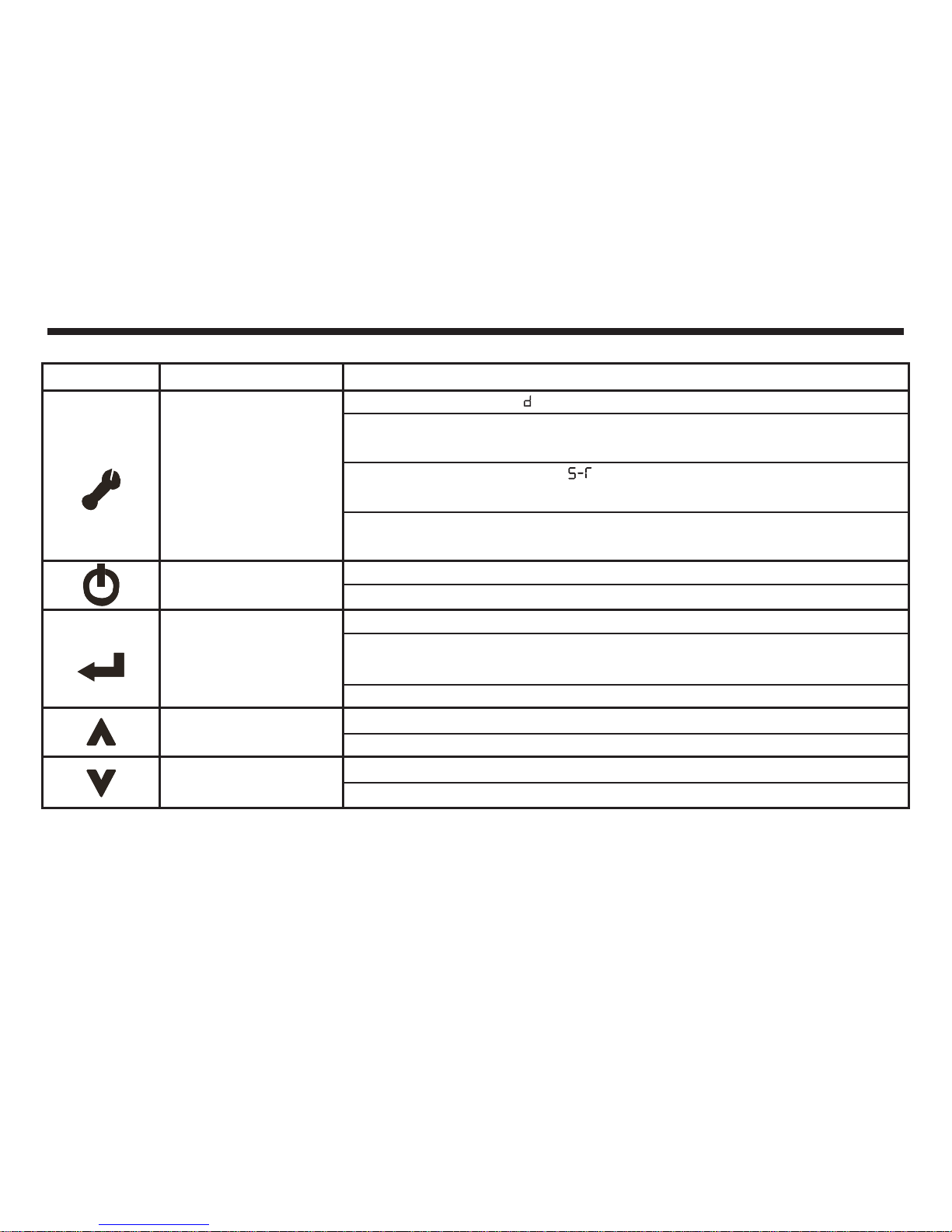
Instrument Operation
Key Function
Tool (Set-up) Function
Main
Confirm
Up
Down
Operation
Press once to enter the EL “delete all data” function.
Press again to enter the SEN “sensitivity setting” function that allows
for calibration of the Pool Check®i to a new lot of Test Strips.
Press a third time to enter the “date and time configuration” function
that allows for the date and time to be set.
Press a fourth time to enter the S-P “test configuration” function to select
whether you are using Pool Check®i Pro 3 or Pool Check®i Pro 6 Test Strips.
Long press, ON/OFF.
Short press, exit Tool (Set-up) Function or to interrupt test.
Short press in the main interface to start the 35 second countdown.
Long press during 35 second countdown bypasses the countdown and
starts analysis of the Test Strip.
Short press to navigate in other interfaces.
Short press; number increases in 1 increment
Long press; number increases rapidly (continuously)
Short press; number decreases in 1 increment
Long press; number decreases rapidly (continuously)
9
Page 10
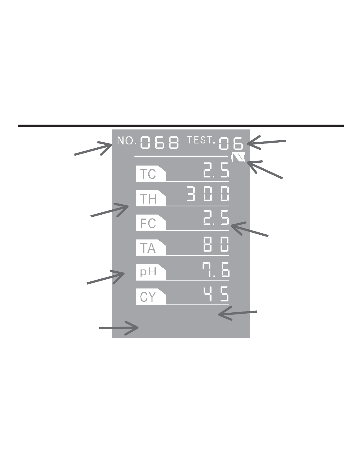
13:54
03/30/2012
Display Explanation
Test
Type
Battery
Indicator
Test
Results
Date
(MM/DD/YY)
Time
(24 hour)
Test
Parameter
Out-of-Range
Indicator
Sample
Number
*
10
Page 11
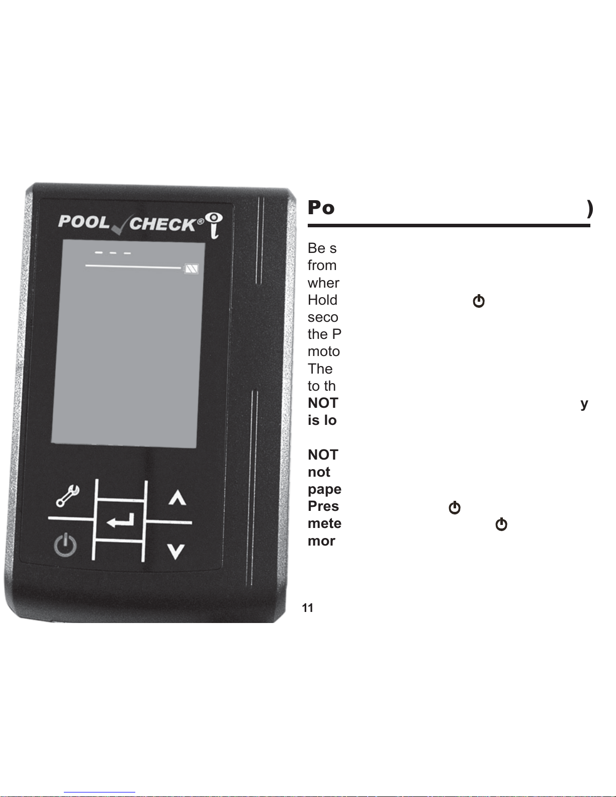
Power On Self-Test (POST)
Be sure that the meter has been removed
from the carrying case and is positioned
where the Strip Track has room to extend.
Hold down the Main key ( ) for about 2
seconds. The power LED will light up, and
the POST interface will be displayed. The
motor will start and extend the Strip Track.
The POST interface will appear as shown
to the left.
NOTE: Instrument will not boot if battery
is low. Battery must be recharged.
NOTE: If the meter is charged and will
not power on, insert a straightened
paper clip in the RESET slot and press.
Press the Main key ( ) to turn on the
meter. Press the Main key ( ) once
more to return to the main interface.
11
Page 12
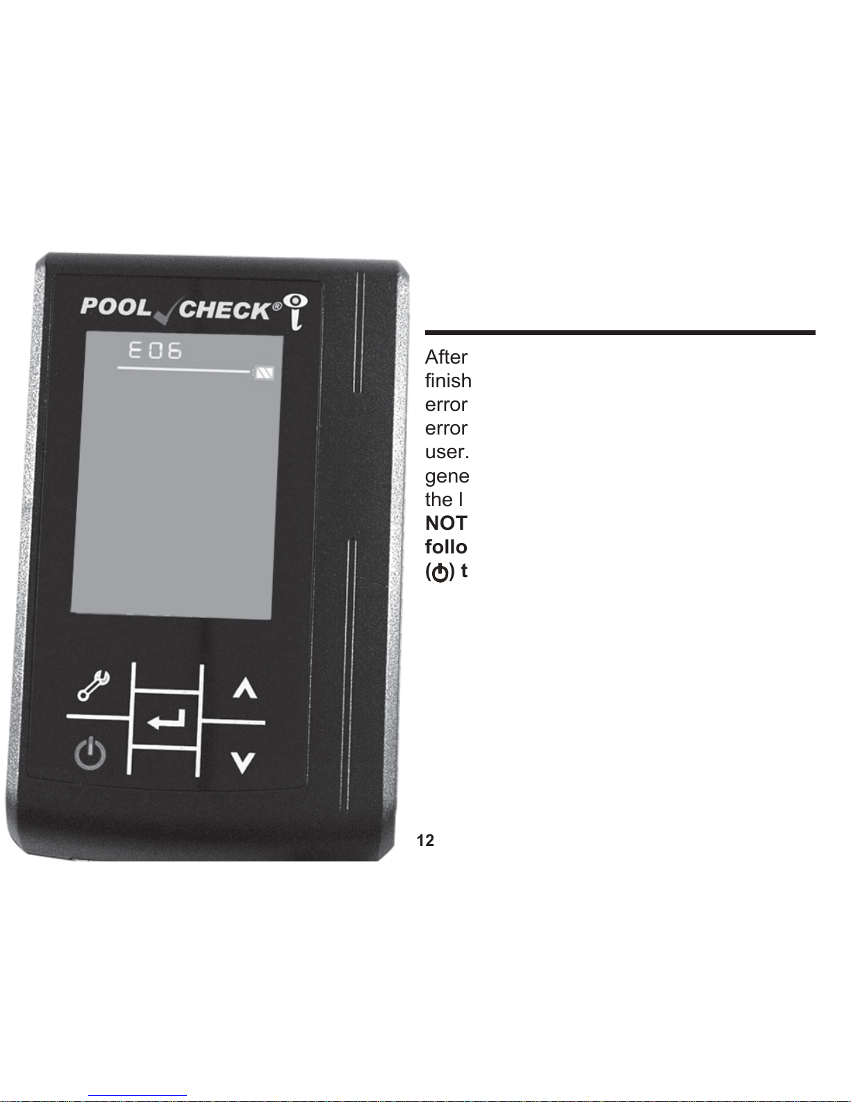
After the Power On Self-Test (POST)
finishes, a code will appear if there is an
error (see Error Codes on page 23). The
error code blinks to bring attention to the
user. At the same time, the instrument will
generate a “DING” sound. In the image to
the left, the error code is 06.
NOTICE: If an error code is shown
following the POST, press the Main key
( ) to exit the error menu.
12
Power On Self-Test
(POST) (
Continued)
Page 13
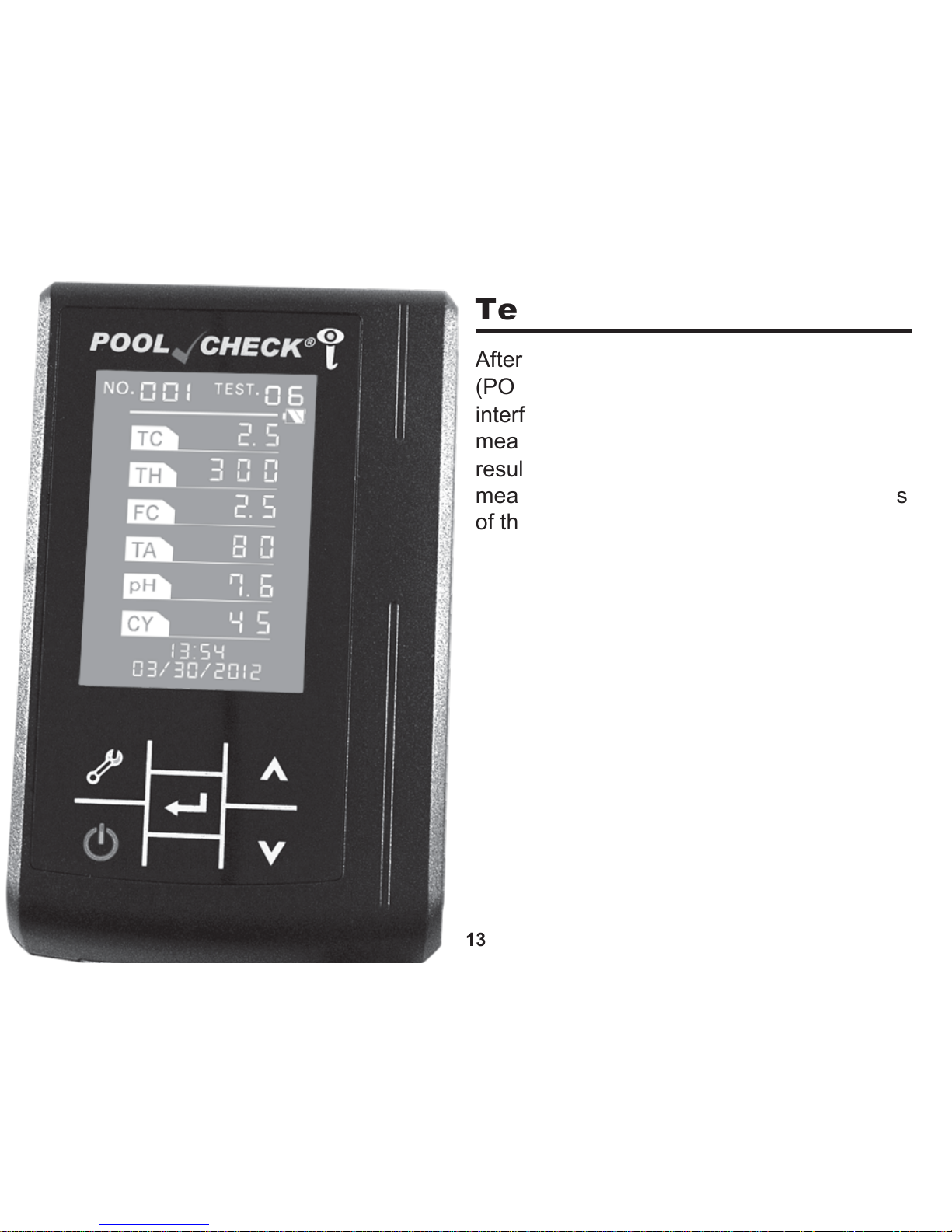
Test Procedure
After a successful Power On Self-Test
(POST), the screen will display the main
interface as shown on the left. “
NO.
001”
means that there are currently no stored
results in the instrument and the “
TEST.
06”
means that the instrument is set for analysis
of the Pool Check
®
i Pro 6 Test Strip.
13
Page 14
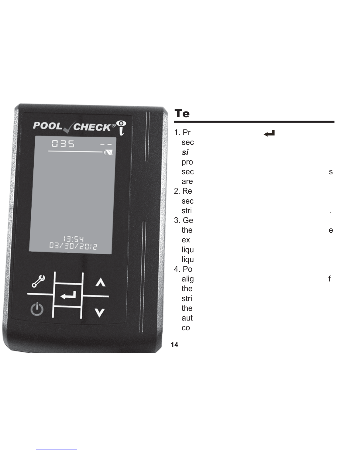
Test Procedure (Continued)
1. Press the Confirm key ( ) to start the 35
second countdown timer and
simultaneously dip the Test Strip into a
proper container of Pool or Spa water for 5
seconds without motion, being sure all pads
are immersed.
2. Remove Test Strip from the water after 5
seconds have passed. Immediately hold test
strip with one edge facing up. Do not shake.
3. Gently and briefly touch the long edge of
the strip to a flat, dry paper towel to remove
excess water. Only absorb the excess
liquid on the edge. No effort to absorb the
liquid on the back of the strip is required.*
4. Position the Test Strip in the Strip Slot and
align the end of the Test Strip to the end of
the Test Strip Slot. Be sure that the test
strip underside lays flat on the surface of
the Test Strip Slot. The instrument will
automatically SCAN the Test Strip after the
countdown timer reaches 0.
14
Page 15
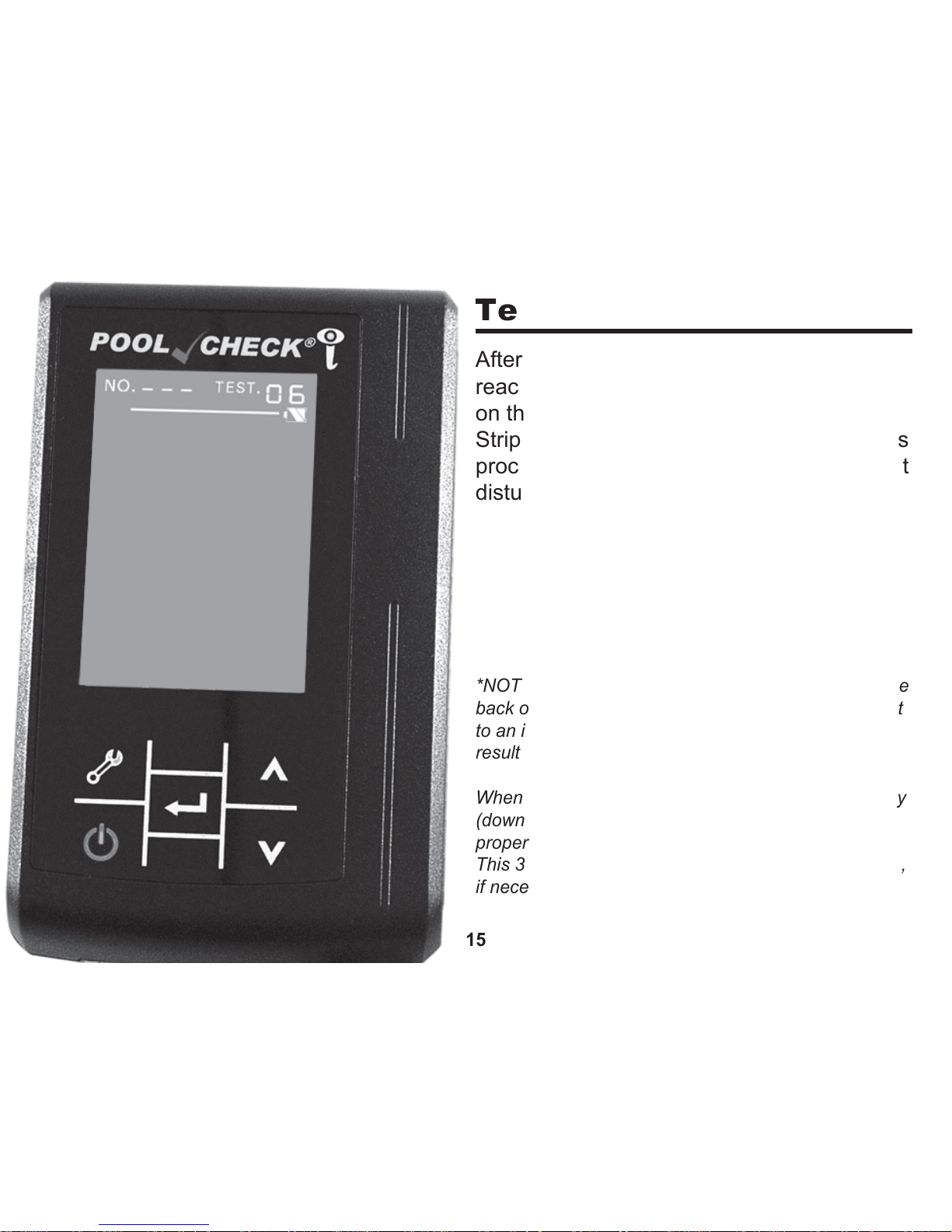
Test Procedure (Continued)
After the 35 second countdown timer
reaches 0, the display will appear as shown
on the left while the instrument retracts the
Strip Track and SCANS the Test Strip.* This
process will last for about 5 seconds. Do not
disturb the instrument during this process.
*NOTE: When both the Test Strip Slot surface and the
back of the Test Strip are dry, the Test Strip may shift
to an incorrect position during the SCAN, which will
result in improper analysis.
When reading the dry Control Strip tilt the meter away
(downward) 30° to keep the Control Strip positioned
properly in the Test Strip Slot during the full SCAN.
This 30° tilt can also be used for the Test Strip SCAN,
if necessary.
15
Page 16
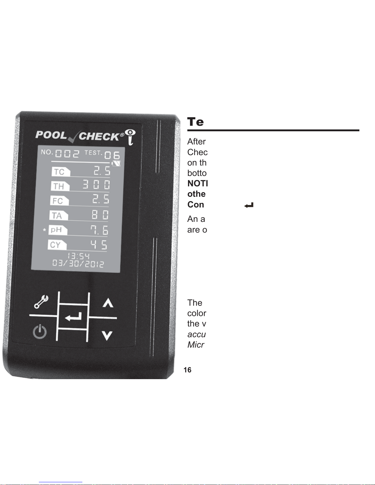
Test Procedure (Continued)
An asterisk (*) will be displayed if the values
are out of recommended ranges.
The pH pad should be compared to the pH
colors on the bottle label for verification of
the value. Service Operator: For best
accuracy, confirm pH results with an eXact
®
Micro 10 Photometer or pH meter.
After the SCAN of the Test Strip, the Pool
Check
®
i will display your results as shown
on the left. The current date is shown at the
bottom of the screen.
NOTICE: At this time you can access
other meter functions or press the
Confirm key ( ) and begin another test.
16
Menu Below or Above
TC 2.0 10.0
TH 150 400
FC 2.0 10.0
TA 80 120
pH all values are noted with *
CY 30 100
Page 17
Data Query
Press the Down key ( ) in the Main Interface to view the previous test result. Press
the Down key again to query the data previous to that, etc. Press the Up key ( ) to
scroll back up to more recent results.
NOTICE: Press the Main key ( ) in the Data Query Interface to return to the Main
Interface. Press the Confirm key ( ) to begin another test.
NOTICE: If an error code occurs, refer to the Error Codes Chart on page 23.
Print Test Results
Not available for this instrument.
Upload Operation
This instrument can upload test data to a computer running Windows XP, Windows Vista, and
Windows 7 Operating Systems to help with data management. For software download and
instructions visit
www.PoolCheckOnline.com
.
NOTE: The uploading feature requires the COM interface and we strongly recommend
you do not use a COM-to-USB switch cable.
Plug the 9-pin serial end of the cable into the computer then plug the Mini-USB end of the
cable into the Pool Check
®
i. Turn on the meter. Start the software and follow Software
Instructions to upload data from the meter.
NOTE: If you will be using the Data Management Software, DO NOT save more than 256
data points in the meter memory. Upload the data to the software, and then delete the
data from the meter before collecting the next 256 data points (see “Delete All Data”).
17
Page 18
Delete All Data
18
IMPORTANT: DO NOT PRESS THE
CONFIRM KEY ( ) UNLESS YOU WANT
TO DELETE ALL DATA
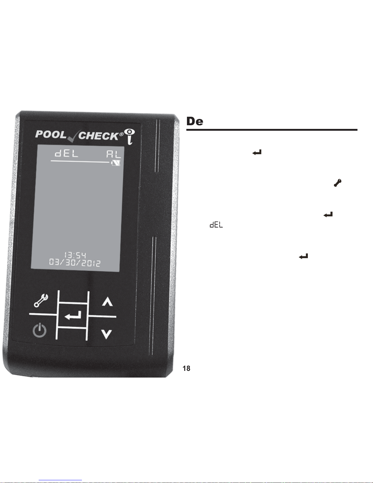
Press the Tool (Set-up) Function key ( )
once from the Main Interface. The display
will appear as shown to the left and
AL will
be blinking. Press the Confirm key ( ).
Both “
” and “AL” will begin blinking and
the unit will generate a “DING” sound to
notify you that the meter is ready to delete
data. Press the Confirm key ( ) again to
delete all data, or press any other key to
exit.
Page 19
Adjust SEN
(Sensitivity)
Settings
19
To calibrate the meter to a new lot of test strips,
use the SEN settings supplied on the bottle
label of the Pool Check
®
i Pro 6 Test Strips.
Follow the directions below to adjust the SEN
settings.
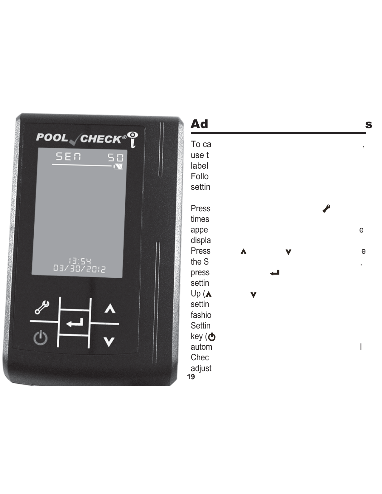
Press the Tool (Set-up) Function key ( ) two
times from the Main Interface. The display will
appear as shown to the left and the number on the
display will be blinking (the default setting is 50).
Press the Up ( ) or Down ( ) arrow key to change
the SEN setting for the first parameter (TC). Then,
press the Confirm key ( ) which stores the TC
setting and moves to the TH parameter. Press the
Up ( ) or Down ( ) arrow key to change the SEN
setting for the second parameter (TH). In similar
fashion, continue with adjustment of the SEN
Settings for FC, TA, pH, and CY. Press the Main
key ( ) to return to the Main Interface and
automatically store the SEN settings. If using Pool
Check
®
i Pro 3 Test Strips, you will only make SEN
adjustments to FC, TA, and pH.
Page 20
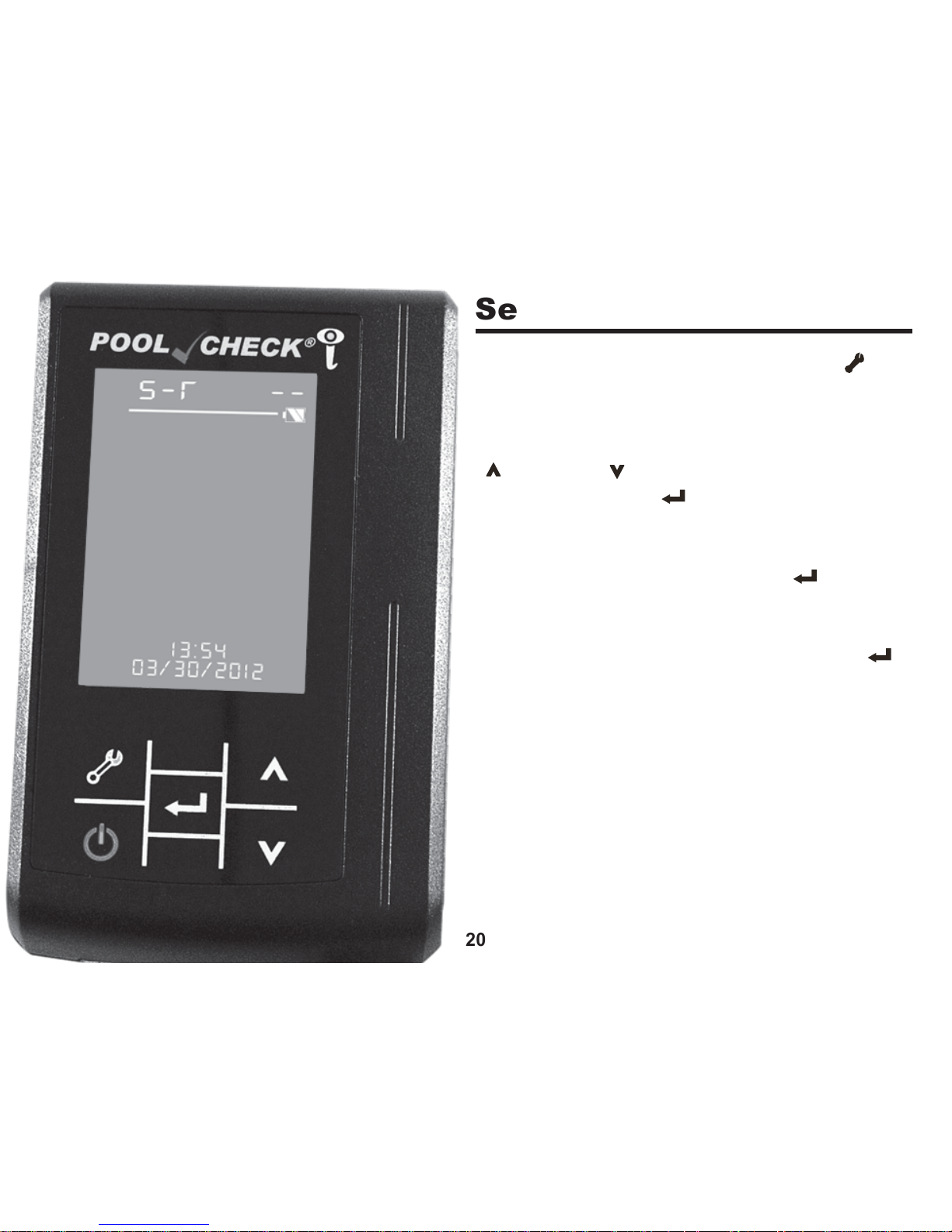
Set Time and Date
20
Press the Tool (Set-up) Function key ( )
three times from the Main Interface. The
display will appear as shown to the left and
the hour LED will be blinking. Press the Up
( ) or Down ( ) key to change the hour.
Press the Confirm ( ) key to set the hour.
The minutes LED will begin to blink. Adjust
the minutes in the same manner as with the
hour and press the Confirm key ( ) to begin
Date Configuration. Change the date Year,
Month, and Day in the same manner as used
above. You must press the Confirm key ( )
a final time to set the Time and Date.
Page 21
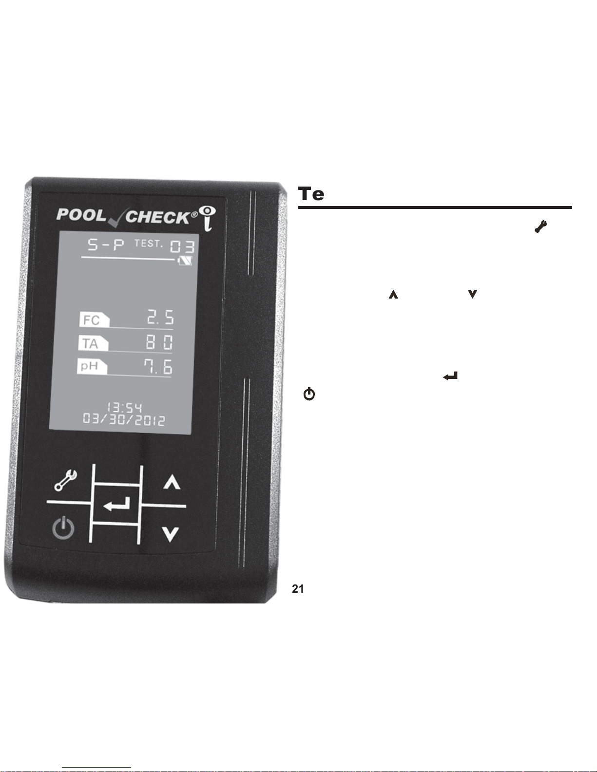
Test Type Configuration
21
Press the Tool (Set-up) Function key ( )
four times from the Main Interface. The
display will appear as shown to the left and
the current test configuration will be blinking.
Press the Up ( ) or Down ( ) key to adjust
the configuration. The display can be
configured to Pool Check
®
i Pro 3 or Pool
Check
®
i Pro 6 Test Strips. The
corresponding parameters will be displayed.
Press the Confirm key ( ) or the Main key
( ) to save the configuration chosen.
Page 22
22
Control Strip Procedure
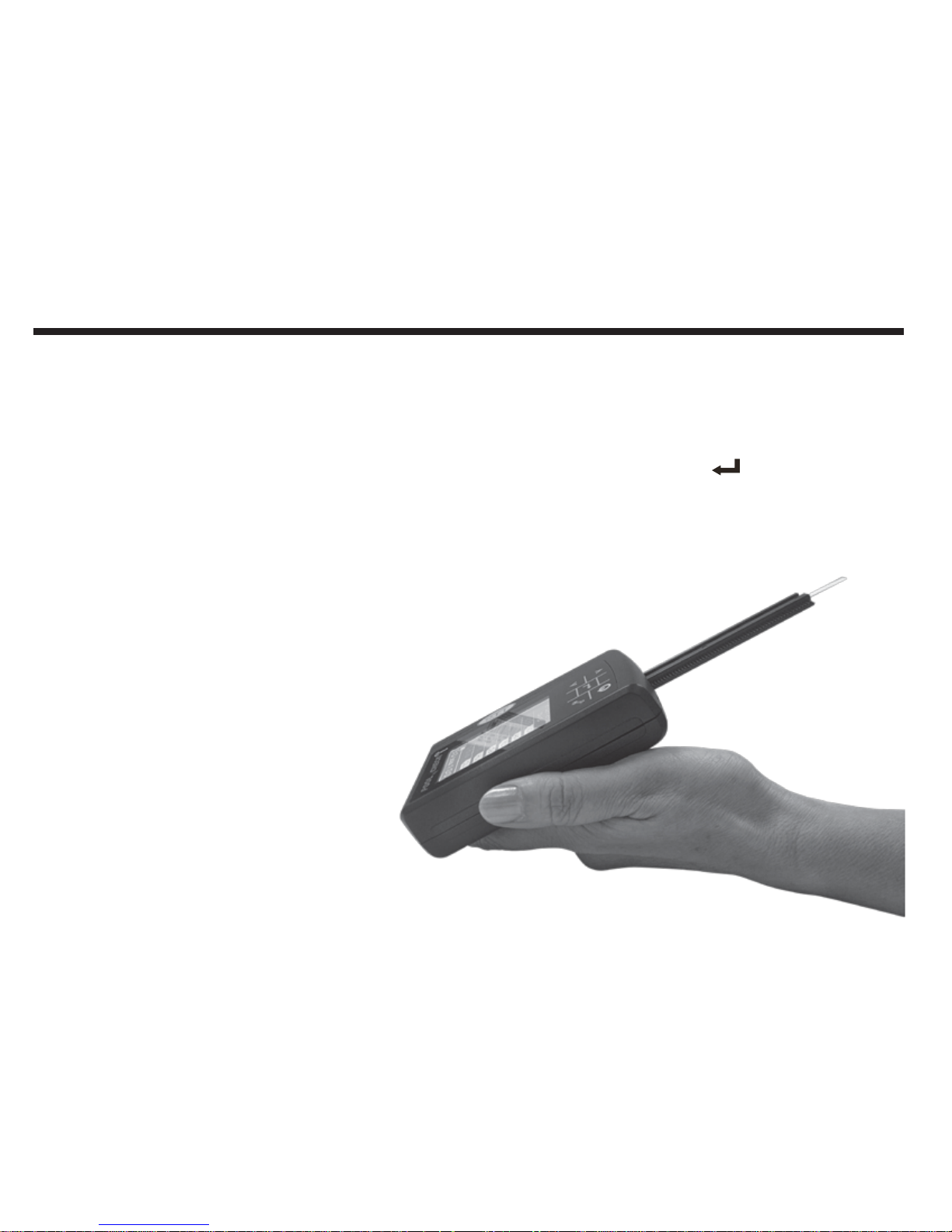
Use the supplied CONTROL STRIP to verify meter performance. IMPORTANT: Keep
the pre-printed CONTROL STRIP away from water. Match the meter SEN settings to
the SEN settings on the CONTROL STRIP container before scanning the strip (see
page 19). Place the CONTROL STRIP face up, lying flat and level, in the Test Strip
Slot. Tilt the meter downward at a 30° angle. Press the Confirm Key ( ) to start the 35
second countdown. Continue holding the meter downward at a 30° angle until the end
of the measurement. At the end of the countdown the Strip Track will retract and scan
the test strip. Compare the
displayed values with the value
ranges on the CONTROL STRIP
container label. Confirm that the
display values are in the ranges
listed on the container. If the
values are out of range,
reposition the end of the strip to
the end of the slot, being sure the
strip is flat and level in the slot.
Hold the meter at a 30° angle
(right) and repeat the scan.
NOTE: DO NOT SCRATCH OR
BEND THE CONTROL STRIP.
Page 23
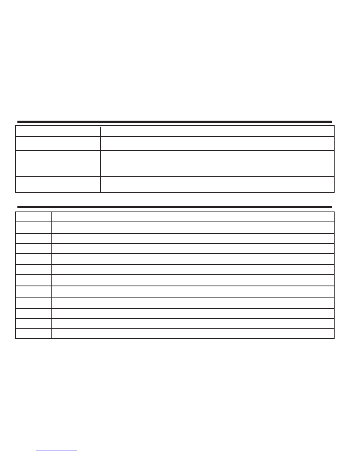
Troubleshooting
Failure Description
Fails to turn on
The result exceeds
inaccuracy specification
when compared to Micro 10
The Strip Track will not reset
Solution
Check the power source and recharge unit. If the unit is charged press reset on back of meter.
Clean the calibration pad and review your testing technique and procedure.
Pull
Strip Track
out of the meter, clean, and gently insert in the front of the unit.
Press ON to automatically reset the track
Error Codes
Error Code
06
07
08
09
10
11
12
13
14
24
28
Error Description
Key communication signal error
Transfer position sensor error, cannot detect the normal starting position (check if the motor is stuck)
EEPROM write error
EEPROM read error
Time initialization error
Memory blank
Not enough memory (when there are 900 results) remind user to delete data manually. Can still run test.
Failed to establish the upload
Upload request time out
No calibration pad, or the pad is too dark (white pad’s color is less than 400)
No memory, cannot store any data (remind user to delete the data manually)
23
Page 24

Reset Number
The test number (NO. on the display) will reset after reaching 999.
Tips for Best Results
24
1. Gently touch the long edge of the strip to a dry, flat paper towel to remove excess water. Do not wipe.
2. Do not touch reacted test pads to the paper towel when blotting the test strip.
3. Do not allow excess water to build up in the strip track. Excess water will allow the strip to shift in the
track.
4. Confirm the meter SEN settings to be sure they match the settings on the bottle label.
5. Protect the CONTROL STRIP and store it in the container provided. Handle it carefully to prevent
damage. Make sure your hands are clean and dry before handling the
CONTROL STRIP.
6. The CONTROL STRIP may bend under very dry or very humid conditions. If bending occurs, gently
flatten the strip before placing it in the Strip Track.
7. The meter will not upload more than 256 data points to the Data Management Software: DO NOT
save more than 256 data points in the meter memory if you plan to use the software. Upload the
data to the software, and then delete the data from the meter before collecting the next 256 data
points.
8. Best accuracy for pH and Cyanuric Acid is with Total Alkalinity at 100-120ppm. pH and CY values
will be over 50% low when TA is below 60ppm and over 50% high when TA is above 170ppm. If
your TA values are outside of 80-120ppm, use the eXact
®
Micro 10 or another method for reliable
measurement of pH and Cyanuric acid.
Page 25

Measurement Principle
The test strip pads develop different colors at different concentrations. The meter
measures light reflected by the colors and converts those measurements into
concentration values.
Instrument Cleaning
Please follow the procedure below:
1. Power on the unit and wait for it to finish the Power On Self-Test (POST).
2. The Test Strip Slot will automatically come out.
3. Remove track by holding the instrument securely and pulling the Strip Track straight out from the front.
4. Use tap water to wash the Strip Track and wipe with a clean, dry paper towel.
5. Hold the instrument securely and re-install the Strip Track.
NOTICE: You must only use mild cleaning solution and a damp cloth to wipe the surface of the instrument.
NOTICE: Do not store Pool Check®i near pool chemicals, acids, fertilizers, algaecides,
salt, oxidizing cleaning materials, corrosives, oxidizing or reducing chemicals which
may cause deterioration and damage by direct contact or chemical vapor contact.
25
Charging the Battery
Plug one end of the Mini-USB to USB cable into the Pool Check®i and the other into a
PC or the USB adapter provided.
NOTICE: DO NOT attempt to use any other USB adapter to charge the battery in the
Pool Check®i.
Page 26

Instrument Maintenance
1. Keep both the instrument and environment clean. Be careful not to drop the unit.
2. Rinse the Strip Slot regularly, depending upon usage.
Waste Disposal
You should obey the local disposal regulations. Used Test Strips can be discarded with
normal trash.
Packing, Storage, and Transportation
This instrument is sent in a sturdy carrying case and the foam inside the case improves
shock resistance. If the Pool Check
®
i has been stored for 3 months or more, then
recharge battery power for 4 hours to check if it is OK.
Storage and Transport Recommendation:
Temperature: -20°C – 55°C (-8°F – 131°F)
Humidity: Less than 80%
26
Page 27

27
Pool Check®i 1-Year Limited Warranty
Registration of your Pool Check®i Test Strip Analyzer must be received within 30 days
from date of purchase to activate the warranty. Every new Pool Check
®
i Test Strip
Analyzer is warranted to be free from defects in materials and workmanship for a period of
1 year from the date of purchase by the customer. ITS will repair or replace any part of the
product which, by our determination, is found to be faulty by reason of a manufacturing
defect. This non-transferable warranty does not cover equipment which has been
misused, tampered with, modified or damaged as a result of accident, water, grit, impact
or exposure to corrosive chemicals or oxidizers as described in the Pool Check
®
i owner’s
manual. If the meter is faulty or otherwise defective contact ITS by phone (+1-803-3299712 Ext. 226) or email ([email protected]) to describe the problem and obtain a return
authorization form before returning the photometer to ITS. Damage caused by improper
packing of the analyzer for return shipment to ITS will not be covered by the warranty.
Customers are responsible for shipping charges to ITS. ITS pays returned postage.
Registration is available over the phone (+1-803-329-9712 Ext. 0) or online at
www.PoolCheckOnline.com
(Personal data is kept confidential).
To protect your investment against damage caused by drops, spills, power surges and
other accidents, ITS recommends purchasing the Pool Check
®
i Assurance Program! For
only $160, this 3-year coverage entitles the owner to a 1-time replacement of the Pool
Check
®
i scanner for any reason. Simply return your inoperable Pool Check®i and ITS will
send you a brand new unit, no questions asked. Complete terms and conditions can be
found on our website at
www.PoolCheckOnline.com
.
Page 28
For US Inquiries and Re-Orders:
Industrial Test Systems, Inc.
1875 Langston Street,
Rock Hill, SC 29730 USA
Phone: 1-800-861-9712 - INSIDE THE U.S.
1-803-329-9712 - OUTSIDE THE U.S.
Fax: 1-803-329-9743
[email protected]
www.poolcheckonline.com
WWW.SENSAFE.COM
For European & Middle East Inquiries and Re-Orders:
ITS Europe, LTD
The UK Centre for Homeland Security
Building 7, Chilmark
Salisbury, Wiltshire SP3 5DU, United Kingdom
Tel: +44 (0)1722 717911
Fax: +44 (0) 1722 717941
[email protected]
www.poolcheckonline.com
WWW.ITSEUROPE.CO.UK
Contact Information
ITS Europe, Ltd.
Innovators of Water Quality Testing
28
 Loading...