

Page 1
e
OTh
B
O
O
e
m
e
1
p
B
h
u
n
N
7
yp
/
d
r
a
U
L
c
e
t
p
for
n
N
r
u
a
a
e
u
e
-866-7
www.
P
OOL B
Re
Y®III
l Insta
oolbo
attery
llation
Revise
8-POO
rodu
Power
Opera
01/2018
ts.com
d Sola
ion G
r Blank
ide
t
Pl
ase Read,
Follow, and
Save t
P
OL BOY®I
e POOL B
PB
P001R2
II is recom
Y®III syst
ended for
m should o
I
TROD
is Inst
se on rect
ly be used
CTIO
uction
ngular sha
the inte
1
Manu
ed pools w
ded applic
l.
ith or witho
tion.
t diving boards.
Page 2
GETTING STARTED
Required Tools
•
Drill/driver/screw gun with 5/16 hex driver bit
•
25 foot tape measure
•
Flat blade screwdriver
Select the Location
Select a location at one of the narrow ends of the pool. The location must:
•
Be away from the ladder
•
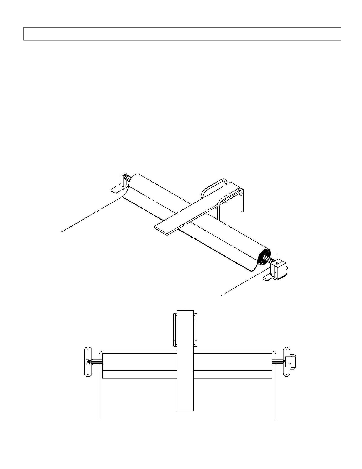
The suggested position of the motor side stand is the right side (see pictures below)
Suggested Layout
2
Page 3
Installation
1)
Position the Stands
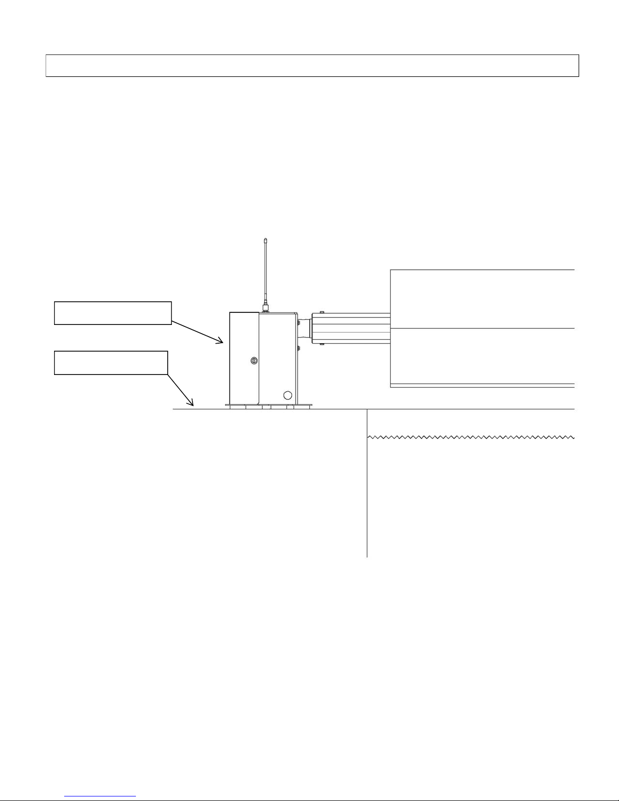
Position the stands in the selected location at one of the narrow ends of the pool. (Please see previous
page for suggested position.) The stands come fully assembled except for the installation of the
battery which is covered later in the instructions.
The Stand that will be referred to as the Drive side stand is the larger of the two. The Drive side stand
will house the motor and the battery and its control components.
POOL BOY® Stand
Pool Deck Level
3
Page 4
2)
Installing Cross Tubes
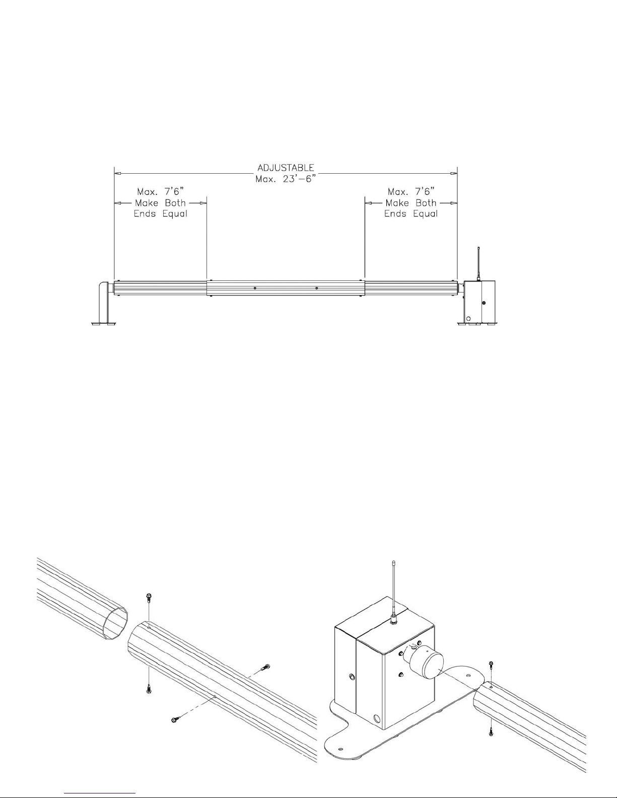
The tube assembly is adjustable to accommodate required widths from 17 to 23.5 feet. The
tube assembly has three tube sections. Two smaller tubes telescope from each end of the
larger diameter tube. See the drawings along with the below instructions. Do not exceed the
maximum lengths shown on the drawing. When installing and tightening screws care should
be taken to avoid stripping or breaking the screws. The use of a drill/driver with a slip clutch
is highly recommended.
Install the Cross Bolts
Slide a smaller diameter tube section into each end of the large tube. The ends of the
smaller tubes are predrilled for the hubs. The ends of the smaller tubes that are not drilled
are to slide into the larger center tube. It may be of some help that when sliding the tubes
together that the scribed lines on them match up.
Insert the drive and idler hubs into the ends of the tube assembly. Note that the hubs and the
tubes are pre drilled. Assemble so that the holes line up then insert and tighten the 4 screws
to join the outer tubes to the hubs of the stands.
Center the middle tube section between the two stands. Using 8 screws fasten the center
tube to the outer tubes through the predrilled holes in the outer tubes. Note the inner tubes
are not predrilled for the screws as these holes will be made by the self-drilling screws.
4
4
Page 5
3)
Battery Charging and Installation of Battery
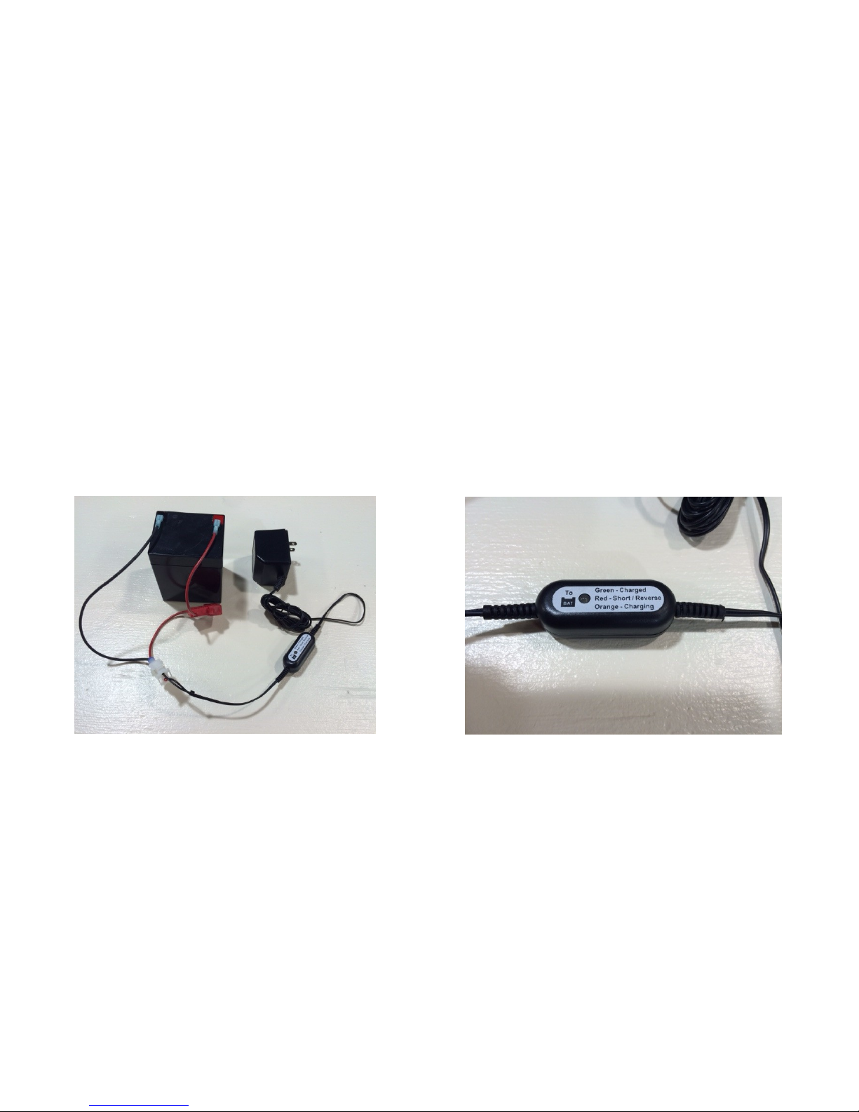
The battery is shipped uninstalled to the drive side stand. Prior to installing the battery and operating
the unit the battery needs to be charged.
Charging the battery
The battery needs to be charged prior to its first usage and occasionally based on the
number of times it is used. Also the battery needs to be charged prior to seasonal storage.
The battery must be removed from the drive side stand to charge it.
The battery is shipped with a connecting harness installed. To charge simply plug the mating
connectors of the charger and the battery together and then plug the charger into a 110 VAC outlet.
The charger is not to be used outdoors or in a wet or damp environment. The battery should be
charged in area with good ventilation. The battery and the charger must be kept away from external
heat sources and open flame or other ignition devices. The charger feed wiring is equipped with a
charge indicator light that will change color from orange to green when fully charged. Excessive
overcharging or undercharging may damage the battery and limit its life. See precautions printed on
the battery and separate sheet provided with charger for further information.
Battery properly attached to 110 VAC charger Charging Indicator
Note: The charge indicator light will be lit green if any one or more of the following
exists. The battery is fully charged, the fuse is blown or the wiring/connection
to the battery is not complete.
Seasonal storage: Prior to long periods of inactivity the battery should be removed from the
stand, charged and stored where it cannot freeze. It should be stored away
from excessive heat and flame.
Note: The battery and charger may vary from photos due to differing manufacturers.
5
Page 6
Installing the battery
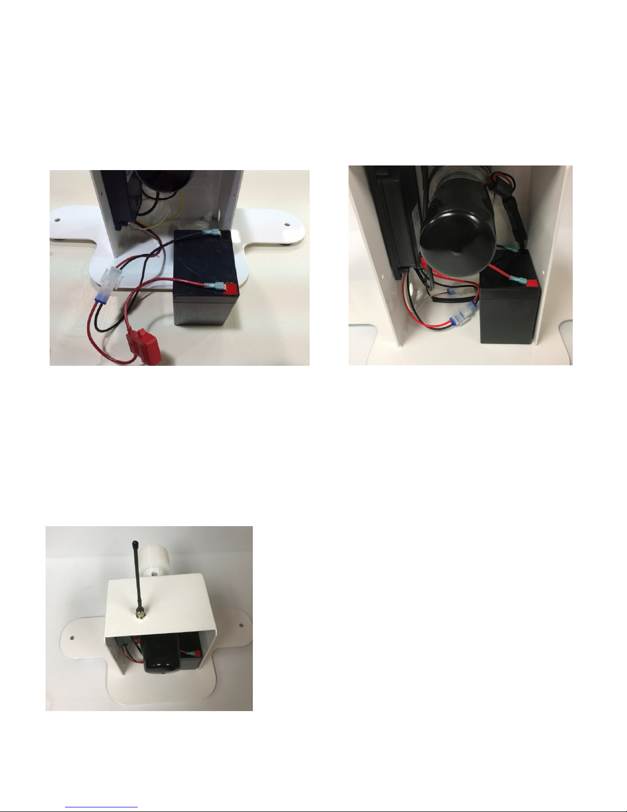
The battery is simply placed inside of the drive side stand on the right hand side (opposite side from
the controller). The connector from the battery is then plugged into the mating connector in the drive
side stand. When properly connected the wire colors will match. The below photos show a properly
connected and installed battery in the drive side stand. The wiring should be neatly tucked in next to
the battery and below the motor.
Proper battery connections Properly installed battery
Note: Battery may vary from photos due to differing battery manufacturers.
Antenna Installation
The wireless antenna is shipped uninstalled, it is simply screwed onto the connector at the top
of the drive side stand.
Photo of Drive side stand with Antenna Installed
6
Page 7
4) Test Run
With the cross tubes attached, test run the system. (See the OPERATION Section for instructions.) Ensure
the cross tube is securely attached to the Pool Boy® hubs and that it runs smoothly without wobble.
5) Install the drive stand cover
Install the cover using the supplied nylon screws.
6) Attach the solar blanket
Attach the solar blanket onto the cross tube in the manner prescribed by the blanket/blanket strap
manufacturer. Consult your solar blanket retailer for details. The blanket can wind onto the cross tube either
direction.
7) Install tether kit
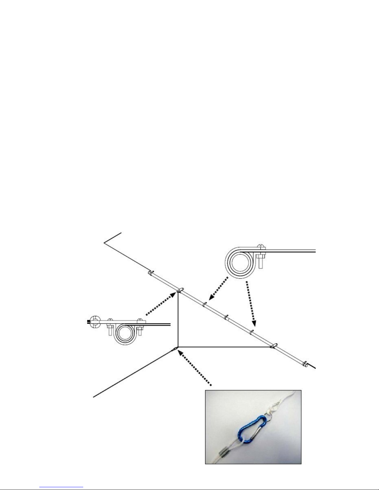
The tether kit attaches to the leading edge of the solar cover, opposite the end that wraps onto the cross
tube. The tether kit is used to guide the cover during extension and retraction.
1.
Carefully wrap the edge of the cover around the rods (2) 5ft pieces. Ensure the wrap is even and
square to the leading edge and center of the cover.
2.
Install the supplied (5) clips as shown in the following diagram. Bolt through the cover material, a hole
will need to be made thru the blanket. Install clamps evenly, approximately one every two feet.
3.
Snap the guide rope harness to the clamps as shown.
7
7
Page 8
Safety Items prior to operation
Visually inspect the pool prior to retracting or extending the solar blanket.
Ensure that the pool is clear of occupants and that no items will conflict with the solar blanket.
When not in use, store the remote control in a secure location in order to prevent unauthorized
operation.
Safety Features
The POOL BOY® powered solar blanket reel has operational safety features integrated into a
locking remote control that is designed to prevent unauthorized operation.
Remote Control:
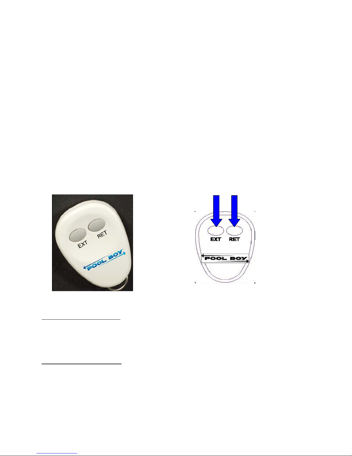
blanket. This remote control is activated for use only after both buttons (EXT / RET) are
depressed simultaneously and held for 2 seconds. Once activated, the remote control has a built
in 5 minute timer during which time, operation is possible. After five minutes elapses, the remote
will deactivate and operation will cease. To continue operation, the remote must be activated
again.
The key fob style remote control is used to extend and retract the solar
OPERATION
Activate the remote control by pressing simultaneously and holding both the EXT and RET buttons for 2
seconds. Note: Activating the remote starts a 5-minute timer for system operation.
Operate the System
To retract the solar blanket: press and release the RETRACT (RET) button on the remote control. To
stop retraction: press and release the RETRACT (RET) button again. Note: Retraction will also stop
automatically after 90 seconds.
It may be necessary to guide the blanket as it coils onto the reel. This can be done by grasping the
edge of the solar blanket or using the tether.
To extend the solar blanket: press and release the EXTEND (EXT) button on the remote control.
To stop extending the blanket: press and release the EXTEND (EXT) button again.
Note: Extension will also stop automatically after 90seconds.
It will be necessary to guide the blanket across the pool as it uncoils from the reel. This can be done
by grasping the edge of the solar blanket or using the tether.
*** If the desired installation configuration is different from the suggested installation on page 2, the
operating direction of the reel may be opposite of the buttons on the remote.
8
Page 9
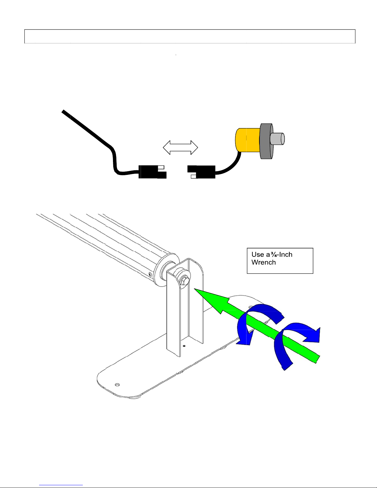
n
o
c
p
e
o
n
t
M
e
l
A
d
r
R
n
I
1)
Unplug the
2)
Use a ¾-in
the event
f a loss of
motor harn
h wrench
ower, a ma
ss.
socket to
ANU
ual overrid
urn the ree
L OVE
is provide
in the desi
RIDE
.
red directio
.
9
Page 10
Maintenance and Troubleshooting
Stands and tubes
The Pool Boy stands and tubes are designed to be weather resistant and Maintenance free. The
hubs are made of a special material that does not require lubrication. The stands are specially
multi coated to resist the elements and may be cleaned using a mild soap and water solution. The
use of a pressure washer is to be avoided due to the battery and other components inside of the
drive stand.
Battery
The battery located in the drive side stand must be charged occasionally for proper operation (see
battery charge instructions for this). The battery powered components located inside of the drive
side stand are weather resistant, they are not immersion proof. The battery and battery powered
components may be cleaned using a damp rag. Under no circumstances should the battery or
battery powered components be cleaned by using high pressure spray from a hose or pressure
washer.
Seasonal storage
Prior to long periods of inactivity the battery should be removed from the stand, charged and
stored where it cannot freeze. It should be stored away from excessive heat and flame. It should
then be charged again prior to usage. (see section on charging battery)
Remote (Fob)
The remote control (Fob) is weather resistant. It contains a button type battery (CR 2032). The
battery may require replacement at some time. This battery (CR 2032) is available at most retail
outlets that sell batteries. When replacing the battery be sure to install for correct polarity and
remove any protective sticker or film that may be on the battery.
No operation
If the system fails to operate first check and verify that you are doing the TWO button press
for TWO seconds
Then check the following items
Check/charge the main battery in the drive side stand
Check the fuse in the fuse holder at the battery connector. The fuse is an ATO 7.5 AMP.
Check/replace the battery in the remote (Fob)
Check the wiring inside of the drive side stand for corrosion and or loose wiring
After following the above checks if trouble persists call POOL BOY technical assistance at 866-
778-7665
prior to attempting operation. (See operation instructions for this)
10
Page 11

FCC Statement
© 2009 TouchTronics, Inc. All Rights Reserved. TouchTronics, the TouchTronics logo, and other TouchTronics marks are owned by
TouchTronics and may be registered. TouchTronics assumes no responsibility for any errors that may appear in this manual. Information
contained herein is subject to change without notice.
FCC Compliance and Advisory Statement.
following two conditions: 1) this device may not cause harmful interference, and 2) this device must accept any interference received,
including interference that may cause undesired operation. This equipment has been tested and found to comply with the limits for a Class
B digital device, pursuant to Part 15 of the FCC Rules. These limits are designed to provide reasonable protection against harmful
interference in a residential installation. This equipment generates, uses, and can radiate radio frequency energy and, if not installed or
used in accordance with the instructions, may cause harmful interference to radio communications. However, there is no guarantee that
interference will not occur in a particular installation. If this equipment does cause harmful interference to radio or television reception,
which can be determined by turning the equipment off and on, the user is encouraged to try to correct the interference by one or more of the
following measures: 1) reorient or relocate the receiving antenna; 2) increase the separation between the equipment and the receiver 3)
connect the equipment to an outlet on a circuit different from that to which the receiver is connected; 4) consult the dealer or an
experienced radio/TV technician for help. Any changes or modifications not expressly approved by the party responsible for compliance
could void the user’s authority to operate the equipment. Where shielded interface cables have been provided with the product or specified
additional components or accessories elsew here defined to be used with the installation of the product, they must be used in order to ensure
compliance with FCC regulations.
Canadian DOC Statement.
specified in the interference-causing equipment standard entitled “Digital Apparatus,” ICES-003 of the Department of Communications.
This digital device does not exceed the Class B limits for radio noise emissions from digital apparatus
This device complies with RSS-210 of Industry Canada. Operation is subject to the following two conditions: 1) this device may not
cause interference, and 2) this device must accept any interference, including interference that may cause undesired operation of the device.
© 2009 TouchTronics, Inc. Tous droits réservés. TouchTronics, le logo TouchTronics et les autres marques TouchTronics sont la
propriété exclusive de TouchTronics et sont susceptibles d’être des marques déposées. Toutes les autres marques sont la propriété
exclusive de leurs détenteurs respectifs. TouchTronics décline toute responsabilité en cas d’erreurs dans ce manuel. Les informations
énoncées dans le présent document peuvent faire l’objet de modifications sans avis préalable.
Déclaration FCC.
aux conditions suivantes: 1) l’équipement concerné ne doit pas causer d’interférences dangereuses, et 2) il doit accepter toute interférence
reçue, y compris les interférences risquant d’engendrer un fonctionnement indésirable. Cet équipement a été testé et déclaré conforme aux
limitations prévues dans le cadre de la catégorie B des appareils numériques défini par la section 15 du règlement de la FCC. Ces
limitations sont stipulées aux fins de garantir une protection raisonnable contre les interférences gênantes en installation résidentielle. Cet
équipement génère, utilise et diffuse des ondes radio, et s’il n’est pas installé ni utilisé en conformité avec les instructions dont il fait
l’objet, peut causer des interférences gênantes avec les communications radio. Cependant, nous ne pouvons vous garantir qu’une
interférence ne se produira pas dans une installation particulière. Si cet équipement produit des interférences graves lors de réceptions
radio ou télévisées qui peuvent être détectées en allumant et en éteignant l’équipement, vous êtes invités à les supprimer de plusieurs
manières: 1) Réorienter ou déplacer l’antenne de réception; 2) Augmenter la distance séparant l’équipement et le récepteur 3) Connecter
l’équipement à un circuit différent de celui auquel le récepteur est connecté; 4) Contacter votre revendeur ou un technicien radio/TV
qualifié. Toutes modifications ou tous changements effectués sans l’accord exprès de la partie responsable de la conformité aux normes
pourraient contraindre l’utilisateur à ne plus utiliser son équipement. Afin d’assurer la conformité avec les règlements FCC, les câbles
d’interface blindés fournis avec le produit doivent être utilisés, ainsi que tout autres composants ou accessoires également spécifiés, lors de
l’installation du produit.
Déclaration du Ministère des Communications Canadien.
d’interférences radio par des appareils numériques de catégorie B, telles que stipulées dans le cadre de la norme Appareils numériques
ICES-003 édictée par le Ministère canadien de l’industrie.
Cet équipement a été testé et déclaré conforme à la section 15 du règlement de la FCC. Son fonctionnement est soumis
Cet équipement a été déclaré conforme à la norme RSS-210 édictée par le Ministère canadien de l’industrie. Son fonctionnement est
soumis aux conditions suivantes: 1) l’équipement concerné ne doit pas causer d’interférences, et 2) il doit accepter toute interférence reçue,
y compris les interférences risquant d’engendrer un fonctionnement indésirable.
This hardware device complies with Part 15 of the FCC Rules. Operation is subject to the
Cet appareil numérique est conforme aux limitations concernant l’émission
11
Page 12
WARRANTY
DAYS CORPORATION
LIMITED WA RRANTY, REPLACEMENT PARTS & RETURNS POLICY
POOL BOY®
POOL BOY® LIMITED WARRANTY Effective January 1, 2016 Days Corporation (“Days”) warrants to the original purchaser
of POOL BOY® system components (the “Products”), for a period of three (3) years from the original sale date or date of dealer
installation, whichever is earlier (“Limited Warranty Period”), that the Products shall be free from defects in material and workmanship.
Days’ sole obligation under this warranty is, at its election, to repair, replace or make appr opriate adjustments concerning the Products
where Days’ inspection discloses any such defects in the Products occurring in normal usage within the limited warranty period. Days will,
at its option, repair or replace such part at no expense to you (provided, however, that you will be responsible for all shipping or
transportation costs in connection with transporting this unit to and from Days). Only warranty claims with prior authorization from Days
will be recognized; all other claims are invalid and will be denied. This warranty does not apply to abuse, misuse, neglect, negligence, error
of operations or to purposeful or accidental damage or damage due to “act of God” such as wind or rain da mage, flood, lightning or other
natural or similar occurrences. The POOL BOY® limited warranty coverage applies only to the Products and no other apparatus or
property to which the Products are affixed or attached. The POOL BOY® limited warranty is not transferable.
WARRANTY IS IN LIEU OF AND EXCLUDES ALL OTHER WARRANTIES NOT EXPRESSLY SET FORTH HEREIN
OPERATION OF LAW OR OTHERWISE
OF MERCHANTABILITY OR FITNESS FOR PURPOSE OR USE. Days is not responsible for removal or installation costs. UNDER NO
CIRCUMSTANCES SHALL DAYS’ LIABILITY FOR ANY DEF ECT IN THE PRODUCTS, WHETHER BASED ON CONTRACT, TORT, WARRANTY, STRICT
LIABILITY, OR ANY OTHER THEORY, EXCEED THE PURCHAS E PRICE OF THE DEFECTIVE P RODUCTS, AND DAYS SHALL HAVE NO LIABILI TY FOR
CONSEQUENTIAL, SPECIAL, INCIDENTAL, INDIRECT, EXEMPLARY OR PUNITIVE DAMAGES OF ANY KIND WHATSOEVER. This limited warranty
provides the limited purchaser of the Products with specific legal rights. The original purchaser of the Products may al so have other rights
that vary from state to state.
APPLICABILITY OF LIMITED WARRANTY TO REPLACEMENT PARTS. The terms and conditions of the POOL
BOY® Limited Warranty shall apply to any replacement parts provided to the original purchaser by Days in connection with any warranty
claim. Any replacement part is warranted for the balance of the Limited Warranty Period or ninety (90) days from the date of shipment of
the replacement part, whichever is longer. No markup will be paid by Days for warranty parts.
RETURNS POLICY. This returns policy applies to all Products returned to Days from the original purchaser during the Limited
Warranty Period. Prior authorization is required before any Product may be returned to Days. A Return Authorization Number is required
for Days’ acceptance of returned Products. Warranty claims submitted without proof of the original purchase date are not covered by this
Warranty and will be denied. Parts credit (if applicable) will be sent after Days tests the Product and validates the warranty claim.
, AND DAYS EXPRESSLY EXCLUDES ANY IMPLIED WARRANTIES, INCLUDING ANY IMPLIED WARRANTY
, WHETHER EXPRESS OR IMPLIED BY
THE FOREGOING
PBBP001R2
Please direct all questions concerning the POOL BOY® Limited Warranty to:
Days Corporation
Warranty Claims
P.O. Box 668
Elkhart, IN 46515
Telephone: 1-866- 778-7665
Facsimile: 1-574- 266-6083
12
 Loading...