

Pony Italy LAV Installation, Use And Maintenance Manual
LAV
Lav
(Istr. LAV/4 - Ed. 2013)
INSTALLAZIONE USO E MANUTENZIONE
INSTALLATION USE AND MAINTENANCE
INSTALLATION USAGE ET ENTRETIEN
INSTALLATION WARTUNG UND BEDIENUNGSANLEITUNG
INSTALACION FUNCIONAMIENTO Y MANTENIMIENTO

EGREGIO CLIENTE,
Ci complimentiamo con Voi per aver preferito una ns. macchina. Siamo certi che questo impianto Vi darà piena
soddisfazione e corrisponderà a lungo alle Vs. esigenze.
Vi trasmettiamo questo opuscolo che riteniamo indispensabile per ottenere sempre il massimo rendimento dal Vs.
impianto.
La direzione, unitamente ai propri collaboratori ed agenti, sarà ben lieta di ricevere eventuali Vs. suggerimenti per
migliorare sempre la sua produzione.
Lieta di poterVi annoverare tra la ns. affezionata Clientela, porgiamo distinti saluti.
La Direzione
DEAR CUSTOMER,
We are grateful you chose our machine and are confident the preference you have shown will ensure your complete
satisfaction.
We have pleasure in enclosing a copy of the instruction manual for your machine. By carefully following the
instructions in the manual you will be able to obtain trouble free operation from your plant, and find valuable
information and suggestions for future requirements.
We welcome any suggestions that may assist us to improve the performance and design of our range of machinery and
we look forward to hearing from you in the future.
It is our sincere wish that you will always remain our satisfied customer. Yours faithfully,
The Management
CHER CLIENT,
Vous avez choisi, de préférence, notre machine. Avec vous, nous nous réjouissons de votre choix judicieux et sommes
sûrs que la machine vous donnera entière et pleine satisfaction.
Consultez le livre d’instructions pour tirer le maximum de votre nouvel outil, Vous y trouverez également des conseils
et des suggestions qui vous seront utiles à l’avenir.
La Direction, les collaborateurs et agents invitent toute suggestions susceptible d’améliorer notre production. D’avance,
nous vous en remercions.
En nous félicitant de compter parmi nos nombreux clients, nous restons à votre service et Vous présentons, cher Client,
nos salutations distinguées.
La Direction
LIEBER KUNDE,
Herzlichen Glückwunsch zu dem Kauf Ihrer neuen Bügelmaschine.
Diese Maschine wurde nach den neusten technischen Erkenntnissen konstruiert und gefertigt.
In Ihrem Interesse bitten wir Sie, vor Inbetriebnahme und Arbeitsbeginn die Bedienungsanleitung Ihres Gerätes
sorgfältig zu lesen, um unnötige Beanstandungen zu vermeiden.
Unsere Mitarbeiter haben alles daran gesetzt, Ihnen hervorragende Qualität zu bieten. Sollten Sie dennoch Fragen zur
Bedienung oder Technik haben stehen wir Ihnen immer gerne zur Verfügung.
Wir danken Ihnen für Ihr Vertrauen und wünschen Ihnen viel Erfolg mit diesem Neuerwerb.
Mit freundlichen Grüßen
Die Direktion
MUY SENOR NUESTRO,
Le damos las gracias por haber elegido nuestra maquina. Estamos seguros que responderà a sus necesidades y le darà
completa satisfacción.
Adjuntamos el manual de funcionamiento y mantenimiento indispensable para garantizar un optimo rendimiento de la
maquina y donde Ud. podrà encontrar todos los consejos necesarios para su bueno mantenimiento futuro.
Tanto la Dirección como los Agentes de venta y Distribuidores le agradeceriamos cualquier consejo para mejorar
nuestra producción.
Contentos de contar Ud, entre nuestros Clientes, aprovechamos la ocasion para saludarle atentamente.
La Dirección

i:\gestione istruzione\_presse\pressa lavanderia\aggiornamenti\_3lav it.doc (febbraio 00)
INDICE
IT
CAPITOLO 1.......................................…........1-1
AVVERTIMENTI PER LA SICUREZZA
DELLE PERSONE E DELLE COSE...…......1-1
CAPITOLO 2..................................................2-1
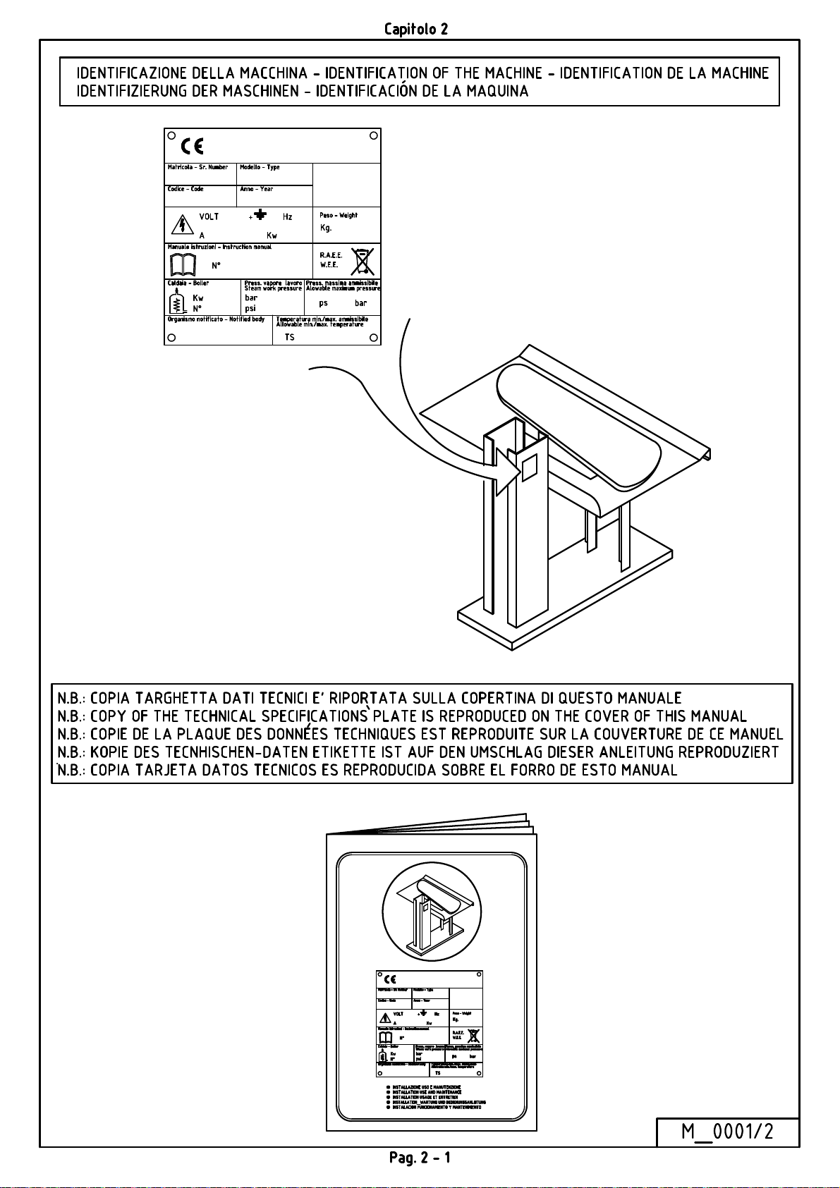
IDENTIFICAZIONE DELLA MACCHINA..2-1
CAPITOLO 3..............................................CVCBN3-1
INSTALLAZIONE ............................................. 3-1
IMBALLO ................................................................ 3-1
TRASPORTO ........................................................... 3-1
DISIMBALLAGGIO E POSA DELLA MACCHINA3-1
COLLEGAMENTO ACQUA (PER MACCHINE
CON CALDAIA) ...................................................... 3-1
COLLEGAMENTO ARIA COMPRESSA ............... 3-2
ALLACCIAMENTO VAPORE E RITORNO
CONDENSA (PER MACCHINE SENZA CALDAIA)3-2
COLLEGAMENTO ELETTRICO (PER MACCHINE
CON CALDAIA) ...................................................... 3-2
COLLEGAMENTO ELETTRICO (PER MACCHINE
SENZA CALDAIA E SENZA COMPRESSORE) ... 3-3
PERICOLI, AVVIAMENTO, MANUTENZIONE
ELETTROPOMPE ................................................... 3-3
LAVAGGIO CALDAIA (PER MACCHINE CON
CALDAIA) ............................................................... 3-3
GUASTI ................................................................ 3-7
GUASTI SUBITO DOPO L’INSTALLAZIONE PER
MACCHINE CON CALDAIA ................................. 3-7
GUASTI SUBITO DOPO L’INSTALLAZIONE PER
MACCHINE SENZA CALDAIA ............................ 3-7
GUASTI SUBITO DOPO L’INSTALLAZIONE PER
MACCHINE CON O SENZA CALDAIA ............... 3-7
GUASTI ALLA CALDAIA ED AL CONTROLLO
LIVELLO ELETTRONICO ..................................... 3-7
GUASTI ALL’IMPIANTO PNEUMATICO PER
PRESSE CON DISCESA A DUE PULSANTI (VEDI
SCHEMA PN_00200) .............................................. 3-9
GUASTI ALL’IMPIANTO PNEUMATICO PER
PRESSE CON DISCESA A PEDALE CON
TELAINO (VEDI SCHEMA PN_00202) .............. 3-10
BRUCIATURA DELLA RESISTENZA CALDAIA3-11
GUASTI AL COMPRESSORE INCORPORATO . 3-11
MODALITÀ RICHIESTA PEZZI DI
RICAMBIO ........................................................ 3-12
ACCANTONAMENTO O DEMOLIZIONE .. 3-12
CAPITOLO 10..............................................10-1
DATI TECNICI, QUOTE DI INGOMBRO,
ALLACCIAMENTI.......................................10-1
CAPITOLO 11..............................................11-1
USO DELLA PRESSA ....................................... 3-3
VERIFICHE PRELIMINARI ................................... 3-3
DISCESA PIANO SUPERIORE .............................. 3-4
APERTURA DEI PIANI (RISALITA PIANO
SUPERIORE) ........................................................... 3-4
REGOLAZIONE DELLA PRESSATA (PER TUTTE
LE VERSIONI)......................................................... 3-4
FUNZIONAMENTO DEL CONTROLLO LIVELLO
ELETTRONICO DELLA CALDAIA ...................... 3-4
FUNZIONAMENTO DEL TERMOSTATO DI
SICUREZZA (SOLO PER CALDAIA 20LT) .......... 3-5
OPERAZIONI DA COMPIERE AL TERMINE
DEL LAVORO .................................................... 3-5
MANUTENZIONE ............................................. 3-5
MANUTENZIONE SETTIMANALE ...................... 3-5
MANUTENZIONE SEMESTRALE/ANNUALE .... 3-6
SCHEMI ELETTRICI..................................11-1
CAPITOLO 12..............................................12-1
SCHEMI PNEUMATICI...............................12-1
CAPITOLO 13..............................................13-1
DISEGNI PEZZI DI RICAMBIO.................13-1
CAPITOLO 14..............................................14-1
DISTINTE CODICI......................................14-1

i:\gestione istruzione\_presse\pressa lavanderia\aggiornamenti\_4lav gb.doc (febbraio 00)
INDEX
EN
CHAPTER 1..................................................1-1
SAFETY PRECAUTIONS..............................1-1
CHAPTER 2..................................................2-1
MACHINE IDENTIFICATION.....................2-1
CAPITOLO 4.........................................DFDGDHH4-1
INSTALLATION ................................................ 4-1
PACKING ................................................................. 4-1
TRANSPORT ........................................................... 4-1
UNPACKING AND LAYING OF THE MACHINE 4-1
WATER CONNECTION (FOR MACHINE WITH
BOILER) .................................................................. 4-1
COMPRESSED AIR CONNECTION ...................... 4-2
STEAM AND CONDENSATION RETURN
CONNECTION (FOR MACHINES WITHOUT
BOILER) .................................................................. 4-2
ELECTRICAL CONNECTION (FOR MACHINES
WITH BOILER) ....................................................... 4-2
ELECTRICAL CONNECTION (FOR MACHINES
WITHOUT BOILER OR COMPRESSOR) .............. 4-3
DANGER, STARTING, MAINTENANCE FOR
ELECTROPUMP ...................................................... 4-3
BOILER WASHING (FOR MACHINE WITH
BOILER) .................................................................. 4-3
USE OF THE PRESS ......................................... 4-3
PRELIMINARY CONTROLS ................................. 4-3
LOWERING THE UPPER BUCK ........................... 4-4
OPENING THE BUCK (RAISING THE UPPER
BUCK) ...................................................................... 4-4
ADJUSTMENT OF CLOSING PRESSURE (FOR
ALL MODELS) ........................................................ 4-4
OPERATION OF THE ELECTRONIC LEVEL
CONTROL ............................................................... 4-4
OPERATION OF THE SAFETY THERMOSTAT
(ONLY FOR BOILER 20LT) ................................... 4-4
BREAKDOWNS ................................................. 4-6
IMMEDIATELY FOLLOWING INSTALLATION
FOR MACHINES WITH BOILER ........................... 4-6
IMMEDIATELY FOLLOWING INSTALLATION
FOR MACHINES WITHOUT BOILER ................... 4-8
IMMEDIATELY FOLLOWING INSTALLATION
FOR MACHINES WITH AND WITHOUT BOILER4-8
BREAKDOWNS ON THE BOILER AND ON THE
ELECTRONIC LEVEL CONTROL ......................... 4-8
BREAKDOWNS ON THE PNEUMATIC CIRCUIT
FOR PRESSES WITH TWO-BUTTONS
LOWERING (SEE DRAWING PN_00200) ........... 4-10
BREAKDOWNS ON THE PNEUMATIC CIRCUIT
FOR PRESSES WITH PEDAL LOWERING (SEE
DRAWING PN_00202) .......................................... 4-11
BREAKDOWNS ON THE BOILER ...................... 4-12
BOILER HEATING ELEMENT BURNT OUT ..... 4-13
BREAKDOWNS ON THE BUILT-IN
COMPRESSOR ...................................................... 4-13
ORDERING SPARE PARTS ........................... 4-14
STORAGE OR DEMOLITION ...................... 4-14
CHAPTER 10..............................................10-1
TECHNICAL SPECIFICATIONS,
ENCUMBRANCE, CONNECTIONS...........10-1
CHAPTER 11-..............................................11-1
ELECTRICAL DIAGRAMS........................11-1
CHAPTER 12...............................................12-1
PNEUMATIC DIAGRAMS..........................12-1
SHUTTING DOWN OF THE MACHINE ....... 4-4
MAINTENANCE ................................................ 4-5
WEEKLY MAINTENANCE ................................... 4-5
SIX MONTHLY / YEARLY MAINTENANCE ...... 4-6
CHAPTER 13...............................................13-1
DRAWING OF SPARE PARTS...................13-1
CHAPTER 14...............................................14-1
CODE’S LIST......................................…......14-1

I:\gestione istruzione\_Presse\PRESSA LAVANDERIA\AGGIORNAMENTI\_5LAV Fr .doc
TABLE DES
MATIERES
FR
CHAPITRE 1.................................................1-1
CONSEILS POUR LA SECURITE DES
PERSONNES ET DES CHOSES..…….........1-1
CHAPITRE 2..................................................2-1
IDENTIFICATION DE LA MACHINE…....2-1
CAPITOLO 5...........................................................5-1
INSTALLATION ................................................ 5-1
EMBALLAGE .......................................................... 5-1
TRANSPORT ........................................................... 5-1
DEBALLAGE ET MISE EN PLACE DE LA
MACHINE ................................................................ 5-1
BRANCHEMENT EAU (POUR MACHINES AVEC
CHAUDIERE) .......................................................... 5-1
BRANCHEMENT AIR COMPRIME ...................... 5-2
BRANCHEMENT VAPEUR ET RETOUR
CONDENSAT (POUR MACHINES SANS
CHAUDIERE) .......................................................... 5-2
BRANCHEMENT ELECTRIQUE (POUR
MACHINES AVEC CHAUDIERE) ......................... 5-2
BRANCHEMENT ELECTRIQUE (POUR
MACHINES SANS CHAUDIERE ET SANS
COMPRESSEUR) .................................................... 5-3
DANGER, MISE EN MARCHE, ENTRETIEN POUR
L’ELECTROPOMPE ............................................... 5-3
LAVAGE CHAUDIERE (POUR MACHINES AVEC
CHAUDIERE) .......................................................... 5-3
USAGE DE LA PRESSE.................................... 5-3
VERIFICATIONS PRELIMINAIRES ..................... 5-3
DESCENTE PLATEAU SUPERIEUR .................... 5-4
OUVERTURE DES PLATEAUX (REMONTE
PLATEAU SUPERIEUR) ........................................ 5-4
REGLAGE DU PRESSAGE (POUR TOUTES LES
VERSIONS) ............................................................. 5-4
FONCTIONNEMENT DU CONTROLE NIVEAU
ELECTRONIQUE DE LA CHAUDIERE ................ 5-4
FONCTIONNEMENT DU THERMOSTAT DE
SECURITE (SEULEMENT POUR CHAUDIERE
20LT) ........................................................................ 5-5
OPERATIONS A EFFECTUER A LA FIN DU
TRAVAIL ............................................................ 5-5
PANNES ............................................................... 5-7
PANNES IMMEDIATEMENT APRES
L’INSTALLATION, POUR MACHINES AVEC
CHAUDIERE ............................................................ 5-7
PANNES IMMEDIATEMENT APRES
L’INSTALLATION, POUR MACHINES SANS
CHAUDIERE ............................................................ 5-7
PANNES IMMEDIATEMENT APRES
L’INSTALLATION, POUR MACHINES AVEC OU
SANS CHAUDIERE ................................................. 5-8
PANNES A LA CHAUDIERE ET AU CONTROLE
NIVEAU ELECTRONIQUE .................................... 5-8
PANNES AU SYSTEME PNEUMATIQUE, POUR
PRESSES AVEC DESCENTE A DEUX POUSSOIRS
(VOIR SCHEMA PN_00200) ................................. 5-10
PANNES AU SYSTEME PNEUMATIQUE POUR
PRESSES, AVEC DESCENTE A PEDALE AVEC
CHASSIS (VOIR SCHEMA PN_00202) ................ 5-11
PANNES A LA CHAUDIERE ............................... 5-12
BRULURE DE LA RESISTANCE CHAUDIERE . 5-13
PANNES AU COMPRESSEUR INCORPORE ...... 5-13
MODALITES COMMANDE PIECES DE
RECHANGE ...................................................... 5-14
STOCKAGE OU DEMOLITION ................... 5-15
CHAPITRE 10.............................................10-1
DONNEES TECHNIQUES, COTES D’
ENCOMBREMENT, BRANCHEMENTS..10-1
CHAPITRE 11..............................................11-1
SCHEMAS ELECTRIQUES.......................11-1
CHAPITRE 12..............................................12-1
SCHEMAS PNEUMATIQUES....................12-1
CHAPITRE 13..............................................13-1
DESSINS PIECES DE RECHANGE............13-1
ENTRETIEN ....................................................... 5-5
ENTRETIEN PAR SEMAINE ................................. 5-6
ENTRETIEN SEMESTRIEL/ANNUEL .................. 5-6
CHAPITRE 14..............................................14-1
LISTES DES CODES...................................14-1

i:\gestione istruzione\_presse\pressa lavanderia\aggiornamenti\_6lav ted.doc (febbraio 00)
INHALT
DE
KAPITEL 1.....................................................1-1
SICHERHEITSHINWEISE FÜR PERSONEN
UND GEGENSTÄNDE..................................1-1
KAPITEL 2....................................................2-1
IDENTIFIZIERUNG DER MASCHINE.......2-1
CAPITOLO 6 ...................................................... 6-1
INSTALLATION ................................................ 6-1
VERPACKUNG ....................................................... 6-1
TRANSPORT ........................................................... 6-1
AUSPACKEN UND AUFSTELLEN DER
MASCHINE ............................................................. 6-1
WASSERANSCHLUSS (FÜR MASCHINEN MIT
KESSEL) .................................................................. 6-1
DRUCKLUFTANSCHLUS ...................................... 6-2
DAMPFANSCHLUSS UND KONDENSRÜCKLAUF
(FÜR MASCHINEN OHNE KESSEL) .................... 6-2
ELEKTRISCHER ANSCHLUSS (MASCHINEN MIT
KESSEL) .................................................................. 6-3
ELEKTRISCHER ANSCHLUSS (MASCHINEN
OHNE KESSEL UND OHNE KOMPRESSOR) ...... 6-3
GEFAHREN, INBETRIEBNAHME, WARTUNG
DER ELEKTROPUMPE .......................................... 6-3
REINIGUNG DES KESSELS (FÜR MASCHINEN
MIT KESSEL) .......................................................... 6-3
STÖRUNGEN ..................................................... 6-7
STÖRUNGEN SOFORT NACH DER
INSTALLATION BEI MASCHINEN MIT KESSEL6-7
STÖRUNGEN SOFORT NACH DER
INSTALLATION BEI MASCHINEN OHNE
KESSEL .................................................................... 6-8
STÖRUNGEN AM KESSEL SOFORT NACH DER
INSTALLATION BEI MASCHINEN MIT UND
OHNE KESSEL ........................................................ 6-8
STÖRUNGEN AM KESSEL UND AN DER
ELEKTRONISCHEN NIVEAUKONTROLLE ........ 6-8
STÖRUNGEN AN DER PNEUMATISCHEN
ANLAGE DER PRESSEN MIT SENKUNG MIT
ZWEI DRUCKKNÖPFEN (SIEHE PLAN PN 00200)6-11
STÖRUNGEN AN DER PNEUMATISCHEN
ANLAGE MIT PEDALSENKUNG UND
SICHERHEITSRAHMEN (SIEHE PLAN PN 00202)6-12
STÖRUNGEN AM KESSEL .................................. 6-14
DURCHGEBRANNTE KESSELWIDERSTÄNDE6-15
STÖRUNGEN AM EINGEBAUTEN
KOMPRESSOR ...................................................... 6-15
BESTELLUNG DER ERSATZTEILE ........... 6-15
BEISEITELEGUNG ODER
VERSCHROTTUNG ........................................ 6-16
KAPITEL 10.................................................10-1
GEBRAUCH DER PRESSE .............................. 6-4
EINLEITENDE KONTROLLEN ............................. 6-4
SENKEN DER OBEREN BÜGELFLÄCHE ........... 6-4
ÖFFNUNG DER PLATTEN (AUFSTIEG DER
OBEREN ARBEITSPLATTE) ................................. 6-4
EINSTELLUNG DER PRESSTÄRKE (FÜR ALLE
AUSFÜHRUNGEN) ................................................. 6-5
BETRIEB DER ELEKTRONISCHEN
NIVEAUKONTROLLE DES KESSELS ................. 6-5
FUNKTION DES SICHERHEITSTHERMOSTATES
(NUR FÜR 20LT KESSEL) ..................................... 6-5
DURCHZUFÜHRENDE ARBEITE NACH
BEENDIGUNG DES GEBRAUCHS ................ 6-5
WARTUNG ......................................................... 6-5
WÖCHENTLICHE WARTUNG .............................. 6-6
HALBJÄHRLICHE/JÄHRLICHE WARTUNG ...... 6-7
TECHNISCHE DATEN, RAUMBEDARF,
ANSCHLÜSSE..............................................10-1
KAPITEL 11................................................11-1
ELEKTRISCHE SCHALTPLÄNE..............11-1
KAPITEL 12.................................................12-1
PNEUMATISCHE SCHALTPLÄNE................12-1
KAPITEL 13.................................................13-1
TEILSCHNTTZEICHNUNGEN ................13-1
KAPITEL 14.................................................14-1
VERZEICHNIS DER CODES ....................14-1

i:\gestione istruzione\_presse\pressa lavanderia\aggiornamenti\_7lav spa.doc (febbraio 00)
ÍNDICE
ES
CAPÍTULO 1...................................................1-1
ADVERTENCIAS PARA LA SEGURIDAD DE
LAS PERSONAS Y DE LAS COSAS..............1-1
CAPÍTULO 2...................................................2-1
IDENTIFICACIÓN DE LA MÁQUINA…....2-1
CAPITOLO 7 ...................................................... 7-1
INSTALACIÓN .................................................. 7-1
EMBALAJE ............................................................. 7-1
TRANSPORTE ......................................................... 7-1
DESEMBALAJE Y UBICACIÓN DE LA MÁQUINA7-1
CONEXIÓN DEL AGUA (PARA MÁQUINAS CON
CALDERA) .............................................................. 7-1
CONEXIÓN DEL AIRE COMPRIMIDO (PARA
MÁQUINAS SIN COMPRESOR) ........................... 7-2
CONEXIÓN DEL VAPOR Y RETORNO DE
CONDENSADOS (PARA MÁQUINAS SIN
CALDERA) .............................................................. 7-2
CONEXIÓN ELÉCTRICA (PARA MÁQUINAS CON
CALDERA) .............................................................. 7-2
CONEXIÓN ELÉCTRICA (PARA MÁQUINAS SIN
CALDERA Y SIN COMPRESOR) .......................... 7-3
PELIGRO DE DESCARGAS ELÉCTRICAS,
PUESTA EN MARCHA, MANTENIMIENTO
ELECTROBOMBA .................................................. 7-3
LAVADO DE LA CALDERA (PARA MÁQUINAS
CON CALDERA) ..................................................... 7-3
EMPLEO DE LA PRENSA ............................... 7-3
VERIFICACIONES PRELIMINARES .................... 7-3
BAJADA DEL PLATO SUPERIOR ........................ 7-4
APERTURA DE LOS PLATOS (SUBIDA PLATO
SUPERIOR) .............................................................. 7-4
REGULACIÓN DEL PRENSADO (PARA TODAS
LAS VERSIONES) ................................................... 7-4
FUNCIONAMIENTO DEL CONTROL DEL NIVEL
ELECTRÓNICO DE LA CALDERA ...................... 7-4
FUNCIONAMIENTO DEL TERMOSTATO DE
SEGURIDAD (SÓLO PARA CALDERA 20LT) .... 7-5
OPERACIONES A REALIZAR AL FINAL DEL
TRABAJO ........................................................... 7-5
AVERÍAS ............................................................. 7-7
AVERÍAS INMEDIATAMENTE DESPUÉS DE LA
INSTALACIÓN PARA MÁQUINAS CON
CALDERA ............................................................... 7-7
AVERÍAS INMEDIATAMENTE DESPUÉS DE LA
INSTALACIÓN PARA MÁQUINAS SIN CALDERA7-7
AVERÍAS INMEDIATAMENTE DESPÚES DE LA
INSTALACIÓN PARA MÁQUINA CON O SIN
CALDERA ............................................................... 7-8
AVERÍAS EN LA CALDERA Y EN EL CONTROL
ELECTRÓNICO DE NIVEL ................................... 7-8
AVERÍAS A LA INSTALACIÓN NEUMÁTICA
PARA LAS PRENSA CON BAJADA CON DOS
PULSADORES (VER EL ESQUEMA PN_00200) 7-10
AVERÍAS EN LA INSTALACIÓN NEUMÁTICA
PARA PRENSAS CON BAJADA A PEDAL CON
BASTIDOR PROTECTOR (VER ESQUEMA
PN_00202) .............................................................. 7-11
AVERÍAS EN LA CALDERA ............................... 7-12
QUEMADURA DE LA RESISTENCIA DE LA
CALDERA ............................................................. 7-13
AVERÍAS EN EL COMPRESOR INCORPORADO7-13
MODALIDAD PARA EL PEDIDO DE
REPUESTOS ..................................................... 7-14
ALMACENAJE O DEMOLICIÓN ................. 7-15
CAPÍTULO 10..............................................10-1
DATOS TÉCNICOS, DIMENSIONES,
CONEXIONES………………………………10-1
CAPÍTULO 11...............................................11-1
ESQUEMAS ELÉCTRICOS ……….………11-1
CAPÍTULO 12...............................................12-1
ESQUEMAS NEUMÁTICOS……………….12-1
MANTENIMIENTO .......................................... 7-5
MANTENIMIENTO SEMANAL ............................ 7-6
MANTENIMIENTO SEMESTRAL/ANUAL .......... 7-6
CAPÍTULO 13...............................................13-1
DIBUJOS DE LOS REPUESTOS..................13-1
CAPÍTULO 14...............................................14-1
LISTAS DE LOS CÓDIGOS.........................14-1

CAPITOLO 1 – CHAPTER 1 - CHAPITRE 1 – KAPITEL 1 – CAPÍTULO 1
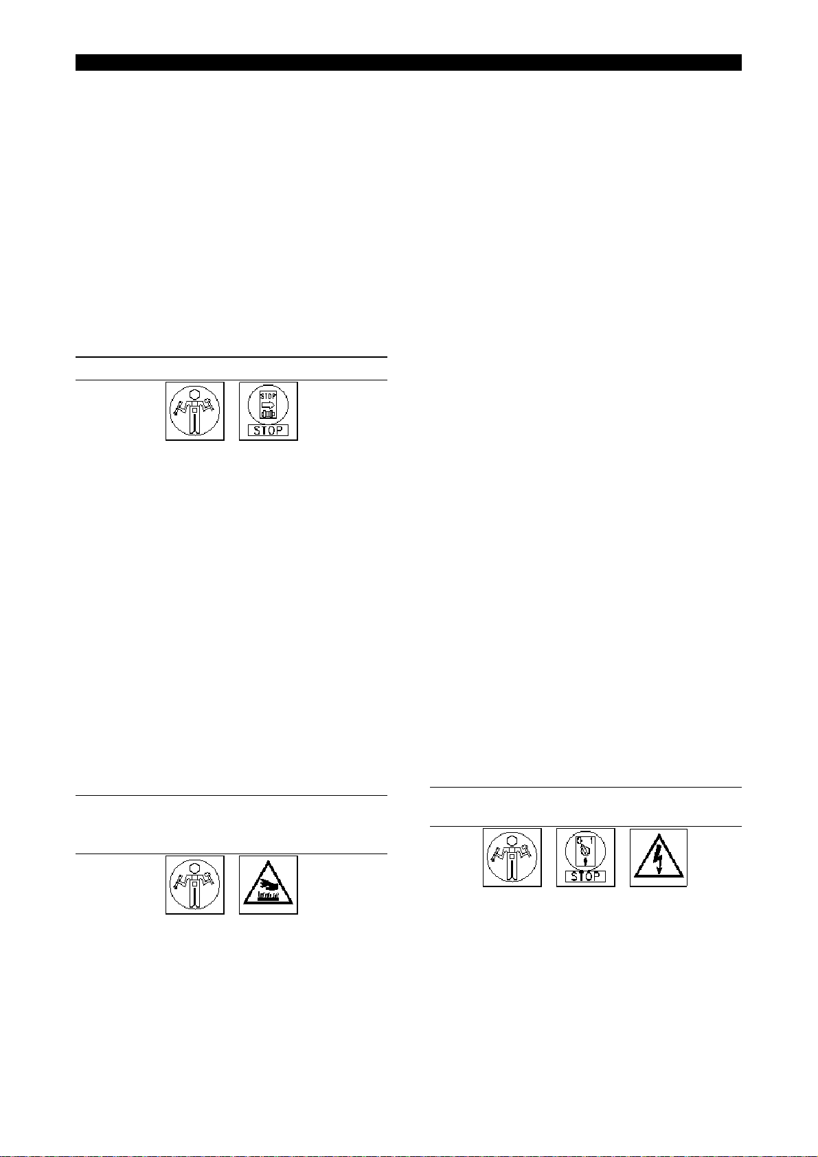
SEGNALI DI PRESCRIZIONE, PERICOLO E INDICAZIONE
PRESCRIPTION, DANGER AND INDICATION SIGNALS
SIGNAUX DE PRESCRIPTION, DANGER ET INDICATION
VERBOTS-, GEBOTS- UND WARNZEICHEN
SEÑALES DE PRESCRIPCIÓN, PELIGRO Y INDICACIÓN
Divieto di togliere i carter di protezione con impianto funzionante
Do not remove protection covers when machine is working.
Défense d’enlever les couvercles de protection pendant le fonctionnement de la machine.
Abnahme der Schutzgehäuse bei anlaufender Anlage verboten
Prohibido quitar la tapa de protección durante el funcionamiento de la maquina.
Divieto di eseguire interventi di manutenzione a macchina in moto
Do not effect maintenance when machine is working.
Défense d’exécuter toutes entretiens pendant le fonctionnement de la machine.
Wartungseinsätze bei anlaufender Anlage verboten
Prohibido efectuar todos mantenimientos durante el funcionamiento de la maquina.
Vietata l’apertura del quadro elettrico al personale non autorizzato.
Authorized personnel only can open the electric panel.
Défense d’ouvrir le cadre électrique par le personnel non autorisé.
Öffnung des Gehäuses für Unbefugte verboten.
Prohibido abrir el tablero eléctrico para obreros no autorizados
Vietato utilizzare acqua per spegnere l’incendio.
Do not extinguish with water
Défense d’eteindre avec de l’eau.
Mit Wasser löschen verboten
Obbligo di riposizionare i carter di protezione prima di azionare l’impianto
Prohibido apagar con agua
Protection covers must be put on before using the machine.
Il est obligatoire de remettre le couvercle de protection avant d’actionner la machine.
Vor Inbetriebsetzung der Anlage Schutzgehäuse wiedereinbauen
Está obligatorio reponer las tapas de protección antes que se ponga en marcha la maquina.
Consultare il manuale d’uso, lo schema elettrico e le procedure.
Consult the instruction’s manual, the electric diagram and procedures.
Consulter le manuel d’emploi.
Betriebsanweisung, Schaltschema und Vorgänge lesen
Consultar el manual d’empleo.
Attenzione pericolo di scottature alle mani
High temperatures! Possibility of burning!
Hautes températures! Danger de brûlures!
Warnung vor Handverbrennungen
Temperaturas elevadas! Peligro de quemaduras!
Quadro in tensione
Danger: electricity
Danger électrique
Warnung vor gefährlicher elektrischer Spannung 380 V
Peligro: Tensión eléctrica
Pag. 1-1
CAPITOLO 1 – CHAPTER 1 - CHAPITRE 1 – KAPITEL 1 – CAPÍTULO 1
INFORMAZIONI PER LO SMALTIMENTO
DELL’APPARECCHIATURA
L’etichetta con il contenitore di
spazzatura mobile barrato presente
sul prodotto, indica che il prodotto non
deve essere smaltito tramite la
convenzionale procedura di
smaltimento dei rifiuti domestici.
Per evitare eventuali danni per l’ambiente e per la
salute umana, il prodotto deve essere separato dagli
altri rifiuti domestici e consegnato al punto di raccolta
designato per il riciclo dei rifiuti elettrici o elettronici.
La raccolta differenziata ed il riciclo degli apparecchi di
scarto servirà a conservare le risorse naturali ed a
salvaguardare l’ambiente e la salute delle persone. Lo
smaltimento abusivo del prodotto sarà perseguito a
norma di legge.
Per maggiori dettagli sui centri di raccolta disponibili
contattare l’ente locale competente o il rivenditore del
prodotto.
INFORMATION FOR THE DISPOSAL OF THE
EQUIPMENT
The label showing the crossed mobile
garbage container on the product,
points out that the product must not be
disposed through the conventional
procedure of disposal of the domestic
waste.
To avoid possible damage to the environment and for
improved human health, the product has to be
separated from the other domestic waste and delivered
to the designated collection point for the recycling of
electric or electronic waste.
The diversified collection and the recycling of rejected
instruments will serve to preserve the natural resources
and to safeguard the environment and the health of the
people. The unauthorized disposal of the product will be
prohibited according to the local laws.
For greater details on the available collection centres
please contact the competent local authority or the
retailer of the product.
RENSEIGNEMENTS POUR L’ECOULEMENT DE LA
MACHINE
L’Etiquette avec la poubelle barrée
qu’il y a sur le produit, signifie que le
produit même ne peut pas être écoulé
par le canal conventionnel
d’écoulement des ordures
domestiques.
Pour éviter d’éventuels dommages pour l’habitat et le
salut de l’homme, la machine doit être séparée des
autres ordures domestiques et livrée jusqu’au point de
recueil désigné pour le recyclage des rebuts électriques
et électroniques.
Le recueil diversifié et le recyclage des pièces de rebut
servent pour la conservation des résources naturelles
et à préserver l’habitat et le salut des gens.
L’écoulement abusif du produit sera poursuivi aux
termes de la loi.
Pour tout autre renseignement concernent les points de
recueils disponibles, s’adresser à l’organisme
compétent local ou au revendeur du produit,
INFORMATION ÜBER ENTSORGUNG VON
ALTGERÄTEN
Das auf dem Produkt befindliche
Etikett, das eine durchgestrichene
Abfalltonne auf Rädern darstellt,
weist auf das Verbot hin, dieses
Produkt als Hausabfall zu entsorgen.
Um eventuelle Umwelt– und
Gesundheitsschäden zu vermeiden, muß das Produkt
von anderen Hausabfällen getrennt werden und zur
Entsorgung an zuständige Recyclingfirmen bzw.
Sammelorte für Elektro- und Elektronik-Altgeräte
übergeben werden.
Die getrennte Sammlung und Recycling der Altgeräte
dient zur Bewahrung des natürlichen Reichtums und
zum Schutz von Umwelt und Gesundheit.
Eine nicht umweltgerechte Beseitigung des Produkts
wird gesetzlich bestraft.
Für weitere Information betreffend der verfügbaren
Sammelorte, wenden sich an die örtliche zuständigen
Behörden oder an Ihren Produkthändler.
INFORMACIONES POR LA LIQUIDACIÓN DE LA
INSTRUMENTACIÓN
La etiqueta con el contenedor de
basura móvil barrato presente sobre
el producto, indica que el producto no
tiene que ser eliminado por el
convencional procedimiento de
liquidación de los rechazos
domésticos.
Para evitar eventuales daños por el entorno y por la
salud humana, el producto tiene que ser separado por
los demás rechazos domésticos y remitidos al punto de
colección designado por el reciclo rechazos eléctricos o
electrónicos.
La colección distinta y el reciclo aparatos de descarte
servirá a conservar los recursos naturales y a
salvaguardar el entorno y la salud de las personas. La
liquidación abusiva del producto será perseguida a
norma de ley.
Para mayores detalles sobre los centros de colección
disponible contactar al ente local competente o el
detallista del producto.
Pag. 1-2

ITALIANO CAPITOLO 3 ITALIANO
Capitolo 3 cvcbn
INSTALLAZIONE
IMBALLO
La macchina può essere imballata in tre modi:
1) CON FONDALE IN LEGNO E MACCHINA
AVVOLTA IN CELLOPHANE: formato da un
fondale (che ne permette il sollevamento e lo
spostamento con mezzi meccanici (paranchi,
muletti). La macchina, imbullonata sul fondale
nei piedini d’ancoraggio, è avvolta con un
sacco di polietilene (PE) fissato con graffette
sul fondale.
2) CON INDUPACK: con l’aggiunta di un
involucro in cartone bloccato con regge
metalliche su pallet.
3) SOLO INCARTATURA
TRASPORTO
o animali.
e) Togliere i bulloni che fissano i piedini della
macchina sul fondale.
f) Imbragare la macchina con due funi
(verificare che siano idonee al peso totale
della macchina rilevabile dal cartellino dati
tecnici), l'una nella parte posteriore, l'altra
nella parte anteriore della macchina; quindi,
con l'ausilio di un muletto o paranco
meccanico, sollevare la macchina e
posizionarla nel luogo destinato
all'installazione senza più muoverla con
braccia umane.
g) Montare l’eventuale supporto porta-ferro:
inserire il braccio poggia-ferro nel supporto e,
successivamente, riposizionare il bullone.
h) Montare l’eventuale braccio a molla e fissarlo
con l’apposito bullone
i) Collegare gli eventuali tubi di rame del gruppo
ferro vapor.
j) Collegare il tubo di rame alimentazione
Subito al ricevimento della macchina imballata,
notificare per scritto al trasportatore eventuali
danni subiti dall’imballo durante il trasporto. Infatti,
qualora tali danni abbiano interessato anche la
macchina, l’assicuratore del corriere risponderà
solo se questi danni presunti sono stati subito
segnalati
Tutte le operazioni di installazione devono essere
eseguite da personale qualificato, munito delle
necessarie protezioni (guanti, protezioni
antinfortunistiche etc.).
Non usare getti di acqua contro la macchina per
nessun motivo ed evitare bruschi movimenti o urti
violenti.
vapore ai raccordi.
k) Collegare il tubo di rame ritorno condensa ai
raccordi.
l) Al termine dell'installazione rimontare con
cura i pannelli e le protezioni della macchina
assieme agli accessori in dotazione.
Devono essere osservate alcune misure di
distanza dalle pareti e dalle altre macchine, al fine
di garantire una lavorazione più scorrevole ed una
perfetta manutenzione.
La macchina non necessita d’alcun ancoraggio al
pavimento. Si raccomanda di sistemarla
perfettamente in piano.
COLLEGAMENTO ACQUA
(PER MACCHINE CON CALDAIA)
La macchina non deve essere trasportata da
braccia umane, bensì con l'ausilio di muletti o
paranchi meccanici.
Trasportare la macchina completa di imballo nel
luogo più prossimo al punto di installazione e
procedere al suo disimballaggio.
DISIMBALLAGGIO E POSA DELLA
MACCHINA
(VEDI A PAG. 10-5)
Predisporre un tubo in ferro zincato da 3/8”GAS
fino a cm 100 dalla macchina. Alla sua estremità
montare un rubinetto a sfera con portagomma e,
mediante un tubo di gomma resistente alla
pressione dell’acquedotto, collegare il
portagomma d’entrata acqua “POS. 23” al
rubinetto. Qualora la caldaia della macchina
Procedere nel seguente modo:
a) Togliere, se esistente, l’indupack munendosi
d’appositi attrezzi meccanici.
b) Togliere la copertura in polietilene (PE) che
avvolge la macchina.
c) Verificare che la macchina non abbia subito
danneggiamenti durante il trasporto.
d) Asportare dal fondale tutti gli accessori che
non sono fissati o imbullonati sul bancale
perché, spostando la macchina dal bancale,
possono cadere danneggiando cose, persone
Pag. 3-1
debba essere alimentata da un serbatoio,
chiedere informazioni alla Ditta produttrice sulle
modifiche da eseguire sulla pompa.
Collegare il rubinetto di scarico “POS. 6” con la
fognatura mediante un tubo rigido termoisolato.
Qualora non fosse disponibile nelle vicinanze un
pozzetto della fognatura, oppure se fosse vietato
scaricarvi acqua calda, utilizzare una tanica da
20-30 litri per raccogliere lo scarico caldaia (che
scaricherete quando si sarà raffreddato).
Utilizzare un tubo rigido isolato di ferro o rame, al
fine di evitare ustioni.
ITALIANO CAPITOLO 3 ITALIANO
N.B.: qualora le normative del Vostro Paese lo
richiedano, al fine di evitare contaminazioni dell’
acquedotto, è necessario installare un serbatoio
d’alimentazione acqua oppure un apparecchio
che eviti il riflusso d’acqua eventualmente
inquinata (ad esempio GIACOMINI R 624).
N.B.: È consigliabile evitare il collegamento
all’addolcitore dell’acqua. Infatti, l’eventuale uso
d’acqua depurata in piccole caldaie elettriche
provoca
la formazione d’abbondante schiuma, che
viene risucchiata quando viene usato il vapore,
con conseguente danneggiamento degli abiti.
Qualora si riscontrasse un’eccessiva durezza
dell’acqua, è possibile installare un addolcitore
che riduca i sali disciolti nell’acqua a non meno di
10 francesi (7 inglesi).
COLLEGAMENTO ARIA COMPRESSA
b) Venga usato del tubo in ferro o rame del
diametro minimo consigliato (1/2” GAS).
c) I tubi siano a pendenza costante, i raggi delle
curve siano di almeno 50 mm. ( 2 inches),
non esistano strozzature nella tubazione e la
lunghezza di ciascun tubo non superi i 2,5
metri (98,5 inches).
Tutte queste precauzioni sono indispensabili per
evitare risucchi d’acqua e, qualora non fossero
realizzabili, è necessario effettuare un
collegamento tradizionale, cioè con scaricatore di
condensa a caldaia centrale, come illustrato nel
disegno. Per quest’ultimo tipo di collegamento,
derivare dalla parte alta della conduttura centrale
di vapore un tubo di ferro da 1/2" GAS e farlo
arrivare a 100 cm dalla macchina.
All’estremità di questo tubo montare un rubinetto a
sfera, onde poter escludere la macchina
dall’impianto.
Il collegamento del rubinetto a sfera al raccordo
(VEDI A PAG. 10-5)
La macchina deve essere alimentata con aria
compressa pulita, senza condense né oli, ed
avente una pressione di 8-10 bar (116-145 psi).
Predisporre un tubo in ferro zincato o rilsan da
3/8” GAS fino ad 1 metro dalla macchina.
Alla sua estremità montare un rubinetto a sfera a
3 vie. Questo rubinetto a 3 vie permette di
alimentare la macchina (posizione 1=ON=OK)
oppure di disattivarla (posizione 0=OFF=STOP),
scaricando l’aria rimasta nella macchina
attraverso il silenziatore. In questo modo, qualora
fosse necessario eseguire una qualsiasi
manutenzione alla macchina, si ha la garanzia,
ruotando il rubinetto in posizione 0=OFF=STOP
(oppure facendo scivolare la ghiera), che non
esista più alcun pericolo di natura pneumatica
(getti d’aria, movimenti di pistoni, etc.).
Mediante
un tubo in rilsan interno=12mm (0,47
inches) resistente ad almeno 20 bar (290 psi) di
pressione, collegare il rubinetto alla macchina.
ALLACCIAMENTO VAPORE E
RITORNO CONDENSA
entrata vapore si può fare con un tubo di rame
avente un diametro interno di 14 mm.
Vi ricordiamo che la macchina funziona con
vapore alla pressione di 4-6 bar (58-87 psi)
perciò, se la macchina viene allacciata ad un
generatore di vapore funzionante ad una
pressione più elevata, è necessario installare un
riduttore di pressione.
Collegare al raccordo ritorno condensa uno
scaricatore di condensa da 1/2" GAS a secchiello
rovesciato con filtro (SPIRAX SARCO HM 007
oppure JUCKER SA8).
A valle dello scaricatore si deve montare una
valvola di ritegno a clappè onde evitare
contropressioni allo scaricatore.
E’ indispensabile montare un rubinetto a sfera
sulla tubazione di ritorno condensa (tubo da 1/2"
GAS) onde permettere l’esclusione della
macchina dall’impianto. Volendo, è possibile
applicare un rubinetto “POS. 10” di by-pass dello
scaricatore, al fine di riscaldare la pressa più
velocemente quando si accende per cominciare la
stiratura (vedi paragrafo “Uso della pressa”).
COLLEGAMENTO ELETTRICO (PER
MACCHINE CON CALDAIA)
(PER MACCHINE SENZA CALDAIA)
(VEDI A PAG. 10-4)
Come illustrato nel disegno, è possibile collegare
la macchina ad una piccola caldaia in modo
diretto, cioè senza scaricatore.
E’ però indispensabile che:
a) La quota “H” dal pavimento del foro di scarico
condensa della macchina superi di almeno
200 mm (8 inches) il livello acqua “K” in
caldaia, misurato dallo stesso piano.
Pag. 3-2
(VEDI A PAG. 10-6 e schema relativo alla
propria versione)
Accertarsi che la tensione e frequenza di linea
corrispondano a quelle segnate sulla targa dati
tecnici della macchina (vedere pag. 2-1).
Predisporre una linea elettrica trifase con neutro e
terra, inserire il cavo nel passacavo “POS. 8”,
bloccarlo con il collare “POS. 9” ed effettuare il
collegamento ai morsetti d’entrata corrente.
La linea di corrente dovrà essere dotata di un
interruttore automatico magnetotermico
ITALIANO CAPITOLO 3 ITALIANO
differenziale da 30 mA, con presa e spina ad
interblocco meccanico.
Il dimensionamento della linea e dell’interruttore
dovrà essere fatto come da tabella.
Si fa obbligo, pena la decadenza della garanzia, di
collegare la macchina ad una buona messa a
terra secondo le normative vigenti.
Controllare, prima del collaudo iniziale, che i
morsetti di tutti i componenti elettrici non si siano
allentati durante il trasporto.
Dopo il collegamento, verificare il senso di
rotazione dei motori (compressore, pompa,
aspiratore) e, qualora fosse errato, invertire tra
loro due delle tre fasi in ingresso.
Rimontare tutte le pannellature e le protezioni
della macchina.
COLLEGAMENTO ELETTRICO (PER
MACCHINE SENZA CALDAIA E SENZA
COMPRESSORE)
Controllare che l’albero giri a mano.
Per questo scopo utilizzare l’intaglio per cacciavite
sull’estremità dell’albero lato ventilazione.
Quando la pompa rimane inattiva deve essere
svuotata completamente se esiste il pericolo di
gelo.
LAVAGGIO CALDAIA
(PER MACCHINE CON CALDAIA)
(VEDI DISEGNO A PAG. 10-5)
Quando s’installa una nuova macchina, oppure
quando la si rimette in moto dopo una pausa
superiore ad una settimana, è necessario
effettuare un abbondante lavaggio della caldaia.
Procedere nel seguente modo:
a) Accendere la caldaia e mandarla in pressione
fino a 3 bar (44 psi) circa.
b) Spegnere la caldaia e scaricare l’acqua nella
fognatura o nella tanica aprendo a metà il
rubinetto a sfera “POS. 6” e facendo
attenzione a non scottarsi.
c) Quando è stata scaricata tutta l’acqua,
(VEDI A PAG. 10-6 e schema relativo alla
propria versione)
Accertarsi che la tensione e frequenza di linea
corrispondano a quelle segnate sulla targa dati
tecnici della macchina (vedere pag. 2-1).
Predisporre una linea elettrica monofase con terra
ed effettuare il collegamento ai morsetti d’entrata
corrente (Inserire il cavo nel passacavo “POS. 8”,
bloccarlo con il collare “POS. 9”).
Alle tensioni 220V., 240V., 254V., il
dimensionamento dovrà essere il seguente:
Cavo: 3x1,5 mmq. (3x0,023 sq. Inches).
Interruttore: interruttore 16 A automatico
magnetotermico differenziale da 30mA con
presa e spina ad interblocco meccanico.
Si fa obbligo, pena la decadenza della garanzia, di
collegare la macchina ad una buona messa a
terra secondo le normative vigenti.
Controllare, prima del collaudo iniziale, che i
morsetti di tutti i componenti elettrici non si siano
allentati durante il trasporto. Dopo il collegamento,
verificare il senso di rotazione dei motori
(ventilatori) e, qualora fosse errato, invertire tra
loro due delle tre fasi in ingresso.
Rimontare tutte le pannellature e le protezioni
della macchina.
PERICOLI, AVVIAMENTO,
MANUTENZIONE ELETTROPOMPE
Eseguire il collegamento di terra prima di qualsiasi
altro collegamento.
Sarà cura del responsabile dell’installazione in
loco assicurarsi che il collegamento sia eseguito
per primo e che tutto l‘impianto sia eseguito in
conformità alle norme vigenti.
richiudere il rubinetto di scarico “POS. 6”.
L’acqua di scarico sarà, probabilmente, di
colore scuro.
d) Riaccendere la caldaia e farla salire di
pressione fino a 3 bar (44 psi).
e) Ripetere i punti b), c), d) ciclicamente per 4
volte.
f) Nel frattempo l’acqua scaricata sarà diventata
Se, al contrario, l’acqua contiene
pulita.
ancora dello sporco, ripetere il “lavaggio”
ancora 3-4 volte, finché l’acqua scaricata sarà
perfettamente pulita.
Qualora non si procedesse ad effettuare il
lavaggio caldaia, si rischia d’avere risucchi
d’acqua scura o di colore ruggine durante le
fasi di vaporizzazione.
USO DELLA PRESSA
VERIFICHE PRELIMINARI
Macchina con caldaia:
a) Controllare che il rubinetto a sfera di scarico
b) Aprire il rubinetto a sfera di alimentazione
c) Aprire la saracinesca dell’aria e scaricare
d) Scaricare la condensa formatasi nel serbatoio
Macchina senza caldaia:
a) Aprire le due saracinesche montate sulla
(VEDI DISEGNI A PAGG. 10-5)
della caldaia sia ben chiuso.
dell’acqua.
l’eventuale condensa che si è depositata nella
tazza filtro aria “POS 1”.
tramite il rubinetto “POS. 3” (se la macchina è
dotata di compressore).
tubazione
Inizialmente, con la macchina fredda, il vapore in
arrivo si condenserà rapidamente; è, quindi,
Pag. 3-3

ITALIANO CAPITOLO 3 ITALIANO
consigliabile attendere qualche minuto prima di
iniziare la lavorazione, affinché tutta la condensa
formata si possa scaricare.
Non attenendoVi a questa norma, l’abbondante
condensa che si forma uscirebbe dai piani e dal
ferro, danneggiando il capo. Per velocizzare
questa fase di riscaldamento della pressa è
possibile:
Aprire per pochi secondi il by-pass dello
scaricatore “POS. 10” (a pag. 10-4), qualora
sia stato installato, richiudendolo subito dopo.
Accendere l’interruttore generale previsto
sulla linea elettrica d’alimentazione.
Accendere l’interruttore generale del quadro
elettrico della macchina.
Inserire l’interruttore d’accensione caldaia
(solo per macchine con caldaia).
N.B.: Non fare funzionare la pompa con il
rubinetto dell’acqua chiuso, perché si
danneggerebbe irreparabilmente. Dopo aver
accertato che il manometro vapore “POS. 14”
segni la pressione max. di 5,5 bar (80 psi) si
possono iniziare le operazioni di stiratura.
N.B.: Tutti i piani riscaldati possono danneggiare
gli abiti se questi vi rimangono appoggiati per
lungo tempo. Pertanto non lasciare mai
indumenti sui piani di stiratura oltre il tempo
necessario per la stiratura.
DISCESA PIANO SUPERIORE
Per pressa con discesa a 2 pulsanti (pag. 10-
7):
Premere, contemporaneamente, i pulsanti “POS.
11” e “POS. 18” (facendo attenzione a non urtare
l’eventuale profilo rosso di sicurezza “POS. 20”).
N.B.: Se i pulsanti vengono premuti uno dopo
l’altro con un intervallo maggiore di 0,5 secondi, il
piano superiore non scende.
Se invece questa protezione interviene, occorre
premere il pulsante di STOP/RESET “POS. 17”
per poter ripetere l’operazione di discesa.
Per pressa con discesa ad un pulsante (vedi
pag. 10-7):
Premere il pulsante di discesa “POS. 18" (facendo
attenzione a non urtare l’eventuale profilo rosso di
sicurezza “POS. 20”). Se invece questa
protezione interviene, occorre premere il pulsante
di STOP/RESET “POS. 17” per poter ripetere
l’operazione di discesa.
Per pressa con comando a pedale (vedi pag.
10-7):
Premere il pedale di discesa “POS. 12” (facendo
attenzione a non urtare l’eventuale profilo rosso di
sicurezza “POS. 20”). Se invece questa
protezione interviene, occorre premere il pulsante
di STOP/RESET “POS. 17” per poter ripetere
l’operazione di discesa.
Per pressa con discesa a uno o due pulsanti
(vedi pag. 10-7):
Premere il pulsante rosso “POS. 17” per far
risalire il piano. Se la pressa è dotata di profilo
rosso di sicurezza “POS. 20”, è possibile, nei casi
d’emergenza, ottenere la risalita del piano
sollevando il profilo stesso.
Per presse con discesa a pedale (vedi pag. 10-
7):
a) Se il selettore “POS. 22” è in posizione di
b) Se il selettore “POS. 22” è in posizione di
REGOLAZIONE DELLA PRESSATA
Per regolare la pressata agire sul regolatore
“POS. 76”: ruotandolo in senso orario la si
aumenta, ruotandolo in senso antiorario la si
diminuisce. Attraverso il manometro “POS. 77”
controllare il valore della pressione impostata
(valore max 7 bar).
FUNZIONAMENTO DEL CONTROLLO
Se la caldaia è vuota, la centralina elettronica,
dopo 3” dal suo inserimento, attiva il caricamento
dell’acqua fino a coprire la sonda livello.
Le resistenze della caldaia rimangono disattivate
fino alla prima copertura.
Se, passati 2 minuti dal primo caricamento,
l’acqua in caldaia non ha ancora raggiunto il livello
corretto di lavoro bisognerà verificare che
non sia rimasto chiuso il rubinetto d’ingresso
acqua, nel qual caso occorre aprirlo.
Se, invece, l’acqua arriva regolarmente alla
macchina, occorre verificare il motivo per cui non
è entrata acqua in caldaia.
Per inconvenienti o anomalie di funzionamento
rimandiamo alla lettura del capitolo “Guasti alla
caldaia ed al controllo livello elettronico”.
Raggiunto il corretto livello d’acqua in caldaia,
vengono inserite le resistenze.
Ogni volta che la sonda livello viene scoperta, si
riattiva il caricamento acqua, senza disattivare le
resistenze, le quali, si sganciano automaticamente
solo se, trascorsi 20 sec., non si ristabilisce il
livello corretto d’acqua.
Se, passati 2 minuti l’acqua in caldaia non ha
ancora raggiunto il livello, la centralina manderà in
APERTURA DEI PIANI
(RISALITA PIANO SUPERIORE)
“sbloccato”, la risalita del piano si ottiene
togliendo il piede dal pedale “POS. 12”.
“bloccato”, la risalita del piano si ottiene
premendo il pulsante rosso “POS. 17”.
(PER TUTTE LE VERSIONI)
(VEDI DISEGNO A PAG. 10-7)
LIVELLO ELETTRONICO DELLA
CALDAIA
blocco il sistema di caricamento acqua
salvaguardandolo.
Pag. 3-4

ITALIANO CAPITOLO 3 ITALIANO
FUNZIONAMENTO DEL TERMOSTATO
DI SICUREZZA
(SOLO PER CALDAIA 20LT)
Il termostato di sicurezza si trova nel quadro
elettrico: interviene bloccando il funzionamento
del gruppo caldaia quando la temperatura del
corpo caldaia raggiunge °C, è necessario il
ripristino manuale.
minori depositi di calcare sugli elementi
riscaldanti della caldaia;
pulviscolo nell’aria;
altre particolari condizioni.
Tutte le operazioni di manutenzione vanno
eseguite a macchina completamente spenta ed in
particolare:
a) L’interruttore generale previsto sulla linea
elettrica deve essere spento e la spina deve
OPERAZIONI DA COMPIERE AL
TERMINE DEL LAVORO
Per macchina con caldaia:
a) Alcuni minuti prima del termine del lavoro,
disinserire l’interruttore della caldaia e
continuare la lavorazione fino a quando si
esaurisce il vapore.
b) Quando la pressione in caldaia è scesa a 2
bar (30 psi circa), aprire il rubinetto a sfera di
scarico “POS. 6” (vedi pag. 10-5) e scaricare
la caldaia, quindi richiudere il rubinetto a
sfera. Riaccendere la caldaia facendo entrare
nuova acqua. Appena la pompa si è fermata,
spegnere la caldaia senza scaricare.
c) Chiudere il rubinetto a sfera montato sulla rete
di alimentazione dell’acqua.
N.B.: Vi consigliamo di eseguire le operazioni
indicate al punto b) tutte le sere, se volete avere
una caldaia che si mantenga a lungo ed in buono
stato e che vi eviti fastidiosi risucchi d’acqua.
Per macchina senza caldaia:
a) Chiudere i due rubinetti a sfera posti sulle
tubazioni d’alimentazione vapore e ritorno
condensa.
b) Disinserire gli interruttori del quadro elettrico
della macchina, quindi l’interruttore elettrico
generale previsto sulla linea di alimentazione.
c) Chiudere l’eventuale rubinetto a sfera montato
sulla rete di alimentazione aria compressa.
MANUTENZIONE
essere tolta dalla presa.
rubinetto a sfera di alimentazione dell’acqua
b) Il
(macchine con caldaia) deve essere chiuso.
Lo scarico caldaia deve essere chiuso.
c) Per le macchine senza caldaia, devono
essere chiusi i rubinetti a sfera di
alimentazione vapore e ritorno condensa.
d) Per le macchine senza compressore, deve
essere chiuso il rubinetto di alimentazione aria
compressa e deve essere scaricata l’aria
rimasta nella macchina agendo sullo sfiato del
filtro “POS. 1” (vedi pag. 10-5).
e) Per le macchine con compressore
incorporato, deve essere scaricata tutta l’aria
compressa accumulata nella macchina
agendo sul rubinetto di scarico “POS. 3” (vedi
pag. 10-2).
f) Bisogna lasciare raffreddare le parti calde
macchina (tubi interni, valvole, eventuale
della
caldaia, etc.) al fine di non ustionarsi.
Solo seguendo tutte queste precauzioni ed altre
dettate da particolari condizioni contingenti, è
possibile eseguire le manutenzioni sulla macchina
in assoluta sicurezza, ricordandosi che “la
prudenza non è mai troppa”.
Per rendere più evidenti i pericoli, abbiamo posto
nei punti critici della macchina, dei simboli adesivi
il cui significato viene spiegato dettagliatamente
nella pagina rossa all'inizio di questo manuale
(“Segnali di prescrizione, pericolo e indicazione”).
N.B.: In ogni caso, le manutenzioni devono
essere effettuate solo ed esclusivamente da
personale competente, il quale risponde in
prima persona dell'incolumità propria e di altre
Quanto segue è di vitale importanza per avere
una macchina sempre in perfetta efficienza, che vi
darà sempre il massimo rendimento, evitandovi
dispendiosi fermi-macchina.
persone/animali/cose eventualmente
interessate. La legge, e specialmente le ultime
direttive CEE, puniscono severamente il
proprietario della macchina qualora faccia
eseguire manutenzioni a personale non
competente.
La prima parte di questa rubrica è divisa in capitoli
a seconda della maggiore o minore frequenza
delle singole manutenzioni.
N.B.: La frequenza da noi indicata (settimanale,
mensile, etc.) è indicativa e si riferisce ad una
macchina che lavori in condizioni “normali”.
Sarete poi Voi stessi a stabilire l’esatta cadenza
delle operazioni di manutenzione, in funzione dei
seguenti parametri:
quantità di lavoro eseguito dalla macchina;
durezza dell’acqua, che causa maggiori o
Pag. 3-5
MANUTENZIONE SETTIMANALE
a) Controllare il filtro dell’aria compressa,
scaricare l’acqua, pulire la tazza filtro.
N.B.: per il rabbocco dell’olio è obbligatorio
utilizzare olio speciale per impianti
pneumatici. Non ha importanza quale sia la
casa produttrice, ma è indispensabile che
l’olio non contenga PCB (policloro-bifenile),
un componente altamente tossico. Tramite il
rubinetto “POS. 3” (pag. 10-2) scaricare la

ITALIANO CAPITOLO 3 ITALIANO
condensa che si è formata all’interno
dell’eventuale serbatoio compressore.
b) Controllare con molta attenzione il corretto
funzionamento di tutti i dispositivi di sicurezza
della pressa:
1. profilo rosso di sicurezza “POS. 20”
(pag. 10-2) (per le versioni che ne sono
provviste); urtandolo verso l’alto mentre il
piano sta scendendo deve provocare
l’immediato ritorno del piano stesso nella
posizione iniziale (vedi capitolo “Discesa
piano superiore”). Inoltre, a piani chiusi,
sollevando il profilo rosso, il piano
superiore deve risalire immediatamente.
La ripetizione di un ciclo di discesa deve
essere possibile solo
dopo aver premuto
il pulsante rosso di STOP/RESET “POS.
17” (pag. 10-2). In caso di
malfunzionamento, richiedere l’intervento
del tecnico competente.
2. valvola bimanuale “POS. 28” (pag. 10-1)
(per versioni con discesa a due pulsanti);
premendo prima il pulsante “POS. 11”
(pag. 10-2) e poi il pulsante “POS. 18”, o
viceversa, con un intervallo superiore a
0,5 secondi, il piano non deve scendere.
In caso di malfunzionamento, richiedere
l’intervento del tecnico competente.
3. sicurezza sul ferro da stiro (solo per
presse che ne sono provviste);
sollevando il ferro dal suo appoggio, e
premendo successivamente i
pulsanti/pedale di discesa, il piano non
deve scendere. Se invece il piano
dovesse muoversi, richie-dere
l’intervento del tecnico competente.
4. Valvola di sicurezza caldaia (solo per
presse con caldaia incorporata);
verificare il corretto funzionamento,
controllare che non sfiati vapore. In caso
di malfunziona-mento occorre sostituire
l’intera valvola, operazione per la quale è
richiesto l’intervento del tecnico
competente.
5. Verificare il corretto funzionamento di
manometro, pressostato e pompa
c) Se la pressa è dotata di compressore,
controllare il livello dell’olio nella testata del
compressore. Se necessario, rabboccare il
livello con olio SAE 40 (Agip DICREA oppure
Q8 VERDI 150 oppure analoghi). Consigliamo
di sostituire l’olio dopo un rodaggio di 100 ore
e successivamente ogni 400 ore di
funzionamento effettivo. Inoltre, pulire il filtro
aria della testata (“POS. 4” pag. 10-2) ogni
100 ore e sostituirlo ogni sei mesi.
MANUTENZIONE
SEMESTRALE/ANNUALE
operazione, di vitale importanza per il
rendimento della caldaia, è di facile
attuazione; basta, infatti, togliere la flangia con
gli elementi riscaldanti e pulirli accuratamente.
È’ importante, durante tale operazione,
smontare il tubetto di rame che collega la
pompa con la caldaia e pulire il raccordo
entrata acqua in caldaia da eventuali depositi
che lo ostruiscono.
b) Controllare le varie giunzioni e rubinetti a
sfera in quanto, in seguito al continuo
riscaldamento e raffreddamento, si possono
verificare delle perdite. In questo caso si
consiglia di smontare le giunzioni, i rubinetti a
sfera e ripristinare la tenuta.
c) Pulire la reticella del filtro acqua montato
sull’elettrovalvola d’alimentazione. Per tale
operazione, smontare il portagomma, togliere
il filtro che si trova all’interno dell’elettrovalvola
e provvedere alla pulizia di quest’ultimo,
mediante un soffio di aria compressa.
d) Smontare i tubetti di rame che collegano il
pressostato ed il manometro e pulirli
internamente da eventuali tamponi di calcare.
e) Per le caldaie a sonda elettronica, smontare
la sonda livello e procedere ad un’accurata
pulizia dal calcare che ricopre il corpo sonda,
utilizzando della tela smeriglio. Assicurarsi,
inoltre, che lo stelo/elettrodo non ruoti nel
corpo porta-sonda; diversamente, stringere il
dado superiore.
f) Eseguire una ispezione visiva all’interno della
caldaia almeno una volta all’anno per
controllare le condizioni delle pareti interne e
la presenza di eventuali incrostazioni e/o
corrosioni. Pulire accuratamente l’interno del
tubo che contiene la sonda.
g) Smontare la valvola di sicurezza e ripulire da
eventuali tamponi di calcare il raccordo sul
quale è montata. Verificare che la valvola
stessa non sia otturata.
Macchina senza caldaia:
a) Pulire il filtro posto sulla tubazione di ritorno
condensa che, se sporco, ne impedisce lo
scarico e favorisce i risucchi d’acqua.
Per tutte le macchine:
a) Controllare lo stato di conservazione di tutte le
targhette della macchina (di pericolo o di
istruzione). Qualora fossero deteriorate, è
indispensabile procedere alla loro
sostituzione.
b) Controllare lo stato d’usura dell’imbottitura dei
piani e, se necessario, procedere alla loro
sostituzione. L’imbottitura dei piani è
considerata, infatti, una parte di normale
consumo, poiché le operazioni di stiratura
tendono ad infeltrire la stessa ed a diminuire
le capacità aspiranti e vaporizzanti dei piani.
Macchina con caldaia:
a) Pulire accuratamente le resistenze dai
depositi calcarei che le incrostano. Questa
Pag. 3-6
ITALIANO CAPITOLO 3 ITALIANO
GUASTI
Inconvenienti: Cause: Rimedi:
GUASTI SUBITO DOPO L’INSTALLAZIONE PER MACCHINE CON CALDAIA
1. La spia arancione è accesa, la
pompa funziona e produce uno
strano rumore senza fermarsi.
2. La caldaia non va in pressione e
la spia arancione è accesa.
GUASTI SUBITO DOPO L’INSTALLAZIONE PER MACCHINE SENZA CALDAIA
1. Vapore bagnato anche dopo i
primi cicli di lavoro.
2. Vapore insufficiente. 2. Pressione di alimentazione
GUASTI SUBITO DOPO L’INSTALLAZIONE PER MACCHINE CON O SENZA CALDAIA
1. Quadro elettrico spento. 1. Collegamento linea errato.
2. Le spie elettriche si accendono,
ma il piano superiore non scende
né la macchina vaporizza o
aspira.
GUASTI ALLA CALDAIA ED AL CONTROLLO LIVELLO ELETTRONICO
1. Il rubinetto d’alimentazione acqua
è aperto, ma la centralina
elettronica continua ad andare in
allarme.
2. Risucchio d’acqua durante la
vaporizzazione all’inizio della
stiratura.
3. Risucchio d’acqua durante la
vaporizzazione, anche dopo aver
ripristinato il livello dell’acqua in
caldaia (come punto 2).
1. Non arriva acqua alla macchina. 1. Controllare perché non arriva
l’acqua. Lasciando funzionare la
pompa senz’acqua, la si
danneggia irreparabilmente.
2. Il rubinetto a sfera non è ben
chiuso.
1. Cause:
a) Scaricatore installato in
posizione sbagliata.
b) Valvola di ritegno installata con
direzione sbagliata o non
installata.
c) Acqua nella tubazione mandata
vapore.
d) Sifonature tubo ritorno
condensa.
insufficiente.
2. Non arriva aria compressa alla
macchina.
1. Non entra acqua in caldaia e,
quindi, la centralina elettronica
segnala il guasto.
2. Cause:
a) La macchina è rimasta
inutilizzata per parecchie ore.
b) La sera precedente non si è
provveduto a chiudere il
rubinetto a sfera montato sulla
tubazione acqua.
c) Il rubinetto a sfera è guasto e
non chiude bene.
3. Cause:
a) Elettrovalvola d’alimentazione
difettosa o sporca, che
impedisce allo spillo di chiudere
2. Chiudere il rubinetto a sfera.
1. Rimedi:
a) Verificare che lo scaricatore
sia montato sulla tubazione
ritorno condensa, oppure
cercare una migliore
collocazione dello stesso.
b) Controllare l’esatta direzione
del flusso della valvola di
ritegno, oppure installarne
una.
c) Installare uno scaricatore a
fine tubazione tra il tubo
alimentazione vapore ed il
ritorno condensa.
d) Eliminare le sifonature in
modo da creare una
pendenza verso lo scarico.
2. Controllare che il generatore di
vapore produca vapore ad una
pressione di 4-6 bar (60-90 psi);
se necessario sostituire fonte di
alimentazione vapore.
1. Controllare che la linea elettrica
sia collegata ai morsetti in modo
corretto (vedi schema elettrico) e
che arrivi tensione alla pressa.
2. Controllare la tubazione dell’aria
compressa.
1. Verificare che l’acqua arrivi
effettivamente alla macchina ed,
eventualmente, pulire i passaggi
come indicato al punto 5.
2. Con la macchina in funzione,
scaricare l’acqua dalla caldaia
aprendo lentamente il rubinetto
a sfera di scarico caldaia, fino a
quando non interverrà la pompa
per ricaricare acqua. A questo
punto richiudere il rubinetto di
scarico.
3. Rimedi:
a) Procedere alla sostituzione
dell’elettrovalvola
d’alimentazione acqua.
Pag. 3-7

ITALIANO CAPITOLO 3 ITALIANO
bene, lasciando entrare acqua.
4. Mancanza d’acqua in caldaia con
conseguente bruciatura delle
resistenze, dovuta ad un cattivo
funzionamento del gruppo
controllo livello elettronico.
5. Mancanza d’acqua in caldaia,
dovuta ad un cattivo
funzionamento del gruppo
alimentazione acqua
(elettrovalvola, tubetti e raccordi di
collegamento).
6. La pompa non funziona.
7. Le spie resistenze e pompa sono
spente e non c’è pressione in
caldaia (solo per caldaia 20lt).
4. Se il giusto livello d’acqua in
5. Cause:
6. Cause:
7. La temperatura in caldaia ha
b) Mancato scarico giornaliero
della caldaia, che causa la
formazione di schiuma.
c) Presenza di calcare sulla sonda
di livello della caldaia
(soprattutto nella parte
terminale), che ne impedisce il
corretto funzionamento,
determinando continui carichi
d’acqua.
d) Interruzione sui fili e sui contatti
di collegamento della sonda
livello al quadro elettrico.
e) Guasto alla centralina
elettronica.
caldaia non viene ristabilito entro
20 sec., la centralina elettronica o
la sonda livello staccano
automaticamente le resistenze per
evitare la loro bruciatura.
Ovviamente, un guasto alla sonda
oppure alla centralina elettronica
impedirebbe questo automatismo,
causando, così, la bruciatura delle
resistenze.
a) Mancanza d’acqua dalla rete
d’alimentazione.
b) Il filtro acqua montato
sull’elettrovalvola
d’alimentazione è sporco.
c) Elettrovalvola d’alimentazione
difettosa.
d) Incrostazioni di calcare otturano
tubetti e raccordi.
a) La girante della pompa è
bloccata da incrostazioni.
b) Motore pompa bruciato.
raggiunto °C ed è intervenuto
il termostato di sicurezza.
b) Occorre scaricare ogni sera la
caldaia affinché possa essere
continuamente ripulita da
schiume e depositi.
c) Smontare la sonda livello e
procedere ad un’accurata
pulizia dal calcare che ricopre
il corpo sonda, utilizzando
della tela smeri-glio.
Assicurarsi, inoltre, che lo
stelo/elettrodo non ruoti nel
corpo porta-sonda;
diversamente, stringere il
dado superiore.
d) Ripristinare la continuità su fili
e contatti di collegamento tra
sonda livello e quadro
elettrico.
e) Sostituire la centralina
elettronica posta all’interno
del quadro elettrico.
4. Sostituire la Sonda livello o la
centralina elettronica oppure
entrambe. Eseguire i controlli
indicati al punto 3c.
5. Rimedi:
a) Accertarsi che arrivi acqua
alla macchina togliendo il tubo
di gomma montato sul porta
gomma d’alimentazione.
b) Pulire la rete del filtro acqua
smontando il porta gomma
d’alimentazione.
c) Controllare che la bobina
della valvola d’alimentazione
non sia bruciata, in tal caso
procedere alla sua
sostituzione.
d) Liberare e pulire tubetti e
raccordi dalle incrostazioni di
calcare.
6. Rimedi:
a) Tentare di sbloccare la girante
della pompa facendo ruotare
l’albero motore con un
cacciavite, tramite l’intaglio
esistente sul lato motore della
pompa; se non si riuscisse,
occorre smontare il coperchio
della pompa, pulire la girante
in ottone e verificare la
corretta rotazione.
b) Sostituire la pompa.
7. Spegnare la macchina e
chiamare l’assistenza.
Per il futuro, Vi consigliamo una
più frequente manutenzione
preventiva (vedi capitolo
manutenzioni).
Pag. 3-8

ITALIANO CAPITOLO 3 ITALIANO
GUASTI ALL’IMPIANTO PNEUMATICO PER PRESSE CON DISCESA A DUE PULSANTI
(VEDI SCHEMA PN_00200)
1. Azionando i due pulsanti della
discesa, il platò superiore non
scende.
2. Il platò superiore non pressa
sufficientemente in alta pressione.
1. Cause:
a) Manca pressione nella rete.
b) Si è interrotta la linea comando
discesa platò superiore.
c) È in avaria la valvola del
pulsante RESET rosso (P).
d) È in avaria la valvola bimanuale
(M).
e) Sono in avaria una od entrambe
le valvole dei pulsanti discesa
platò.
f) È in avaria la valvola D.
g) È in avaria la valvola B.
2. Cause:
a) Pressione bassa al regolatore
(49).
b) È in avaria la valvola (C).
c) È in avaria la valvola (A). c) Controllare che arrivi aria
1. Rimedi:
a) Aprire il rubinetto a sfera
dell’aria.
b) Controllare che non ci siano
perdite o interruzioni nei
rubinetti.
c) Scollegare il tubetto in uscita
dal pulsante RESET rosso
(P): premendo il pulsante
discesa platò deve uscire aria
dal tubetto, diversamente
sostituire la valvola (P).
d) Scollegare il tubetto collegato
al centro della valvola
bimanuale (M): premendo i
due pulsanti discesa platò
(32-36) deve uscire aria dal
tubetto, diversamente
sostituire la valvola bimanuale
(M).
e) Scollegare i due tubetti
collegati all’esterno della
valvola bimanuale (M):
premendo i pulsanti (32-36)
contemporaneamente deve
uscire aria dai due tubetti,
diversamente sostituire una o
entrambe le valvole dei
pulsanti (32-36).
f) Premere i due pulsanti
discesa platò (32-36)
controllare se arriva aria al
tubetto in entrata (1) al (L),
controllare successivamente
se arriva aria all’uscita (2)
della valvola (D) diversamente
sostituirla.
g) Premere i due pulsanti
discesa platò (32-36)
controllare se arriva aria al
comando (12) della valvola
(B) e all’ingresso (1).
Controllare che ci sia aria
all’uscita (2), diversamente
sostituire la valvola B.
2. Rimedi:
a) Regolare la pressione ad un
valore superiore a 2,5 bar.
b) Controllare che arrivi aria a
2,5 bar al comando (12) della
valvola (C): se arriva in modo
regolare, verificare che ci sia
aria anche all’uscita (2) della
valvola (C), diversamente
deve essere sostituita.
all’attacco (12) della valvola
(A), controllare che arrivi aria
all’attacco (1) della valvola (A)
alla pressione regolata dal
riduttore (28). All’attacco (2)
della valvola (21) deve esserci
aria alla stessa pressione,
diversamente sostituire la
valvola.
Pag. 3-9

ITALIANO CAPITOLO 3 ITALIANO
3. La discesa del platò superiore
avviene in modo eccessivamente
lento o eccessivamente veloce.
4. La risalita del platò superiore
avviene in modo eccessivamente
lento.
3. Si è starato il regolatore di
pressione (29).
4. Cause:
a) Si è ostruito il silenziatore
montato sulla valvola di scarico
rapido (48) del cilindro.
b) Si sono allentate le molle della
risalita del piano
3. Controllare la regolazione del
regolatore (29), diversamente
sostituirlo.
4. Rimedi:
a) Pulire il silenziatore,
diversamente provvedere a
sostituirlo.
b) Verificare il tensionamento
delle molle.
GUASTI ALL’IMPIANTO PNEUMATICO PER PRESSE CON DISCESA A PEDALE CON
TELAINO (VEDI SCHEMA PN_00202)
1. Azionando il pedale della discesa,
il platò superiore non scende.
2. Il platò superiore non pressa
sufficientemente in alta pressione.
1. Cause:
a) Manca pressione nella rete.
b) Si è interrotta la linea comando
discesa platò superiore.
c) È in avaria la valvola del
pulsante RESET rosso (P).
d) Il dispositivo di sicurezza del
poggia-ferro non è in posizione
corretta.
e) Il profilo rosso di sicurezza non
è in posizione corretta.
f) È in avaria il pedale comando
discesa platò superiore.
g) Sono in avaria le valvola (D-E-
F).
h) È in avaria la valvola B.
2. Cause:
a) Pressione bassa al regolatore
(49).
b) È in avaria la valvola (E).
1. Rimedi:
a) Aprire il rubinetto a sfera
dell’aria.
b) Controllare che non ci siano
perdite o interruzioni nei
tubetti.
c) Scollegare il tubetto in uscita
dal pulsante RESET rosso
(P): premendo il pulsante
deve uscire aria dal tubetto,
diversa-mente sostituire la
valvola (P).
d) Posizionare correttamente il
poggia-ferro ed il suo
dispositivo di sicurezza.
e) Posizionare correttamente il
profilo rosso di sicurezza,
controllare il funzionamento e
la regolazione delle due
valvole del profilo.
Successivamente a questi
controlli, premere il pulsante
di RESET rosso (34).
f) Controllare il funzionamento
del pedale: premendolo deve
uscire aria dal tubetto.
g) Premendo il pedale discesa
platò superiore deve passare
aria al contatto (2) della
valvola (AB); se ciò non
avvenisse, ricercare la valvola
(D-E-F) in avaria.
h) Premendo il pedale discesa
platò superiore, deve arrivare
aria ai contatti (12) e (1) della
valvola (B). Verificare,
succes-sivamente, che passi
aria al contatto (2),
diversamente sostituire la
valvola.
2. Rimedi:
a) Regolare la pressione ad un
valore superiore a 2,5 bar.
b) Controllare che arrivi aria a
2,5 bar al comando (12) della
valvola (C): se arriva in modo
regolare, verificare che ci sia
aria anche all’uscita (2) della
valvola (C), diversamente
deve essere sostituita.
Pag. 3-10
ITALIANO CAPITOLO 3 ITALIANO
3. La discesa del platò superiore
avviene in modo eccessivamente
lento o eccessivamente veloce.
4. La risalita del platò superiore
avviene in modo eccessivamente
lento.
c) È in avaria la valvola (A). c) Controllare che arrivi aria
all’attacco (12) della valvola
(A), controllare che arrivi aria
all’attacco (1) della valvola (A)
alla pressione regolata dal
riduttore (28). All’attacco (2)
della valvola (A) deve esserci
aria alla stessa pressione,
diversamente sostituire la
valvola.
3. Si è starato il regolatore di
pressione (29).
4. Si è ostruito il silenziatore montato
sulla valvola di scarico rapido (48)
del cilindro.
3. Controllare la regolazione del
regolatore (29), diversamente
sostituirlo.
4. Rimedi:
a) Pulire il silenziatore,
diversamente provvedere a
sostituirlo.
b) Verificare il tensionamento
delle molle.
BRUCIATURA DELLA RESISTENZA CALDAIA
1. La resistenza bruciata si presenta
di colore biancastro con bollicine
di fusione lungo tutta la superficie
degli elementi riscaldanti.
1. L’elemento della resistenza è
avvolto da una spessa
incrostazione di calcare che
impedisce la propagazione del
calore.
1. Procedere alla pulizia della
caldaia scrostando bene tutte le
pareti interne prima di montare
la nuova resistenza.
Per il futuro, Vi consigliamo una
più frequente manutenzione
preventiva (vedi capitolo
manutenzioni).
GUASTI AL COMPRESSORE INCORPORATO
1. Perdita di aria dal pressostato
2. Insufficiente produzione di aria
compressa.
3. La valvola di sicurezza scarica
l’aria.
4. Interviene il salva-motore. 4. Cause:
5. L’olio della testata si
emulsiona.
1. La valvola del pressostato o la
valvola di ritegno non funzionano
correttamente.
2. Richiesta eccessiva di aria e/o
filtro di aspirazione della testata
intasato, segmenti e valvole
intasate.
3. Pressostato starato.
a) Difficoltà di avviamento o
surriscaldamento dovuto a
bassa tensione ai capi del
motore.
b) Non funziona lo scarico della
testata all’arresto del
compressore.
c) Eccessiva tensione della
cinghia.
d) Olio non adatto o esaurito.
e) Contatti elettrici difettosi.
5. L’olio si è degradato. 5. Sostituire l’olio della
1. Pulire le due valvole e, se
necessario, sostituirle.
2. Pulire il filtro di aspirazione o
cambiarlo. Controllare la resa
della testata.
3. Ritarare il pressostato. Se non
conserva la taratura, sostituirlo.
4. Rimedi:
a) Controllare la tensione
elettrica al motore.
b) Pulire la valvola di scarico del
pressostato.
c) Controllare la tensione delle
cinghie.
d) Controllare l’olio e, se
necessario, sostituirlo.
e) Sostituire il salva-motore.
testata.
Pag. 3-11
ITALIANO CAPITOLO 3 ITALIANO
MODALITÀ RICHIESTA PEZZI DI
RICAMBIO
ACCANTONAMENTO O
DEMOLIZIONE
I ricambi devono essere ordinati esclusivamente
tramite fax, fornendo codici e descrizioni, al fine di
poter garantire l’invio dei pezzi in tempi brevi.
IMPORTANTE:
Per i componenti elettrici con tensione e
frequenza diverse da 220V/230V/240V 50Hz.
(dati da confrontare con quelli della targhetta
dell'articolo guasto) far seguire al codice di
ordinazione la lettera corrispondente alla tensione
desiderata, come da seguente tabella:
A 220V/230V 60Hz.
B 240V 50Hz.
C 200V 50Hz.
D 200V 60Hz.
E 190V 50Hz.
F 115V 60Hz.
G 110V 60Hz.
H 208V 50Hz.
I 24V 50Hz.
L 240V 60Hz.
M 254V 50Hz.
Esempio 1:
Occorre una bobina elettrovalvola a 220V 50 Hz.
Dati completi per l’ordine:
Macchina Modello: Pressa Tipo...
Matricola N° 110227
Codice 02954-bobina elettrovalvola 220V/50Hz
N° 1 pezzo
Esempio 2:
Stessa bobina, ma a 240V/50Hz.
Dati completi per l’ordine:
Macchina Modello: Pressa Tipo...
Matricola N° 110228
Codice 02954/B-bobina elettrovalvola 240V/50 Hz
N° 1 pezzo
N.B.:
1. I particolari che compaiono su questo
manuale senza il numero di codice a fianco,
NON SONO DISPONIBILI a magazzino.
2. La sigla “POS. 5” oppure “POS. 11” etc. che
compare a fianco di alcuni particolari, non ha
nulla a che vedere con il codice di quel
particolare e quindi non deve essere citata
nell’ordinazione dei ricambi.
3. I dati, le descrizioni e le illustrazioni
contenuti nel presente opuscolo non sono in
alcun modo impegnativi. La fabbrica si
riserva il diritto di apportare, in qualsiasi
momento, tutti i cambiamenti che riterrà
opportuni, senza l’obbligo di aggiornare il
presente opuscolo.
In caso di accantonamento per lungo periodo,
occorre scollegare le fonti di alimentazione
idrauliche, elettriche, pneumatiche.
Macchina con caldaia:
a) Scaricare la caldaia, l’eventuale serbatoio di
alimentazione dell'acqua e l’eventuale
serbatoio separatore condense.
b) Al fine di evitare la rottura della pompa per il
gelo, scaricare l'acqua rimasta all'interno del
corpo pompa, allentando la vite a testa
esagonale, avvitata sulla parte inferiore del
corpo pompa, quindi rimontare la vite.
c) Provvedere alla pulizia delle pareti interne
della caldaia da depositi melmosi e dalle
incrostazioni di calcare.
d) Pulire i raccordi della caldaia ed i vari tubetti
da eventuali tamponi di calcare.
e) Al termine di queste operazioni richiudere tutti
i rubinetti a sfera di alimentazione e scarico
acqua.
f) Scaricare la tazza filtro aria compressa.
Macchina senza caldaia:
a) Scaricare l’eventuale serbatoio separatore
condense.
b) Pulire i vari tubetti da eventuali tamponi di
calcare.
c) Richiudere tutti i rubinetti a sfera di
alimentazione vapore e di ritorno condensa.
d) Scaricare la tazza filtro aria compressa.
Rimontare tutte le pannellature di chiusura della
macchina e rivestirla con un telo per proteggerla
dall'umidità e dalla polvere.
In caso di demolizione agire nel seguente modo:
a) Scaricare direttamente nella fognatura l’acqua
rimasta in caldaia, nell'eventuale serbatoio
recupero condense, nell'eventuale serbatoio
alimentazione acqua, assicurandosi che siano
privi di impurità nocive.
b) Rimuovere tutta la componentistica, elettrica,
idraulica e pneumatica, dai pannelli su cui è
fissata.
c) Raccogliere plastica, bachelite, ghisa, ferro,
rame, ottone, acciaio, stoffe, gomma etc. negli
appositi contenitori e smaltirli secondo le
norme vigenti.
Sperando che queste pagine possano
esserVi utili come ci siamo ripromessi,
non ci rimane che augurarVi BUON
LAVORO!
L’UFFICIO TECNICO
Pag. 3-12
ENGLISH CHAPTER 4 ENGLISH
Capitolo 4 dfdgdhh
INSTALLATION
PACKING
The machine is packed into a special export
cartoon (INDUPACK) fixed on a fumigated
pallet.
TRANSPORT
i) Connect the copper pipes of GFV steam iron
assembly, if any.
j) Connect the steam feeding copper pipe to
the fitting.
k) Connect the condensate return copper pipe
to the fitting and.
l) When installation has been completed,
carefully refit all the panels, protection
devices and the accessories.
Various distances from the walls and other
equipment must be observed during the
Upon receipt of the machine packed, you are
kindly requested to immediately report to the
forwarding agent any damage suffered by the
packing during the transport.
installation of the machine in order to ensure
smooth operation and good maintenance.
The equipment does not require any fixing to the
floor.
It is recommended that the equipment should be
installed dead level
In case of damages to the machine as well, the
insurance company of the forwarding agent will
be held responsible only if these damages have
WATER CONNECTION
(FOR MACHINE WITH BOILER)
been reported immediately.
All the installation operations must be
undertaken only by competent personnel
equipped with the necessary protection.
Do not use water jets against the machine for
any reason and avoid sudden movement or
violent blows.
Do not carry the machine by hand, but only by
forklift truck or tackle.
It is advisable to move the machine complete with
the packing to where it is to be installed and then
unpack the machine.
UNPACKING AND LAYING OF THE
MACHINE
(SEE PAGE 10-5)
Fit a 3/8" zinc-platted gas pipe to within 100 cm
of the machine. Fit a ball valve with tube
connector “POS. 66” to the end of the tube, and
connect it by a rubber hose suited to the mains
water pressure to the water input ”POS. 23”.
In the case of the boiler being feed from a water
tank, request the manufacture for information
regarding the modifications to be made to the
pump. Connect the drainage gate valve “POS.
6” to the drain using a rigid heat-insulated pipe.
In the case of there not being a drain near by, or
the drainage of hot water not being allowed, use
a 20-30 litre tank to collect the boiler waste water
Proceed as following:
a) Remove the indupack by using proper tools.
b) Remove the plastic protection.
c) Verify that the machine has not suffered
damages during the transport.
d) Take away from the pallet all the accessories
not fixed or bolted, as they can damage
property, persons or animals when falling
down.
e) Remove the bolts fixing the machine to the
pallet
f) Sling the machine by means of two ropes
(verify that are suitable for the total weight of
the machine), one at the rear and the other at
the front side of machine; then lift it by means
of forklift truck or tackle and place it where it
(the water can then be disposed of when it has
cooled). Use a rigid, steel or copper heatinsulated tube, to avoid burns.
N.B.: if local regulations regarding the
contamination of the water mains so require,
install a water feed tank or one-way flow device
to prevent the back-flow of possibly polluted
water to the water mains (for example, a
GIACOMINI R 624).
N.B.: it is advisable to avoid connecting a water
softener as the use of treated water in small
electrical boilers causes the formation of copious
quantities of foam which is drawn in to the
machine when steam is used, with consequent
damage to the clothes. In the case of excessively
hard water, a water softener may be installed to
reduce the dissolved salts by no more than 10°
(French) or 7° (English).
must be installed, without moving it by hand.
g) Install the iron support, if any. Fit the iron rest
into the support and then, place again the bolt
h) Install the spring arm, if any and fix it by the
suitable bolt
Page 4-1
ENGLISH CHAPTER 4 ENGLISH
COMPRESSED AIR CONNECTION
pipe from the top of the central steam conduit
and fit it 100 cm from the machine.
Fit a ball valve “POS. 67” to this pipe so as to
isolate the machine from the plant.
The connection between the ball valve and the
(SEE PAGE 10-5)
The machine needs to be fed with clean
compressed air, without condensation or oil, at a
pressure of 8-10 bars (116-145 psi).
Fit a rilsan or zinc-platted 3/8" gas pipe to within
1 meter of the machine. Assemble a three-way
ball tap or a sliding tap on its end “POS. 25”.
This 3-way ball valve serves to feed the machine
(position 1=ON=OK) or to turn off the supply
(position 0=OFF=STOP) by discharging the air
remaining in the machine through the silencer.
This ensures that whenever any maintenance is
required, there is the guarantee that there is no
danger from compressed air (jets of air, etc.)
simply by turning the air ball valve to the
0=OFF=STOP position (or letting the ring nut
slip). Using a pipe in rilsan, inside=12mm
(0,47 inches) resistant up to a pressure of at
least 20 bars (290 psi), connect the tap to the
compressed air filter “POS. 13” of the machine.
machine steam input “POS. 4” can be made
using a copper tube with an internal diameter of
14 mm. Remember that the machine operates
with steam at a pressure of 4-6 bars (
58-87 psi),
and therefore, if the machine is connected to a
steam generator working at a higher pressure, a
pressure reducer has to be installed.
Connect a 1/2" basin-type condensation, fitted
with a filter (SPIRAX SARCO HM 007 or
JUCKER SA8), to the condensation return
junction drain “POS. 3”. A gate valve must be
fitted after the drain to avoid back pressure.
A ball valve must be fitted on the condensation
return pipe “POS. 68” (1/2" gas pipe) to allow the
isolation of the machine from the plant.
If so desired, a drain by-pass ball valve “POS.
10” may be fitted in order to heat the press more
quickly when it is turned on for pressing (see par.
“Use of the press”).
ELECTRICAL CONNECTION
(FOR MACHINES WITH BOILER)
STEAM AND CONDENSATION
RETURN CONNECTION
(FOR MACHINES WITHOUT BOILER)
(SEE PAGE 10-4)
As illustrated in drawing, the machine can be
directly connected to a small boiler, without
drainage.
As a result, it is imperative that:
a) The height ‘H’ from the floor to the
condensation drainage hole “POS. 3” is
greater than a minimum of 200 mm (8 inches)
from the water level ‘K’ in the boiler,
measured on the same plane.
b) A steel or copper pipe with the recommended
minimum diameter is used (1/2 GAS).
c) The pipes are at a constant angle, with
curves of at least 50 mm (2 inches) radius,
that there are no constrictions or narrowing
in the pipes (e.g. tight gate valve connection)
and that the length of each pipe is not greater
than 2,5 metres (98,5 inches).
All these precautions are imperative in order to
avoid water being siphoned back into the
equipment. If it is not possible to observe these
precautions, a traditional connection must be
made, using a condensation gate valve, as
illustrated in drawing.
For this type of connection, take a 1/2" steel gas
(SEE PAGE 10-6 and electrical diagram for
your version)
Ensure that the mains voltage and phase
correspond with the data given on the machine
specification plate (see page 2-1).
Lay a three phase electrical cable with neutral
and earth and connect it to the electrical clamps
fitted to the machine (feed the cable throught
the rubber holder “POS. 8” and clamp it with the
cable clamp “POS. 9”).
The electrical supply line must be fitted with an
automatic differential heat safety cut-out switch
30 mA with a mechanical plug and socket block.
The cable must be sized in accordance with the
table.
The machine as per the rules in force must be
connected to a good earth, or the guarantee will
not be honoured.
Before first testing the machine, check that none
of the electrical connectors have worked loose
during transport. After connection to the electricity
supply, check the rotation direction of the motors
(compressor, pump and fan).
If the direction is wrong, invert the connection of
two of the three phases supply wires. Replace all
the panels and protection devices when the
electrical connections have been completed.
Page 4-2
ENGLISH CHAPTER 4 ENGLISH
ELECTRICAL CONNECTION
(FOR MACHINES WITHOUT BOILER OR
COMPRESSOR)
than one week, the boiler must be thoroughly
washed.
The procedure is as follows:
a) Turn on the boiler and bring it to a pressure
of approximately 3 bars (44 psi).
b) Turn the boiler off and drain the water into
the main drains or drainage tank half
(SEE PAGE 10-6 and electrical diagram for
your version)
Ensure that the mains voltage and phase
correspond with the data given on the machine
specification plate (see page 2-1).
Lay one phase electrical cable with neutral and
earth and connect it to the electrical clamps fitted
to the machine (feed the cable throught the
rubber holder “POS. 8” and clamp it with the
cable clamp “POS. 9”). The required sizing for 220
V, 240 V. or 254 V. electrical supplies is as
follows:
Cable: 3x1,5 mmq. (3x0,023 sq. Inches).
Switch: 16 A switch with 30mA automatic
differential heat safety cut-out switch and a
mechanical plug and socket block.
The machine as per the rules in force must be
connected to a good earth, or the guarantee will
not be honoured.
Before first testing the machine, check that none
of the electrical connectors have worked loose
during transport. After connection to the
electricity supply, check the rotation direction of
the motors (compressor and fan). If the direction
is wrong, invert the connection of two of the three
phases supply wires.
DANGER, STARTING, MAINTENANCE
FOR ELECTROPUMP
Be sure to round the pump unit bifore making any
other connection to the electric supply.
It will be the responsibility of the commissioning
engineer to make sure this grounding is carried
out first and that installation is carried out in
accordance with the local requirements and
regulations.
Check that the shaft and impeller turn freely. For
this purpose use the screwdriver notch on the
shaft end ventilation side.
CAUTION: never run the pump dry not even for
a short trial run.
Always drain the pump of water when not in use
specially when there is a risk of freezing.
Before restarting the unit, check that the shaft is
not jammed and fill the pump casing completely
with water.
BOILER WASHING
(FOR MACHINE WITH BOILER)
(SEE DRAWING PAGE 10-5)
When a new machine is installed, or when
restarting after it has been stopped for more
opening the tap “POS. 6”, taking care not to
burn yourself.
c) When all the water has been drained, turn
off the drainage valve “POS. 6”. The water
will probably be a dark colour.
d) Turn the boiler on again and bring it to a
pressure of 3 bars (44 psi).
e) Repeat the cycle of points b)-c)-d) four times
.
f) The water should progressively become
cleaner. If it is still dirty, repeat the washing
cycle another 3 or 4 times, until it is
completely clean.
If the boiler is not washed as described
above there is the risk of dirty water being
siphoned back, or a rust colour visible
during steaming.
USE OF THE PRESS
PRELIMINARY CONTROLS
For machine with built-in boiler:
a) Check that the drainage ball valve is well
b) Check that the water feed ball is open.
c) Check that the gate valve is open and
d) In the case of machine with built-in
For machine without boiler:
a) Open the two gate valves fitted to the piping.
At first, when the machine is cold, the steam will
condense rapidly and it is therefore advisable to
wait a few minutes before starting work so that
the condensation can be drained off.
If this is not done, condensation formed will
emerge from the boards and the iron, damaging
the garments being processed.
In order to speed up this heating phase, it is
possible to:
Open the drainage by-pass valve “POS. 10”
Turn on the main switch of the electric power.
Turn on the main switch on the electrical
Turn on the boiler switch (for machine with
(SEE DRAWINGS PAGE 10-5)
closed.
discharges any condensation deposited in
the air filter cup “POS. 1”.
compressor, discharges any condensation
deposited in the tank, by turning the tap
“POS. 3”.
(see page 10-4), if fitted, for a few seconds
and then closing it immediately.
panel of the machine.
boiler).
Page 4-3

ENGLISH CHAPTER 4 ENGLISH
N.B.: Do not run the pump with the water valve
closed as this will ruin irreparably the pump.
Having checked that the steam pressure gauge
“POS. 14”, reads a minimum pressure of 5.5 bars
(80 psi) pressing can start.
N.B.: All the heated surface can damage clothing
if they remain in contact with it for a long time.
Therefore, do not leave clothing on the ironing
surfaces for prolonged period of time.
LOWERING THE UPPER BUCK
For press with two low ering buttons (see page
10-7):
Press buttons “POS. 11” and “POS. 18” at the
same time (take are not to accidentally touch the
red safety profile “POS. 20”).
N.B.: If the buttons are pressed one after the
other at an interval of more than 0,5 seconds, the
upper buck will not be lowered. If the safety device
is triggered, press the STOP/RESET button “POS.
17” to repeat the lowering operation.
For press with one lowering button (see page
10-7):
Press the lowering button “POS. 18” (take are not
to accidentally touch the red safety profile “POS.
20”). If the safety device is triggered, press the
STOP/RESET button “POS. 17” to repeat the
lowering operation.
For press with a pedal control (see page 10-7):
Press the lowering pedal “POS. 12” (take are not
to accidentally touch the red safety profile “POS.
20”). If the safety device is triggered, press the
STOP/RESET button “POS. 17” to repeat the
lowering operation.
OPENING THE BUCK
(RAISING THE UPPER BUCK)
For press with one or two lowering buttons
(see page 10-7):
Press the red button “POS. 17” to raise the buck.
If the press is equipped with the red safety profile
"POS. 20", it is possible, in an emergency, to
raise the buck by lifting the guard.
For press with lowering pedal (see page 10-7):
a) If the selector “POS. 22” is in the “unlocked”
position, to raise the buck take the foot off
the pedal “POS. 12”.
b) If the selector “POS. 22” is in the “locked”
position, press the red button “POS. 17” to
raise the buck.
ADJUSTMENT OF CLOSING
PRESSURE
(FOR ALL MODELS)
(SEE DRAWING PAGE 10-8)
Adjust the head closing pressure by using “POS.
76”: to increase the pressure turn it clockwise and
to decrease it turn it anticlockwise.
Check the set-up closing pressure on the
Page 4-4
manometer “POS. 77” (max 7 bar)
OPERATION OF THE ELECTRONIC
LEVEL CONTROL
When the boiler is empty, the electronic timer,
after 3 seconds from switch on, will call for water
till to cover the probe.
The heating elements are switched off till the
water has reached the water level sensor probe. If
after a further 2 minutes the water has not
reached the right level for work, check that the
water supply valve is not closed and if so, open
the valve and reset the machine. If the water
supply is correct, first check the reason why water
is not running in the boiler.
For further troubles or anomalies in operation,
please read the chapter "Breakdowns to the boiler
and to electronic level".
In operation when the correct water level is
obtained the heating elements are switched on.
As the water level decreases and the level sensor
probe becomes uncovered, the water pump and
inlet valve are again switched on without switching
off the heating elements that if after this 20
seconds delay the correct water level is not
restored than the heating elements are switched
off automatically.
If after 2 minutes, the water has not reached the
level to work, the timer will block the water loading
device safeguarding it
OPERATION OF THE SAFETY
THERMOSTAT
(ONLY FOR BOILER 20LT)
The safety thermostat is located in the electric
panel: it cuts off the operation of the boiler group
when the boiler body reaches °C; it must be
manually reset.
SHUTTING DOWN OF THE
MACHINE
If the machine is fitted with a boiler, proceed
as follows:
a) A few minutes before stopping work, turn off
the boiler and continue working until the
steam is finished.
b) When the boiler pressure has dropped below
approximately 2 bar (approximately 30 psi),
open the discharge gate valve "POS. 6" (see
page 10-5), empty the boiler and then close
the gate valve. Turn the boiler on again, and
run in fresh water. As soon as the pump has
stopped, turn the boiler off without draining it.
c) Turn off the water supply ball valve.
N.B.: It is advisable to carry out the procedure in
1b every evening to ensure a long and efficient
boiler life and to avoid the siphoning-back of
water.
For machines without boiler proceed as
follows:
ENGLISH CHAPTER 4 ENGLISH
a) Close the two gate valves fitted to the steam
line and the condensation return.
b) Turn off the electrical control board switch
and then the main switch fitted to the
electricity supply.
c) Close any external gate valves for the
external compressed air supply.
maintenance work on the machine with
complete safety. Remember ‘you can never by
too careful’!
In order to make potential dangers more evident,
adhesive symbols have been applied to critical
parts of the machine: the meaning of these
symbols is explained in detail in the red section
at the beginning of this manual (Prescription,
MAINTENANCE
danger and indication signals).
N.B. In any case, the maintenance work must
be undertaken only by competent personnel
The following instructions are of prime importance
in keeping the machine perfectly efficient,
ensuring its maximum performance, and avoiding
expensive down time.
first part of this section is divided into
The
chapters according to periodic maintenance
schedules.
N.B.: The frequency indicated (weekly, monthly,
etc.) is indicative and refers to a machine that
operates under ‘normal’ conditions.
The individual customer has to decide on the
exact frequency of the maintenance work on the
basis of the following guide lines:
the amount of work done by the machine;
the hardness of the water, which causes a
greater or lesser scaling of the boiler heating
element;
the amount of dust in the air;
other local working conditions.
All the maintenance operations must be
undertaken with the machine completely
switched off, and in particular:
a) The general electrical power switch must be
off and the plug removed from the socket.
b) The water supply ball valve (for machines
with boiler) must be closed. The boiler
drainage valve must be closed.
c) For machines without boiler, the two gate
valves fitted to the steam line and the
condensation return must be closed.
d) For machine without compressor, the
compressed air ball valve must be closed and
discharged any condensation deposited in the
compressed air filter bowl by turning the tap
“POS. 1” (see page 10-5).
e) For machines with built-in compressor, all
the compressed air present in the press
must be discharged by turning the tap “POS.
3” (see page 10-2).
f) The hot parts of the machine must be left to
cool (internal pipes, valves, the boiler, if
fitted, etc.) in order to avoid burns.
Only by observing all these precautions, and the
particular conditions relating to the individual
maintenance jobs, is it possible to carry out
who can take personal responsibility for their
own safety and that of other persons,
animals and property.
The law, and in particular the latest EU
Directives, severely punish the owner of a
machine who allows maintenance work to be
carried out by non-qualified personnel.
WEEKLY MAINTENANCE
a) Check the compressed air filter/lubrification
unit. Drain the water, clean the filter cup, top
up the oil.
N.B.: use only special oil for pneumatic plant
for topping up the oil level, The manufacturer
of the oil is not important, but it is
indispensable that the oil does not contain
PCB (polychlorinated biphenyl), a highly toxic
component. If a compressor tank is fitted,
discharge the condensation that has formed
by opening valve “POS. 3” (page 10-2).
b) Carefully check the correct working of all the
safety devices fitted to the press:
1. the red safety guard “POS. 20” (page
10-2) (for the version to which it is
fitted): hitting it while the board is being
lowered must cause the board to
immediately return to the starting
position (see “Lowering the upper
board”, above). In addition, with the
bucks closed, lift the red guard. The
upper buck must be raised immediately.
The repetition of the lowering cycle
must be possible only after the red
STOP/RESET button “POS. 17” (page
10-2). In case of malfunction, request
the service of a competition technician.
2. two-handed valve “POS. 28” (page 10-1)
(only for versions with two-button
lowering): press button “POS. 18” and
then button “POS. 11” (page 10-2), or
vice-versa, with a time delay of more
than 0,5 seconds. The upper board
must not be lowered. In case of
malfunction, request the service of a
competition technician.
3. Safety of the iron (only for presses that
fitted with an iron): lift the iron from its
are
rest and press alternatively the lowering
buttons/pedal. The buck must not be
lowered. If the buck moves, request the
Page 4-5
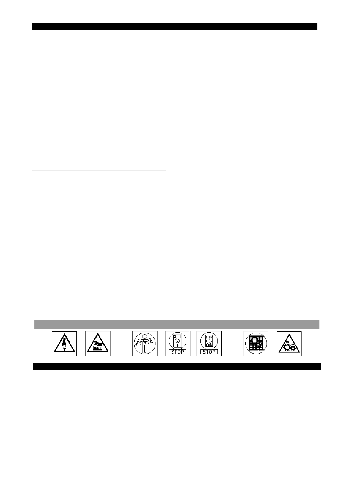
ENGLISH CHAPTER 4 ENGLISH
service of a competition technician.
4. Boiler safety valves (only for presses
fitted with an incorporated electric
boiler):check carefully its correct
working and that it does not vent steam.
In the case of a malfunction, replace the
whole safety valve: request the services
of a competent technician.
5. Also check the correct functioning of the
gauge, pressure gauge and pump.
c) If the press is fitted with a compressor, check
the oil level in the compressor head. If
necessary, top up the oil using a SAE 40 oil
(AGIP DICREA 150 or Q8 GREEN 150, or
similar). A change of oil is recommended
after a running in period of 100 working hours,
and then every 400 effective working hours.
In addition, clean the compressor head air
filter “POS. 4” (page 10-2) every 100 hours,
and replace it every 6 months.
SIX MONTHLY / YEARLY
MAINTENANCE
For machines with boiler:
a) Carefully clean the heating elements of any
scaling. This is of a great importance for the
performance of the boiler, and it is easy to
do. Simply remove the flange with the
heating elements and carefully clean them.
During this operation it is important to
disconnect the copper tube that connects
the pump to the boiler, and clean the joint,
where the water enters into the boiler, of
any deposits that may be obstructing it.
b) Check the various gaskets and gate valves
as continuous heating and cooling can
cause leaks. Should there be leaks, remove
remove the filter inside the solenoid valve and
clean the latter with compressed air.
d) Disconnect the copper pipes that connect the
gauge and the pressure gauge and clean
them internally to remove any scaling.
e) In case of boiler with the electronic level
control remove the probe and carefully clean
it of any sediment or scaling using an emery
cloth. Assuring that the spindle/ electrode
doesn't revolve in the sonde support body,
otherwise tighten the superior nut.
f) Carry out a visual inspection inside the boiler,
at least once a year, to control the conditions
of the inside walls and the presence of
possible scales and/or corrosions. Carefully
clean the inside of the pipe containing the
probe.
g) Disassemble the safety valve and clean the
joint, on which is assembled, of any scaling.
Also check that the valve is not obstructed.
For machine without boiler:
a) Clean the filter fitted on the condensation
return pipe that, if dirty, stops drainage and
allows the siphoning back of water.
For all the machines:
a) Check the condition of all the labels and
plates on the machine (warnings and
instructions). If they are in poor condition,
replace them.
b) Check the wear of the board padding and, if
necessary, substitute it. The board padding
is considered a part of the normal wear and
tear since ironing tends to matt the padding
and decreases the aspiration and steaming
capacities of the board.
the gaskets and gate valves and replace
with new to prevent further leaks.
c) Clean the water filter fitted to the feed
solenoid valve
. To do this, remove the sleeve,
BREAKDOWNS
Problem: Causes: Action:
IMMEDIATELY FOLLOWING INSTALLATION FOR MACHINES WITH BOILER
1. The orange warning light is
on, the pump works and
produces a strange noise
without stopping.
2. The boiler does not gain
pressure and orange warning
light is on.
1. Water is not reaching the
machine.
2. The drainage gate valve is not
tightly closed.
Page 4-6
1. Check the reason for the
water not reaching the
machine. Letting the pump run
without water will damage it
beyond repair.
2. Close the drainage gate valve.
ENGLISH CHAPTER 4 ENGLISH
IMMEDIATELY FOLLOWING INSTALLATION FOR MACHINES WITHOUT BOILER
1. The steam is wet after the
first few work cycles.
2. Insufficient steam. 2. Insufficient feed pressure.
1. Causes:
a) The drain has been
installed in the wrong
place.
b) The check valve has been
installed in the wrong
direction, or has not been
installed at all.
c) Water in the steam feed
pipe.
d) Siphoning in the
condensation return pipe.
1. Action:
a) Check that a steam trap is
mounted to the condensation return pipe or find a
better place to install it.
b) Check the check valve
flow direction, or install a
check valve.
c) Install a steam trap at the
end of the pipe between the
steam feed pipe and the
condensation return,or
better upstream of the
machine.
d) Eliminate the siphoning to
create a slope towards the
drain.
2. Check that the steam
generator produces steam at
4/6 bars (60-90 psi); if
necessary replace the steam
feed source.
IMMEDIATELY FOLLOWING INSTALLATION FOR MACHINES WITH AND WITHOUT
BOILER
1. Electrical control board off. 1. Wrong electrical connection. 1. Check that the electrical
supply line is correctly
connected to the electrical
connectors (see the
electrical circuit drawings),
and that current is at the
isolator.
2. The electrical warning lights
come on, but the upper
board does not lower, nor
2. The compressed air is not
arriving at the machine.
2. Check the compressed air
line.
does the machine produce
steam, or exhaust.
BREAKDOWNS ON THE BOILER AND ON THE ELECTRONIC LEVEL CONTROL
1. The water feeding valve is
open, but the electronic
station alarm is on.
2. Water is sucked back during
steam generation at ironing
start.
1. Water is not fed into the
boiler and the station is
signalling the error.
2. Causes:
a) The machines has not been
used for several hours.
b) The ball valve on the water
pipe was not closed on the
previous evening.
c) The
ball valve is out of
order and
does not close
properly.
1. Check that water is actually
fed into the machine and, if
necessary, clean the
passages as indicated at
Pos.5.
2. With the machine in operation,
drain water from the boiler by
opening the boiler drain ball
valve slowly until the pump
starts re-loading water. Now
close the drain cock.
Page 4-8

ENGLISH CHAPTER 4 ENGLISH
3. Water is sucked back during
steaming, even after having
restored the correct level (as
per Pos. 2).
3. Causes:
a) The electric feeding valve is
out of order or dirty, and
prevents the pin from
closing tight, water leaks in.
b) Water is not drained every
day from the boiler, and
foam develops.
c) The boiler level gauge has
lime scales (mostly on its
end): the machine does not
operate correctly and water
is fed in continuously.
d) Interruption on wires and on
connection contacts of the
level gauge on the electric
panel.
e) Electronic group failure.
3. Solutions:
a) Replace the water feeding
valve.
b) Remember to drain the
boiler every evening so as
keep it free from foam and
scales.
c) Disassemble the level
gauge and carefully remove
lime scales from the gauge
body by means of emery
cloth. Make sure that the
pin/electrode does not
rotate inside the gauge
holder, if necessary screw
the upper nut tight.
d) Restore continuity on wires
and connection contacts
between level gauge and
electric panel.
e) Replace the electronic
station inside the electric
panel.
4. No water in the boiler with
consequent heating elements
burning due to the failure of
the electronic level control
group.
4. If the correct water level into
the boiler is not restored in
20 seconds the electronic
group and the level gauge
automatically switch off the
4. Replace the level gauge or
the electronic group or both.
Performs the checking
procedure as per Pos. 3C.
heating elements, avoiding
to burn them. Obviously a
failure of the level gauge or
of the electronic group would
prevent this automatism and
would burn the heating
elements.
5. No water in the boiler due to
a failure of the water feeding
group (electric valve, tubes
and connections).
5. Causes:
a) No water from the feeding
system.
b) The water filter assembled
on the electric feed valve
is clogged.
c) Electric feed valve failure.
d) Lime scales clog tubes and
connections.
5. Solutions:
a) Make sure that water is
fed into the machine by
removing the rubber
pipe mounted on the
feeding pipe holder.
b) Clean the filter net by
disassembling the
rubber feed pipe holder.
c) Check if the coil of the
feed valve is burned, if
so replace it.
d) Free and clean tubes
and connections from
lime scales.
Page 4-9
 Loading...