

Page 1
Rev.1.20
(714)985-9286 Fax(714)985-9288
2700E.ImperialHwy.,SuiteN-Brea,CA92821
Page 2
1
SV203 - Servo Motor Controller Board
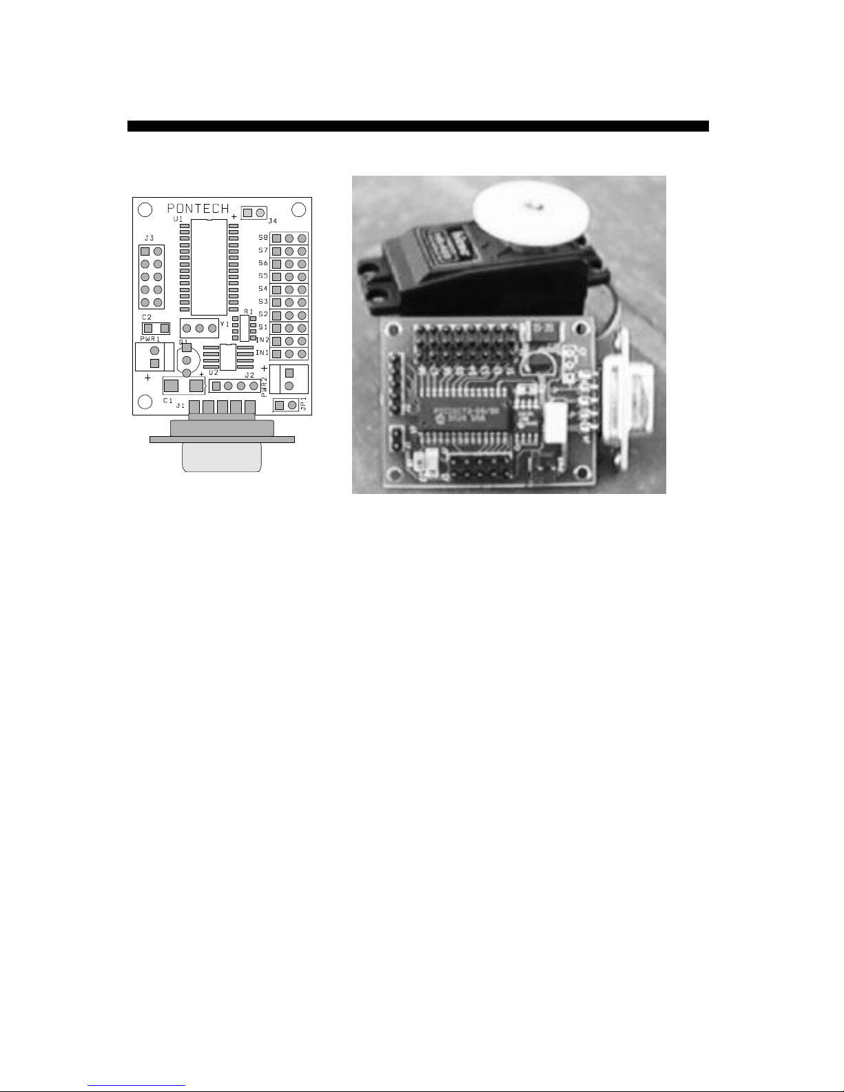
The SV203 is a PIC16C73 microcontroller based servo motor
controller board that accepts RS-232 serial data from a host
computer and outputs PWM (pulse-width-modulated) signals to
control up to eight RC (radio-controlled, i.e. model airplanes, cars,
etc.) servo motors. Unused servo pins can be reconfigured as digital
outputs for controlling on/off devices. LED displays can be driven
directly by the pins but devices such as relays and solenoids may
need a simple transistor driver circuit.
There is also a 5-channel A/D port for reading analog voltage
between 0-5 volts, and a SPI (synchronous peripheral interface)
port which allows data to be shifted in or out serially.
The SV203B/C has the added feature of being able to run a
standalone BASIC program stored on board an 8K EEPROM. An
optional IR-Receiver/Transmitter (IR100) is also available to allow
Infrared Serial Communications.
Page 3
2
SV203 - Servo Basics
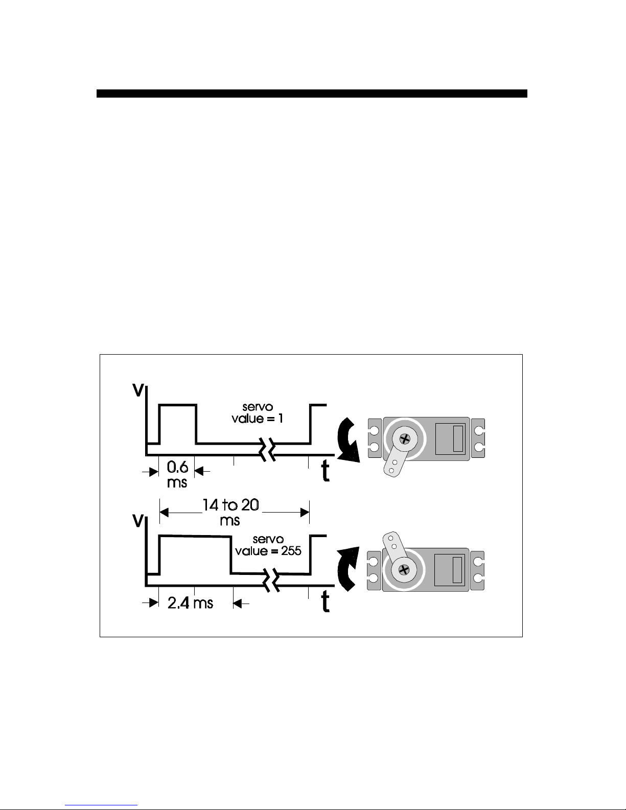
RC servos operate using feedback to compare the current position
to an input pulse width, which typically repeats every 14 to 20 ms
(milliseconds). If the pulse width lasts for approximately 0.6 ms, the
servo will rotate to a maximum position. If the pulse width is
increased to approximately 2.4 ms, the servo will rotate to the
opposite maximum position (Figure 1). A 1.5 ms pulse will set the
servo in the middle (neutral) position.
The SV203 controller is designed to the specifications of a Futaba
servo model FP-S148. These servos have a neutral position at 1.52
ms. -90 degrees at 0.6 ms, and 90 degrees at 2.4 ms. Other servos
may have slightly different values for these positions.
(Figure 1 - servo timing diagram)
Page 4
3
SV203 - Power Supply and Pin-out
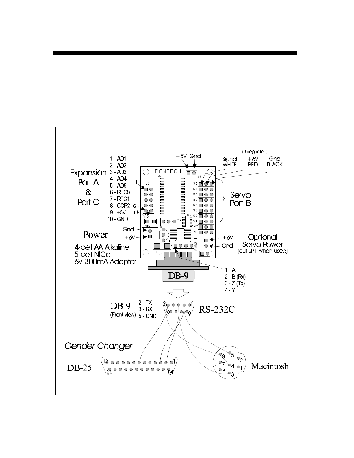
A 6-Volt DC source powers the board, either from 4 alkaline
batteries or 5 NiCad cells. An AC adapter can also be used: 6VDC,
at 300mA. If using NiCads, a 4-cell pack might be easier to find
than a 5-cell pack. The board will operate fine with 4 cells, but may
not last as long as 5 cells.
(Figure 2 - pin-out for SV203)
Page 5
4
SV203 - Power Supply and Pin-out
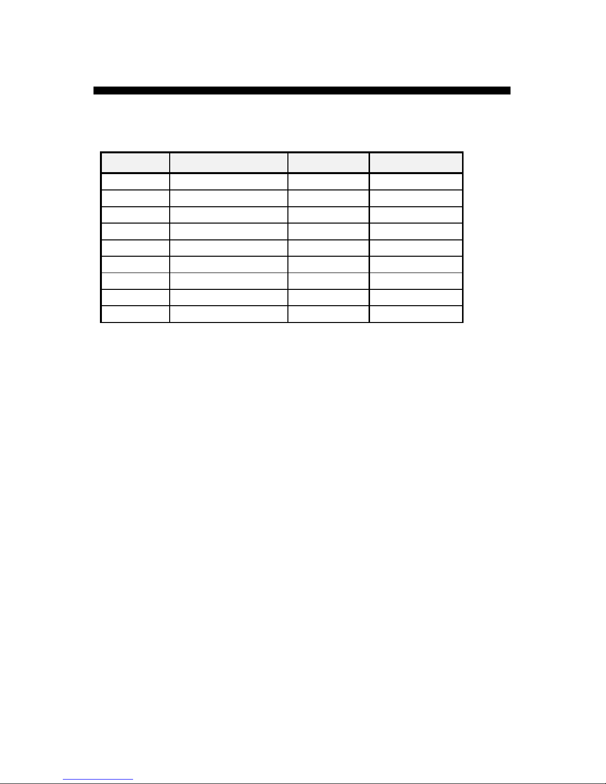
DB-9DB-9 DB-25DB-25 MacintoshMacintosh DB-9DB-9
1 -- 3 1
2 5 2 2
3 3 -- 3
4 -- -- 4
5 8 , 4 7 5
6 -- -- 6
7 -- -- 7
8 -- -- 8
9 -- -- 9
(Figure 2a – DB cross-referenced chart)
Page 6
5
SV203 - Servo Connections
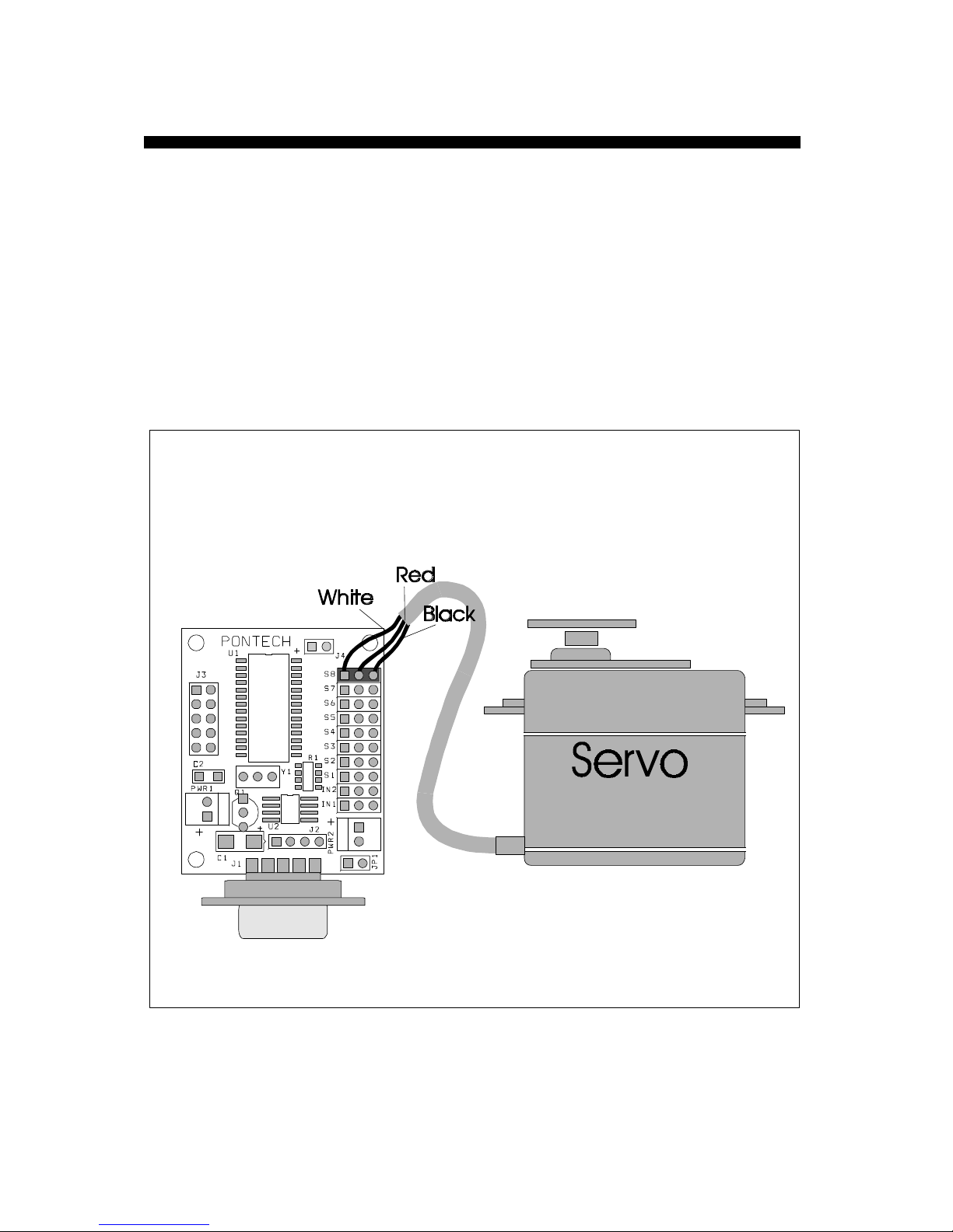
The servo port connectors use a 3-pin male sip (single inline pin)
connector (0.1-inch spacing). The servo connector is designed to be
used with Futaba-type servos with J-type connectors. The servos
have three colored wires, Black for ground, Red for power, and
White for signal.
Connect the cable with the White wire pointing to S1…S8, and the
Black wire toward the outside edge of the board.
(Figure 3 - servo connected to SV203)
Page 7
6
SV203 - Example Interface
OPEN “COM1:9600,N,8,1,CD0,CS0,DS0” FOR OUTPUT AS #1
DO
PRINT:PRINT “*****SV203 Servo Controller *****”
INPUT “Enter Board ID Number:
INPUT “Enter Servo # to control: Servo$
INPUT “Enter Position of Servo: Pos$
PRINT #1, “BD”;ID$;”SV”;Servo$;”M”;Pos$
INPUT “Quit (y/n)”; Q$: IF Q$ = “y” THEN EXIT DO
LOOP
(Listing 1 - Sample interface program using QBASIC)
***** SV203 Servo Controller *****”
Enter Board ID Number:? 1 Board width ID = 1
Enter Servo # to control:? 2 move servo #2 to
Enter Position of Servo:? 200 position 200
Quit (y/n):? n
***** SV203 Servo Controller *****”
Enter Board ID Number:? 0 Any Board regardless of
Enter Servo # to control:? 4 ID, move Servo #4 to
Enter Position of Servo:? 254 position 254
Quit (y/n):? n
***** SV203 Servo Controller *****”
Enter Board ID Number:? 1 Board with ID = 1
Enter Servo # to control:? 2 Turn off Servo #2
Enter Position of Servo:? 0
Quit (y/n):? n
***** SV203 Servo Controller *****”
Enter Board ID Number:? 1 This command is invalid because
Enter Servo # to control:? 9 there is no Servo #9 and also
Enter Position of Servo:? 256 256 is out of the range of the
Quit (y/n):? y servo position.
(Listing 2 - Example screen of when program in Listing 1 is running)
Listing 1 is a simple program written in QBASIC that requests the
user to input a board ID number, a servo number to control, and
the position of the servo.
Page 8

7
SV203 - Operation of Board
Connect the servos to the board, plug in the RS-232 cable to a
COM port of a PC and the other end to the SV203. Power the
board and the servos should return to the neutral position. Run the
example programs.
The SV203 processes information one ASCII string command at a
time. Each command string follows the format:
L n L n … <enter> (maximum of 20 characters/line)
Where L is the command letter(s) in caps, n is a decimal integer
number(s), and <enter> is ASCII 13. Please refer to Command
Listing Page (p.26) for a complete listing.
For example, the commands to select a board, select a servo and
move to a position are BD, SV, and M, respectively. If your want
to move servo #3 of a board with an ID number equal to 1 to
position 85, you would send the flowing command string.
BD1SV3M85 <enter>
The commands can also be separated by spaces or commas for ease
of reading.
BD1 SV3 M85 <enter> or
BD1,SV3,M85 <enter> or
BD 1 SV 3 M 85 <enter>
A terminal program may be used to test the functions of the board.
The default setting on the board is 9600 baud, N81, with echo off.
(A program called TERM.EXE is provided as a simple terminal like
software to test the SV203 functions).
Page 9

8
SV203 - Operation of Board
Once a board or servo is selected, it will stay selected until power is
removed or another select command is received. For example, if the
following commands were sent:
BD1 SV2 M100 <enter>
The next command will still move servo #2:
M150 <enter>
More then one servo can be moved at the same time in one line of a
command string, just make sure you don’t exceed the 20 characters
per line limit, including spaces and commas:
BD1 SV1 M30 SV2 M104 SV3 M25 <enter>
The commands above will select Board #1, Move servo #1 to
position 30, then move servo #2 to position 104 and move servo #3
to position 25 all at about the same time.
Any parameter value for the command not in the range of the
command will be ignored. (see Command Listing Page – p.26.)
The board will start processing the command string when it
receives the <enter> or ASCII 13 character. The host computer
talking to the board should insert a delay of about 3 milliseconds
between each command string to allow time to process the
commands.
Page 10

9
SV203 - Commands Descriptions
BDn Select Board
Before the board will accept any commands, it must first be
enabled. To enable the board, you must send the BD command
followed by the board ID number (n). The default ID number of the
board is 1. So simply send the following to enable the board:
BD1 <enter>
The board ID number can be user-redefined by using the WE
command (see Commands Descriptions Page – p.20). This allows
multiple boards of different ID number to be connected to the same
serial port.
You can enable the board in two other ways: You can pre-enable
the board at power-up by changing the default settings. (see
Changing Default Settings Page – p.22); or you can enable the
board by sending an ID number 0, such as:
BD0 <enter>
This will override the ID number checking and any boards
connected to the port will be enabled regardless of the ID number
of the board.
Page 11

10
SV203 - Commands Descriptions
SVn Select Servo
On power-up, servo #1 is pre-selected. To select another servo or
to make sure the servo is selected, send “SV” followed by the servo
number. The servo number must be between 1 and 8 because there
is a maximum of eight servos that the board can control.
i.e. SV3 <enter>
servo #3 will be selected. Any move commands that follow
will operate on servo #3.
Page 12
11
SV203 - Commands Descriptions
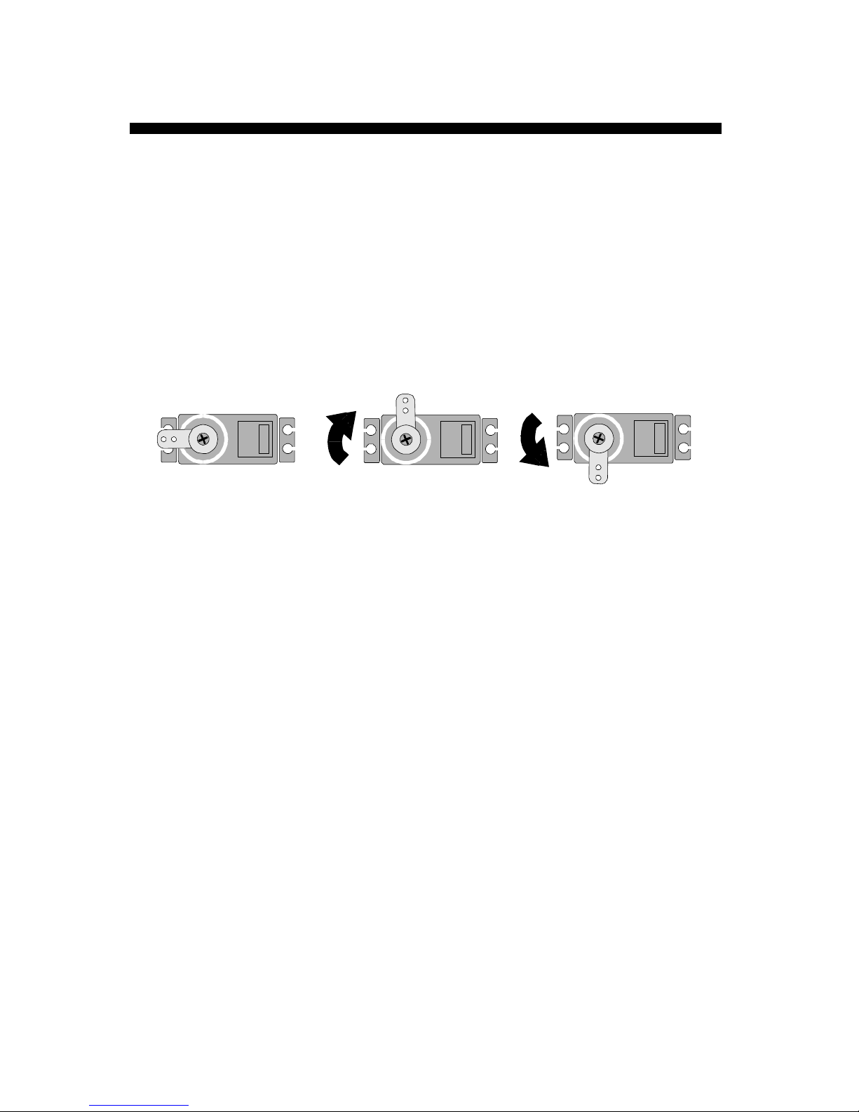
Mn Move to absolute position
This command will move the selected servo to an absolute position.
The range of the position is between 1 and 255. On a RC-type
servo, the maximum mechanical movement is about 180 degrees.
The 1 to 255 position ranges gives a precision of a little under one
degree. The figure below shows what position the servo will be in
given the value of position.
M128 M1 M255
Sending a zero to the servo can turn off the pulse-width command
signal to the servo, which causes the servo to remove power from
the motor:
M0 <enter>
Page 13

12
SV203 - Commands Descriptions
In Incremental move relative to current position
This command will move the servo relative to the current position
of the servo by adding or subtracting the value entered to the
current servo position.
i.e. M100 <enter>
I10 <enter>
I-20 <enter>
The selected servo will first move to position 100, then to
position 110 (100+10), and then finally to position 90
((100+10) - 20).
Page 14

13
SV203 - Commands Descriptions
Dn Delay/Pause in milliseconds (ms)
Delay commands may be added to the string to pause between
movements:
SV1 M20 D1000 M100 <enter>
servo #1 will move to position 20. There is a one-second (1000 ms)
pause, and then servo #1 will move to position 100.
Caution: When using the Delay command, the board will not
receive input from the serial port during the delay state. The host
computer that is talking to the board has to wait at least the same
amount of time before another command string can be sent. Any
commands sent during the delay will be ignored.
Page 15
14
SV203 - Commands Descriptions
PSn Pin Set
PCn Pin Clear
PTn Pin Toggle
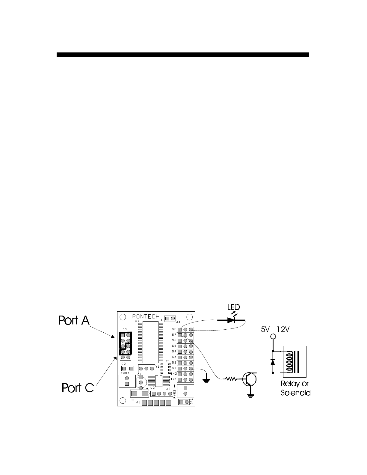
These commands allow you to use the servo port as a digital output
by setting, clearing or toggling individual bits of the servo port. In
order to use the port as a digital output, the servo PWM must first
be turned off by sending a M0 command to each servo pin that you
want to use as digital output.
i.e. SV7 M0 PS7 <enter>
Pin S7 of the servo port will be set high (5 Volts).
i.e. SV8 M0 <enter>
PT8 <enter>
Pin S8 of the servo port will be toggled/flipped
(set high if pin was low, or cleared if pin was high).
The pins can drive and sink up to 25 mA, a driver circuit such as
the one below may be required to drive anything that uses more
current such as a relay or a solenoid.
Page 16
15
SV203 - Commands Descriptions
ADn Read a voltage on the A/D port
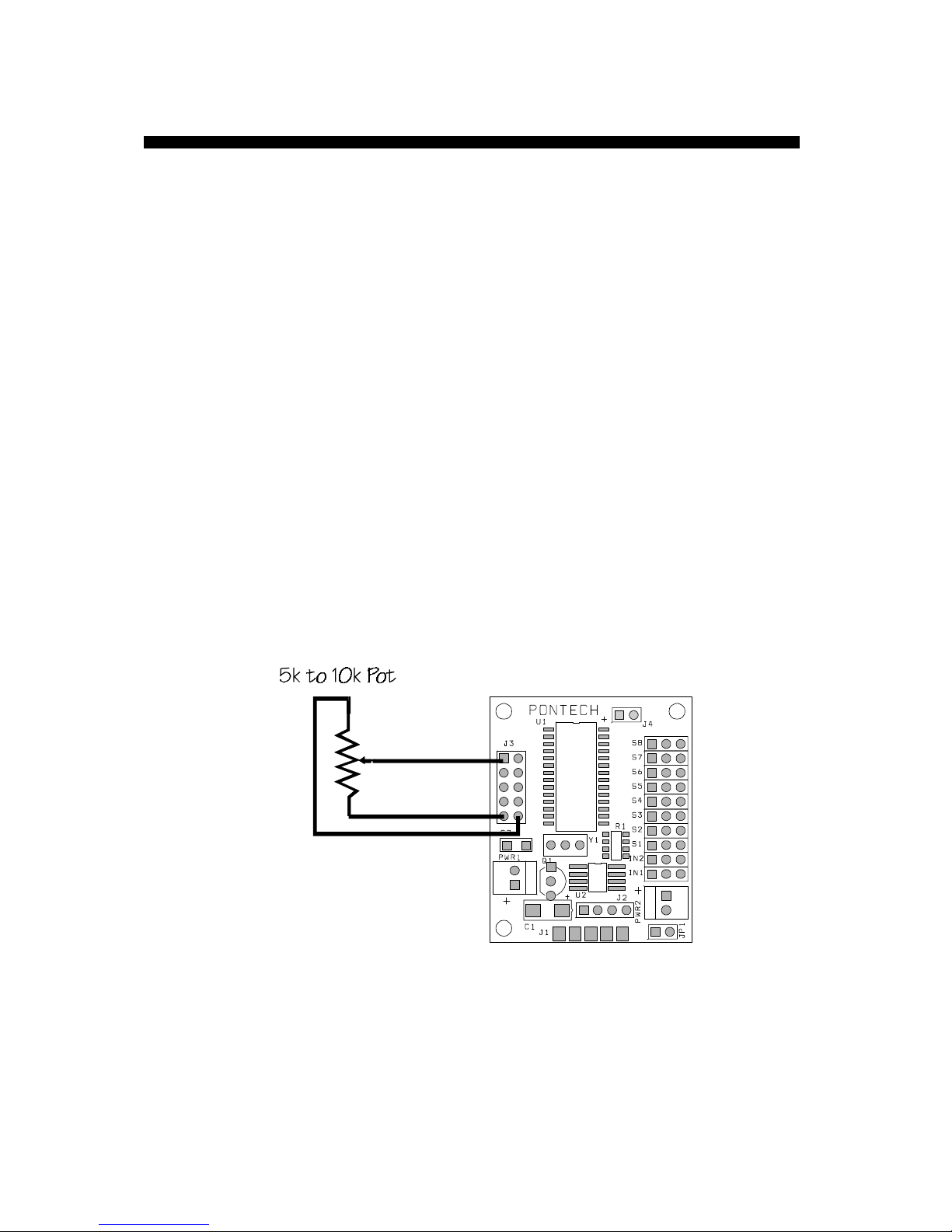
Port A (see figure on previous page) is a 5-Channel, 8-bit A/D
input that can read an analog voltage. The n is a number between 1
to 5, which tells which pin on the A/D port to request. When the
board receives this command, it will read the specified voltage on
the pin and return a value between 0 to 255, which represents a
voltage between 0 to 5 Volts.
i.e. AD1 <enter>
If wires were connected as in the figure below and the
potentiometer as in the middle position, the board would
return a value close to 28 followed by <ASCII 13>, which is
about 2.5 Volts.
Page 17
16
SV203 - Commands Descriptions
SI, SOn Shift byte In/Out the SPI port
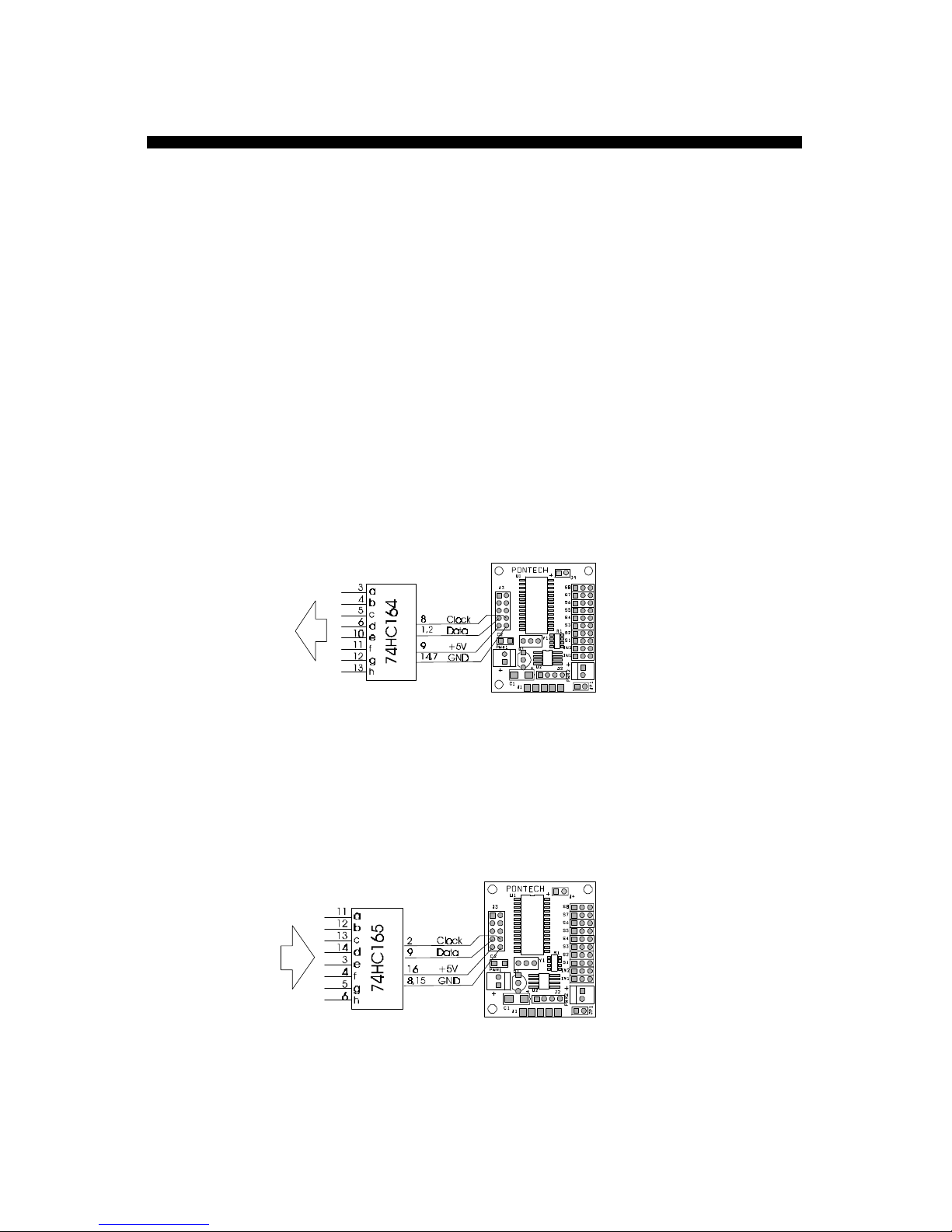
These commands allow you to use Port C (see figure on p.14) on
the board as a synchronous serial port to shift in or out a byte of
data. The figure below shows how to connect shift register chips
(74HC164 or 74HC165) to the board to make a serial-to-parallel or
parallel-to- serial converter.
Use the SO command to make a serial-to-parallel converter
i.e. SO3 <enter>
pins 3 and 4 of the ‘164 will be set high, while all others are
low (3 decimal à 00000011 binary).
Use the SI command to make a parallel-to-serial converter
i.e. SI <enter>
the board will return a number between 0 to 255.
Page 18
17
SV203 - Commands Descriptions
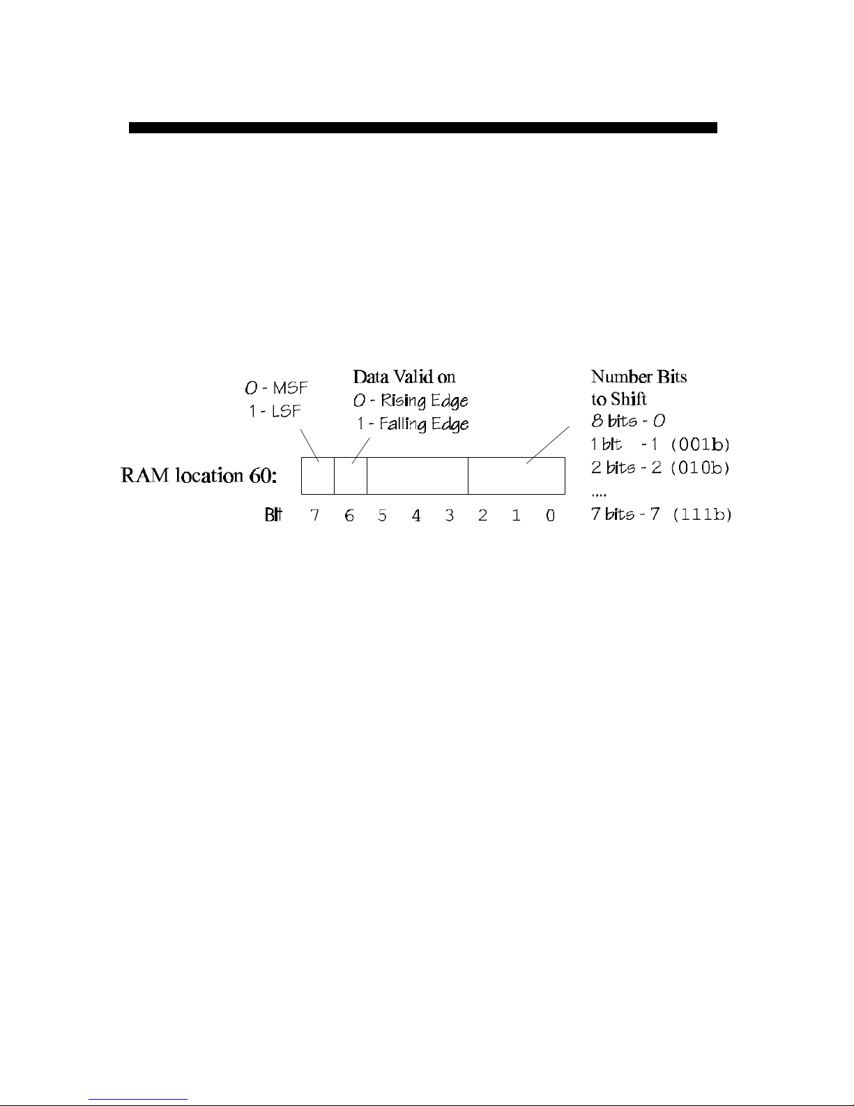
There is a configuration register at location 60 in RAM. The value
of the register is initialized by the contents of EEPROM in location
11. The register configures the shift function for MSF (most
significant first) or LSF (least significant first), data valid on clock
going high or low, and the number of bits to shift in/out.
Page 19

18
SV203 - Commands Descriptions
WRm n Write to RAM
RRm Read from RAM
where m is the memory address (see table on next page),
n is the value to be stored.
These commands allow you to modify and read the contents of the
internal register or RAM of the processor. The internal RAM is a
volatile memory storage, so when power is removed the contents
will be erased.
i.e. WR51 20 <enter>
servo #1 will move to position 20, this command is
equivalent to SV1 M20 <enter>
i.e. RR52 <enter>
the position of servo #2 will be returned.
Page 20
19
SV203 - Commands Descriptions
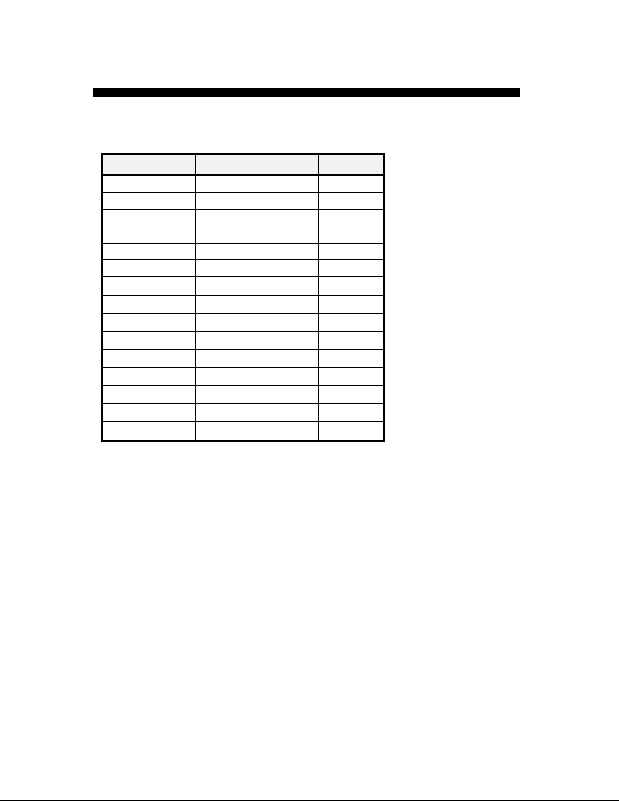
RAM Memory Map:
Address (m)Address (m) UsageUsage NoteNote
5 Port A
6 Port B
7 Port C
14 TMR1L
15 TMR1H
16 T1CON
27 CCPR2L
28 CCPR2H
29 CCP2CON
51 to 58 Current Servo Position
59 Servo Select
60 Shift Config Register
133 TRIS A
134 TRIS B
135 TRIS C
Note: All other RAM locations not listed are used by the
system and should not be used.
Page 21

20
SV203 - Commands Descriptions
WEm n Write to EEPROM
REm Read from EEPROM
where m is the memory address (see table on next page),
n is the value to be stored.
These commands allow you to modify and read the contents of the
external EEPROM connected to the processor. The EEPROM is a
non-volatile memory storage, so any information written to it will
stay even when power is removed.
i.e. WE0 2 <enter>
change the board ID number to #2
i.e. RE1 <enter>
the SV203 returns the initial servo value of servo #1
Page 22
21
SV203 - Commands Descriptions
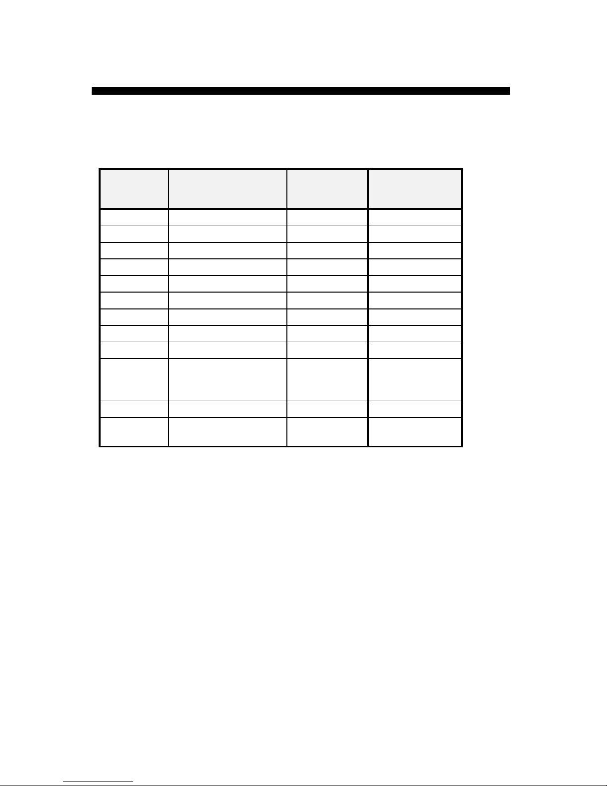
EEPROM Memory Map:
AddressAddress
(m)(m)
UsageUsage FactoryFactory
default default
NoteNote
0 Board ID # 1
1 Initial Servo #1 Value 128 0 - off or Digital
2 Initial Servo #2 Value 128 0 - off or Digital
3 Initial Servo #3 Value 128 0 - off or Digital
4 Initial Servo #4 Value 128 0 - off or Digital
5 Initial Servo #5 Value 128 0 - off or Digital
6 Initial Servo #6 Value 128 0 - off or Digital
7 Initial Servo #7 Value 128 0 - off or Digital
8 Initial Servo #8 Value 128 0 - off or Digital
9 Baud Rate 50 (9600 baud) 24 (19200 baud)
100(4800 baud)
200(2400 baud)
10 Pre Enable Flag 1 1-Yes 0-No
11 Shift Config Register 0 MSB, valid on
Rising, 8-bit
Page 23

22
SV203 - Changing Default Settings
When the board is powered-up, it first reads the external EEPROM
to get its Board ID number, Initial positions for the servo, Baud
rate, and some other initial flags. These initial settings can be
changed by using the WE command (for WE command see p.20).
To change ID:
i.e. WE0 3 <enter>
#3 is the new ID number
To have the board be pre-enable on power-up:
i.e. WE10 1 <enter>
To change Servo initialization:
i.e. WE2 0 <enter>
Servo #2 will be off when the board is turned on.
See the Memory Map on previous page for other default settings.
Page 24
23
SV203 – Changing Default Settings
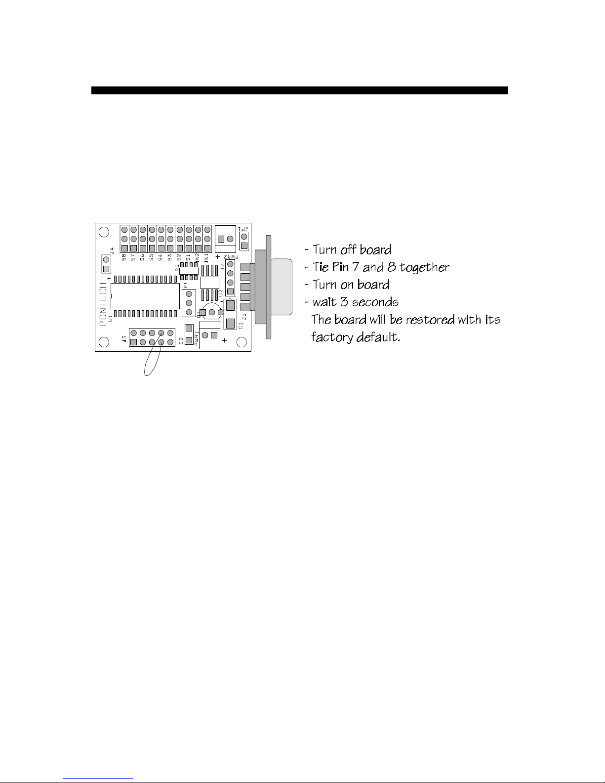
The board can be reset to its factory default settings by tying pins 7
and 8 of Port C together, power-up the board, and wait for about 3
seconds.
You can also use the enclosed program on disk called
DEFAULT.EXE to reset the default settings of the board.
If the baud rate of the SV203 has been altered, either on purpose or
inadvertently, the DEFAULT.EXE program cannot be used. In this
case, the above method of shorting pins 7 and 8 of connector J3 is
preferred.
Page 25
24
SV203 - Controlling Multiple Boards
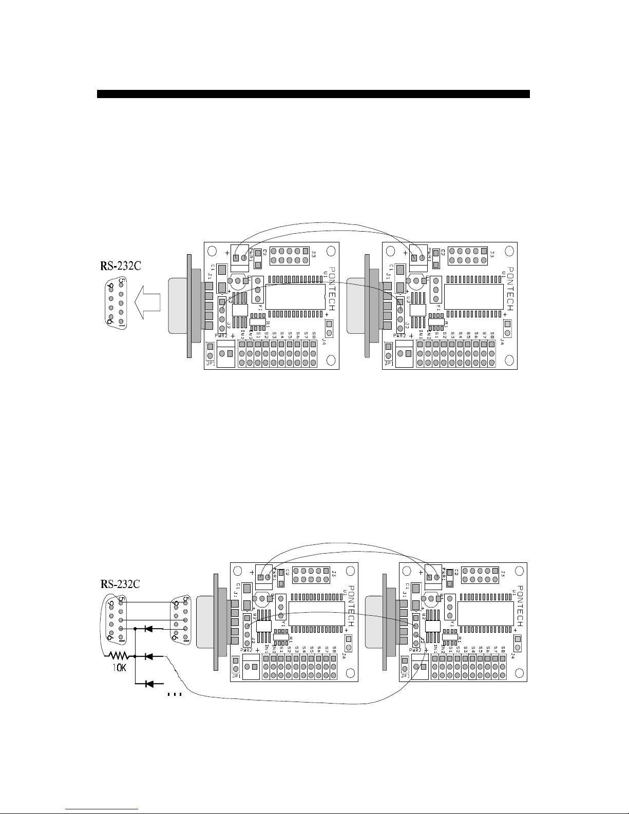
You can connect multiple boards to the same serial line by
reassigning different ID numbers to each board.
If you are using the second board for output only, the wiring below
will work just fine.
If the other boards need to be used for both input and output then
use the wiring below. Since the RS232C standard is designed for a
single peripheral, the output pin of the boards cannot be tied
directly together.
Page 26

25
SV203 - Notes
______________________________________________
______________________________________________
______________________________________________
______________________________________________
______________________________________________
______________________________________________
______________________________________________
______________________________________________
______________________________________________
______________________________________________
______________________________________________
______________________________________________
______________________________________________
______________________________________________
______________________________________________
______________________________________________
______________________________________________
______________________________________________
______________________________________________
______________________________________________
______________________________________________
______________________________________________
______________________________________________
______________________________________________
______________________________________________
______________________________________________
___________________
Page 27
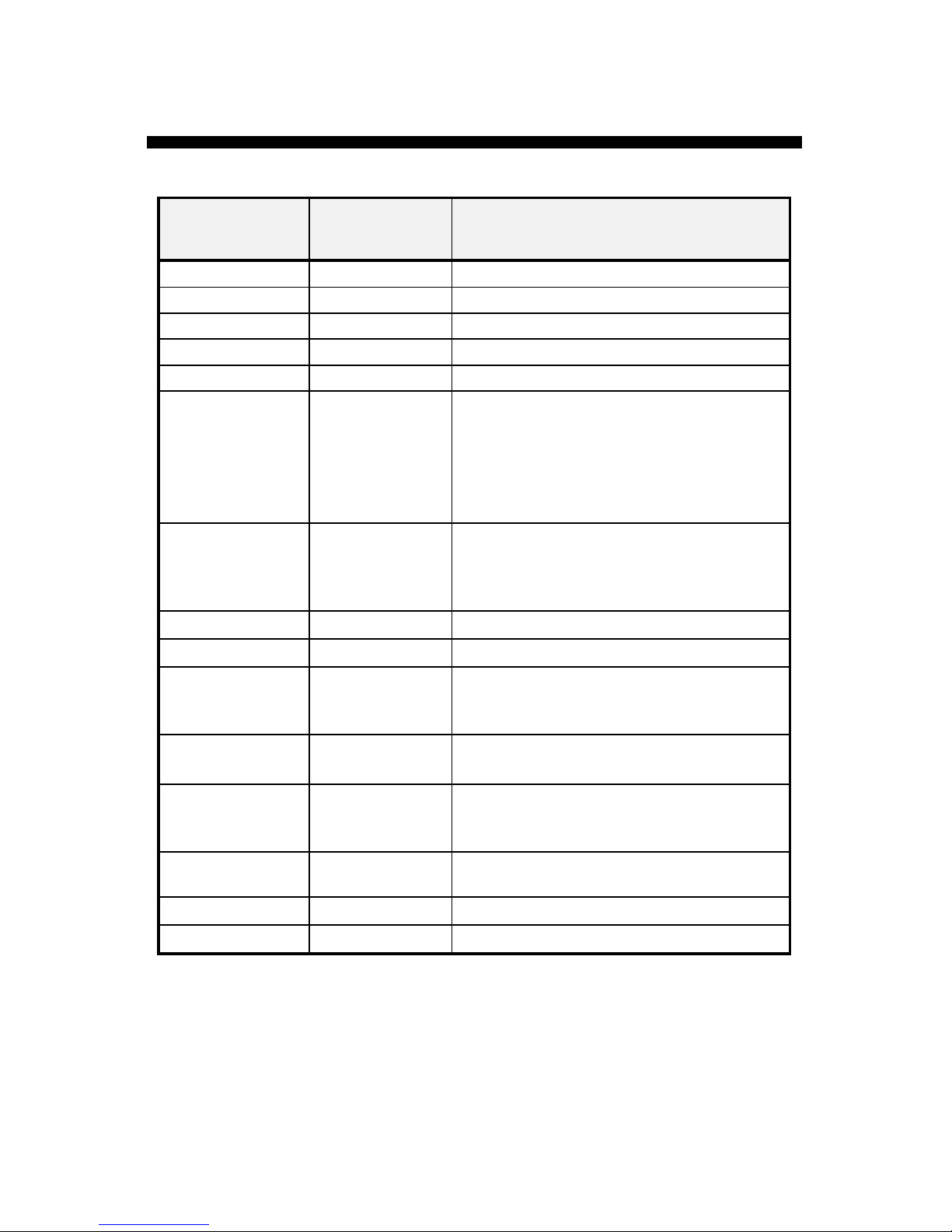
26
SV203 - Commands Listing
CommandsCommands ParameterParameter
(n)(n)
DescriptionDescription
BDn
0 to 255 Board Select
SVn
1 to 8 Servo Select
Mn
0 to 255 Move to an absolute location
In
-128 to 127 Move relative to current position
Dn
1 to 65535 Delay (ms)
PSn
PCn
PTn
1 to 8 Put, set single pin of servo port
b is a number between 1 and 8, which tells
what pin on the port is being used.
If n = 0 à clear Bit
n = 1 à Set Bit
n = 2 à Toggle Bit
ADn
1 to 5 Get A/D value, the board will return a value
between “0” to “255” followed by ASCII 13
which represent a voltage between 0 to 5
Volts.
SOn
0 to 255 Shift a byte out to the SPI port
SI
None Shift a byte in form the SPI port
WRm n
m = 0 to 255
n = 0 to 255
Write to internal RAM
m is the memory location
n is the value to write
RRm
m = 0 to 255 Read the contain of internal RAM
m is the memory location to read
WEm n
m = 0 to 8190
n = 0 to 255
Write to external EEPROM
m is the memory location
n is the value to write
REm
m = 0 to 8190 Read the contents of external EEPROM
m is the memory location to read
?
None Help, return summary of command listing
V?
None Returns the firmware version
Page 28
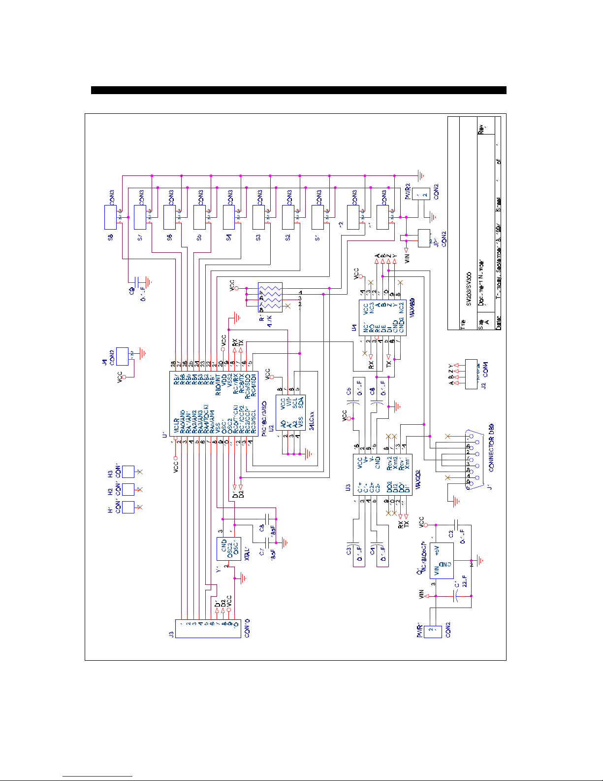
27
SV203 - Schematic
Page 29

28
SV203 - Warranty and Copyrights
Warranty
Pontech warrants its products against defects in materials and workmanship for
a period of 90 days.
If you discover a defect, Pontech will, at its option, repair, replace, or refund
the purchase price. Simply return the product with a description of the problem
and a copy of your invoice (if you do not have your invoice, please include your
name and telephone number).
The warranty does no apply if product has been damaged by accident, abuse, or
misuse.
Copyright and Trademarks
Copyright © 1997-98 by Pontech. All rights reserved.
PIC is a registered trademark of Microchip Technology, Inc.
FUTABA is a registered trademark of FUTABA Corporations.
Disclaimer of Liability
Pontech is not responsible for special, incidental, or consequential damages
resulting from any breach of warranty, or under any legal theory, including lost
profits, downtime, goodwill, damage to or replacement of property, and any
costs or recovering, reprogramming, or reproducing and data stored in or used
with Pontech products.
Page 30

Copyright1997-98byPontech.Allrightsreserved.
 Loading...