

Ponovo PW636i Hardware Instruction Manual
PW636i Hardware Instruction Manual
1
PONOVO POWER CO., LTD
2F, 4Cell, Tower C, In.Do Mansion
No.48A Zhichun Road, Haidian District
Beijing, China (Post Code 100098)
Office
TEL. +86 (10) 82755151 ext. 8887
FAX +86 (10) 82755257
E-Mail Info@ponovo.com.cn
Website www.ponovo.com.cn
PW636i
HARDWARE INSTRUCTION MANUAL
VERSION: PW636i-AE-2.03
DATE : 21/09/2011
This manual is the publisher of PONOVO POWER CO., LTD. To make any kind of copy of this
manual please contact PONOVO POWER CO., LTD in advance.
This manual represents the technical status for the moment of publishing. The product information,
description and specifications mentioned in the manual do not have any contact binding force and
PONOVO POWER CO., LTD remains the right to make modifications to the technical
specifications and configurations without prior notice. PONOVO POWER does not take
responsibility to the possible error/mistakes in this manual.

PW636i Hardware Instruction Manual
2
1. Preface ……………………… 3
2. Safety precaution …………. 4
3. Designed applications …… 5
3.1 Product features …………… 5
4. Operation preparation …… 6
4.1 Preparation …………………. 6
4.2 Connecting PC …………….. 6
5. General description ……… 7
5.1 Block diagram ……………… 7
5.2 DSP card …………………… 8
5.3 Front panel …………………. 8
5.4 Ethernet port ………………… 8
5.5 Current booster interface ….. 9
5.6 Pause button ………………… 10
5.7 LED indication ………………. 10
5.8 Rear panel…………………….. 12
5.9 External amplifier and low
level output interface………... 13
5.10 GPS interface ………………… 14
5.11 Multi-kits synchronization
interface ………………………. 15
5.12 IP reset ……………………….. 16
6. Hardware configuration …… 17
6.1 Current generators …………. 17
6.2 Current output configuration
in 3 current mode ……………. 17
6.3 Current in series connection in 3
current mode ………………… 19
6.4 Voltage generators ………….. 19
6.5 Connect two voltage
generators in series..………. 19
7. Binary inputs and outputs ….. 21
7.1 General Description …………. 21
7.2 Binary Input…………. …………. 21
7.3 Polarity of Binary Inputs …….. 22
7.4 Binary configuration…….. …….. 22
7.5 Isolation of Binary Inputs …….. 22
7.6 Threshold for Binary Inputs ….. 22
7.7 Binary Outputs ………………… 23
8. Getting ready for PC
controlled operation ………… 24
8.1 General description …………… 24
8.2 Set IP address ……….……… 24
8.3 Steps for setting IP address
in PC …………………………... 24
9. PW636i0-Related Products and
Accessories……………………...27
9.1 Analog Recording Unit
AR-10/AR-7D ………………………. ..28
9.2 PGPS02-GPS-based Synchronization
device …….………………………… ….29
9.3 PIRIG-B Based Synchronization
device…………………………………….29
9.4 PSS01 Circuit Breaker Simulator…30
9.5 Phpc01 Current Booster……………30
9.6 PACB108 scanning head…………..31
9.7 Low Level Output and Counter Input
Cable…….……………………………….31
9.8 Synchronization Control Cable… …31
9.9 Fiber Optic Cable……………………31
9.10 Standard Accessories...…………..31
9.10.1 Soft Bag for Test Lead……….32
9.10.2 Transportation Case…….……39
10. Specifications……….……………40
11. Appendix…….……….……………43
Contents

PW636i Hardware Instruction Manual
3
This manual gives detailed introduction to
PW636i so that user can have the reasonable,
effective and safe operation of this test kit.
This manual mainly consists of the following
parts:
Equipment and functions:
This part describes the main hardware parts
and their functions.
Panel description
This part describes the interfaces on the
panels and their applications
Technical specifications
This part describes the technical specifications
Optional accessories
This part describes the optional accessories
which will be used for dedicated applications
At the test site user should also refer to other
safety and test regulations required by his
management authorities.
This test equipment must be operated by
professional test people and careful reading of
this manual is required before operating this
test equipment.
The complete test system consists of PW636i
test equipment (used for generating analog
test signals), PowerTest test software,
Computer which has installed PowerTest
software, Test Leads/cables, etc. This manual
gives only the description to the hardware part.
Please refer to PowerTest software user
manual or PowerTest online help for details of
the software.
1.Preface

PW636i Hardware Instruction Manual
4
1. In case the power outlet for powering up the PW636i dose not have protective ground
customer must connect the ground socket of PW636i to the protective ground at the
test site
2. Please turn off the output before connecting/disconnecting the test object
3. The voltage output of over 36V is considered as dangerous and care must be taken
4. It’s not allowed to feed external voltage into the voltage/current output sockets
5. It’s not allowed to feed external current into the current/voltage output sockets
6. Disconnect the external circuit from the relay to avoid any influence to the test
7. Do not block the ventilation outlets
8. Avoid the equipment to be wet by rain
9. Do not switch-on and operate the equipment in the place having explosive gas or
water vapor
10. The 500V dangerous voltage can be in the equipment and please don’t remove the
cover by yourself
11. Please contact the manufacture for any maintenance
12. The guarantee will become invalid if PW636i is opened by the customer
2.Safety precaution

PW636i Hardware Instruction Manual
5
PW636i can be used by power plants,
substations, and relay manufactures, etc, for
the following test applications.
1. Test protective relays
2. Test transducers
3. Test energy meters
With optional AR-7D or AR-10 analog
recording unit the PW636i can even be used
for analog waveform analysis.
Product features
1. Output sources
6×32A current sources in two groups
4×300V voltage sources
2. Binary inputs
8 binary inputs for potential free or
potential contacts
3. Counter inputs
4 high speed counter inputs
4. DC measuring inputs
2 DC measuring inputs for testing
transducers
5. Binary outputs
8 binary inputs in two groups, 4 of dry
contact type and 4 of semiconductor
type
6. Low level outputs
12 low level outputs used for driving
external amplifiers or testing
Rogowski principle based relay
7. External amplifiers interface
8. GPS interface
Can receive GPS pulse signal from
optional PGPS02
9. Synchronized control interface
Used for synchronizing several
PW636i for specialized test purpose
10. Current booster interface (optional)
Used for increasing the compliance
voltage of current output for testing
high burden relays
11. AR-7D/AR-10 analog recording unit
(optional)
3.Designed applications
PW636i Hardware Instruction Manual
6
Preparation
Be sure that the following preparation/system
components are ready before operating the
test equipment:
PW636i test equipment
Main supply cable (delivered)
LAN control cable (delivered)
PC with PowerTest software properly
installed
Test leads connected to the test object
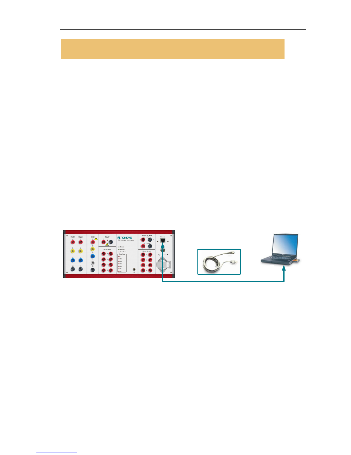
Connecting PC
1. Connect the LAN cable between PC and PW636i
2. Connect the power cables for PC and PW636i
3. Connect PW636i ground socket to the protective ground
4. Power on the PC and PW636i
5. Run PowerTest software
4.Operation preparation
PW636i Hardware Instruction Manual
7
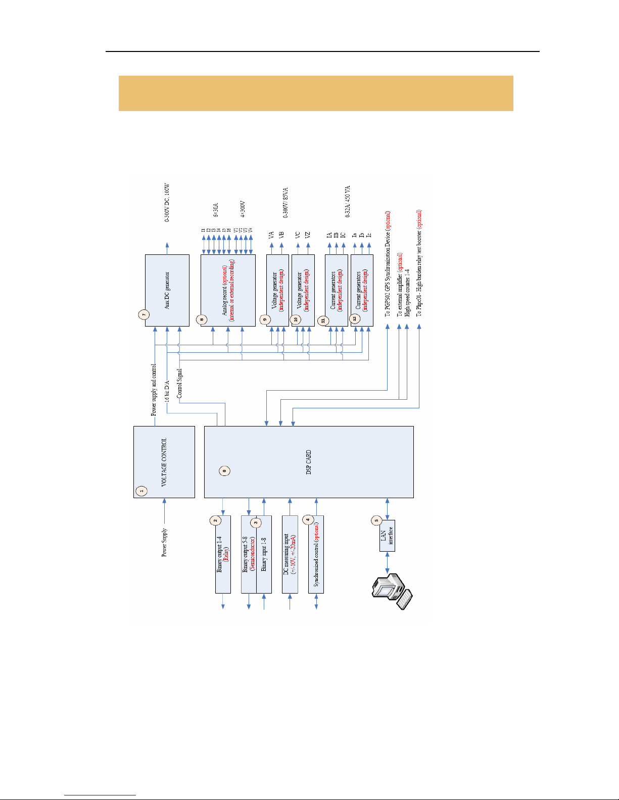
Block diagram
5.General description
PW636i Hardware Instruction Manual
8
DSP card
High performance DSP (digital signal processor) is used on the DSP card to ensure the accurate
and fast signal generation.
To get the satisfied accuracy and resolution the 32 bit D/A data converting technology is applied.
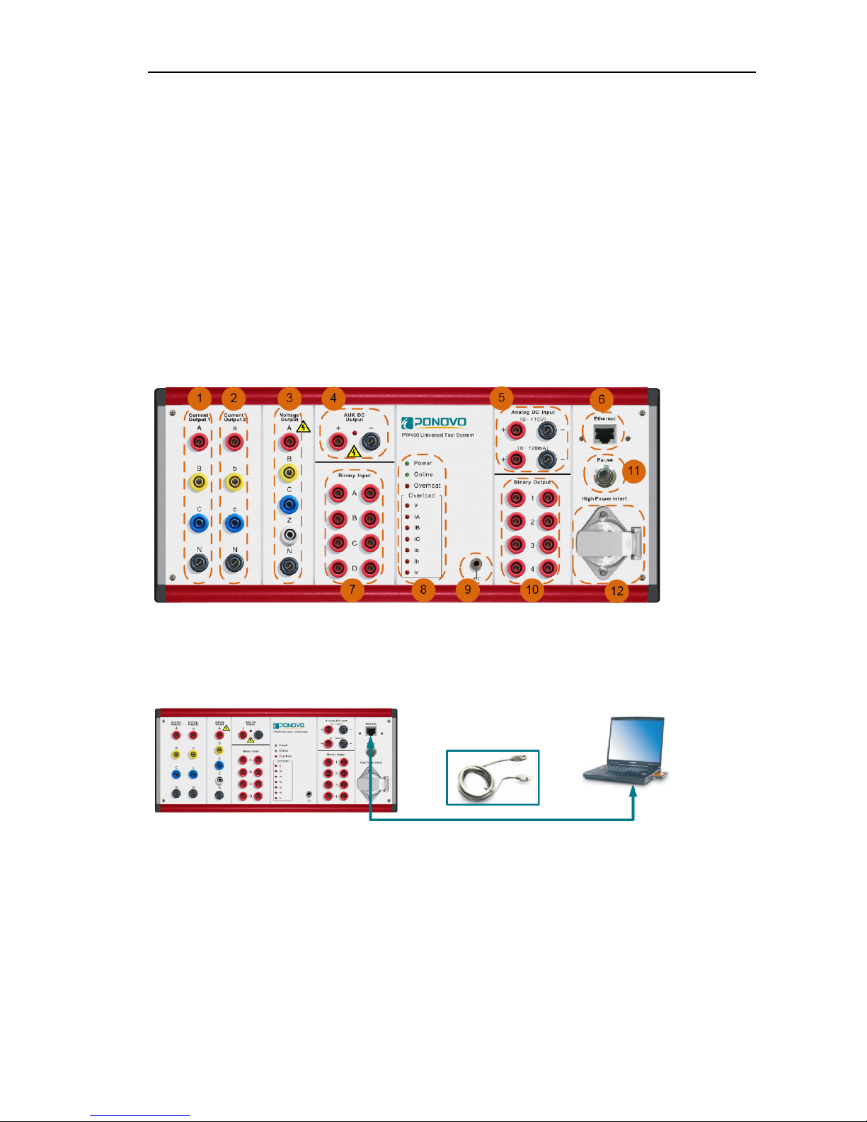
Front panel
1. Current output group 1
2. Current output group 2
3. Voltage output
4. Auxiliary DC
5. DC measuring input
6. RJ45 Ethernet PC control port
7. Binary input group 1
8. LED indication
9. Earth socket
10. Binary output group 1
11. Pause button
12. Current booster interface
Ethernet port
The Ethernet port is used to connect to external PC via Ethernet control cable.
Please refer to “Getting ready for connecting to PC” for details
PW636i Hardware Instruction Manual
9
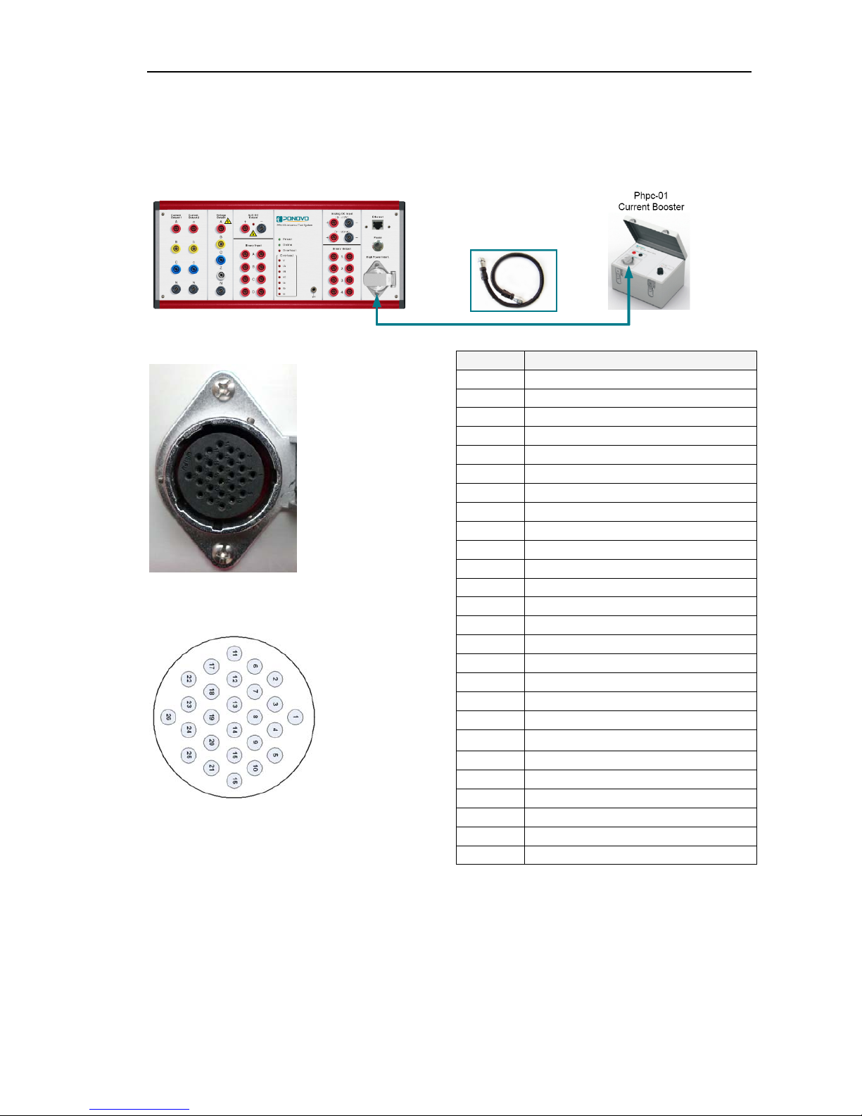
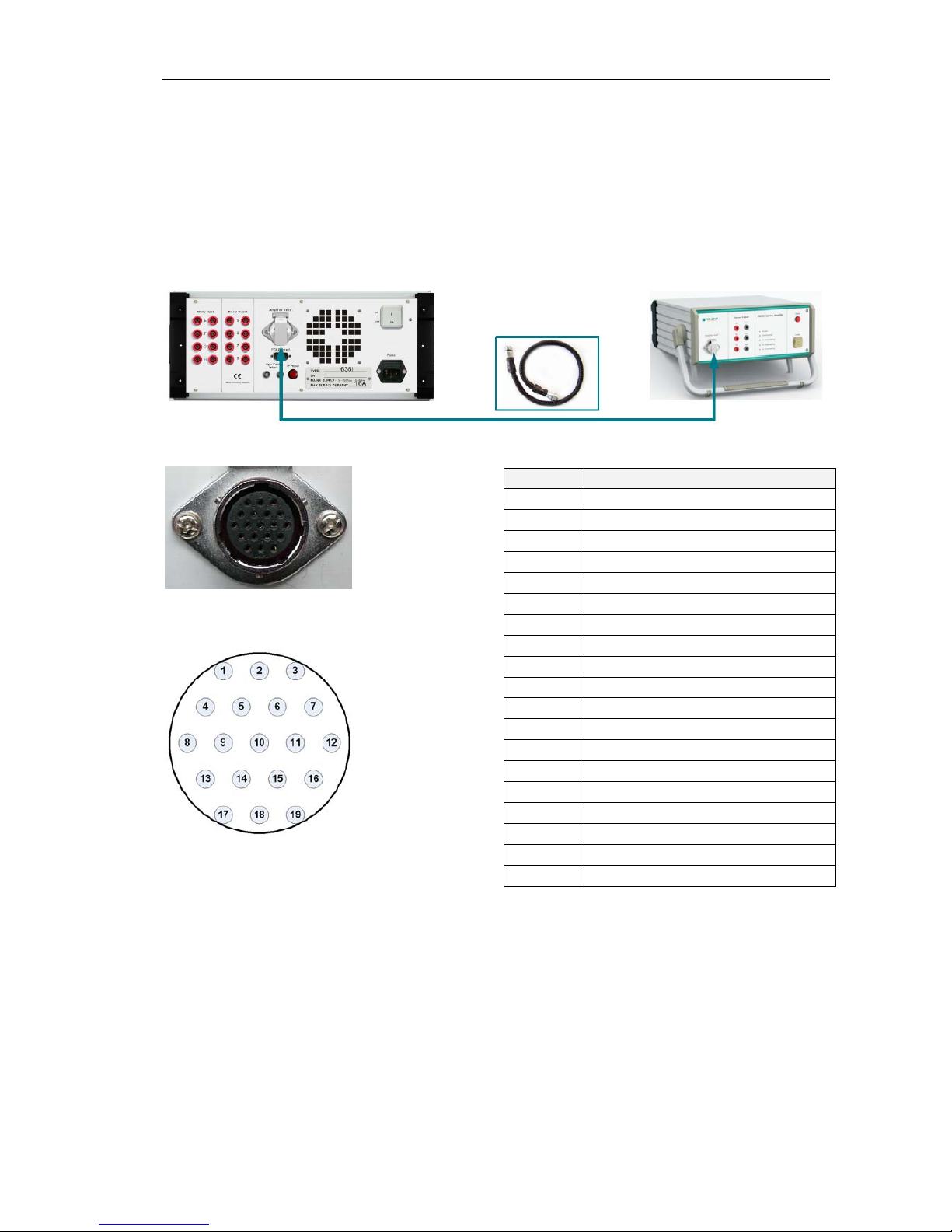
Current booster interface
This interface is used to connect to the external current booster (optional) for testing high burden
relays.
Please refer to “Current booster user manual”
for details
Pin Signal
1 Current IA
2 Current IN
3 Current IB
4 Current IN
5 Current IC
6 Current IN
7 Current Ia
8 Current In
9 Current Ib
10 Current In
11 Current Ic
12 Current In
13 Voltage VA (not used)
14 Voltage VB (not used)
15 Voltage VC (not used)
16 Voltage VZ (not used)
17 Voltage VN (not used)
18 Not used
19 Not used
20
+12V(100mA)
21 +12V GND
22 Range switcher 1
23 Range switcher 2
24 Range switcher 3
25 Range switcher 4
26 Range switcher (GND)
PW636i Hardware Instruction Manual
10
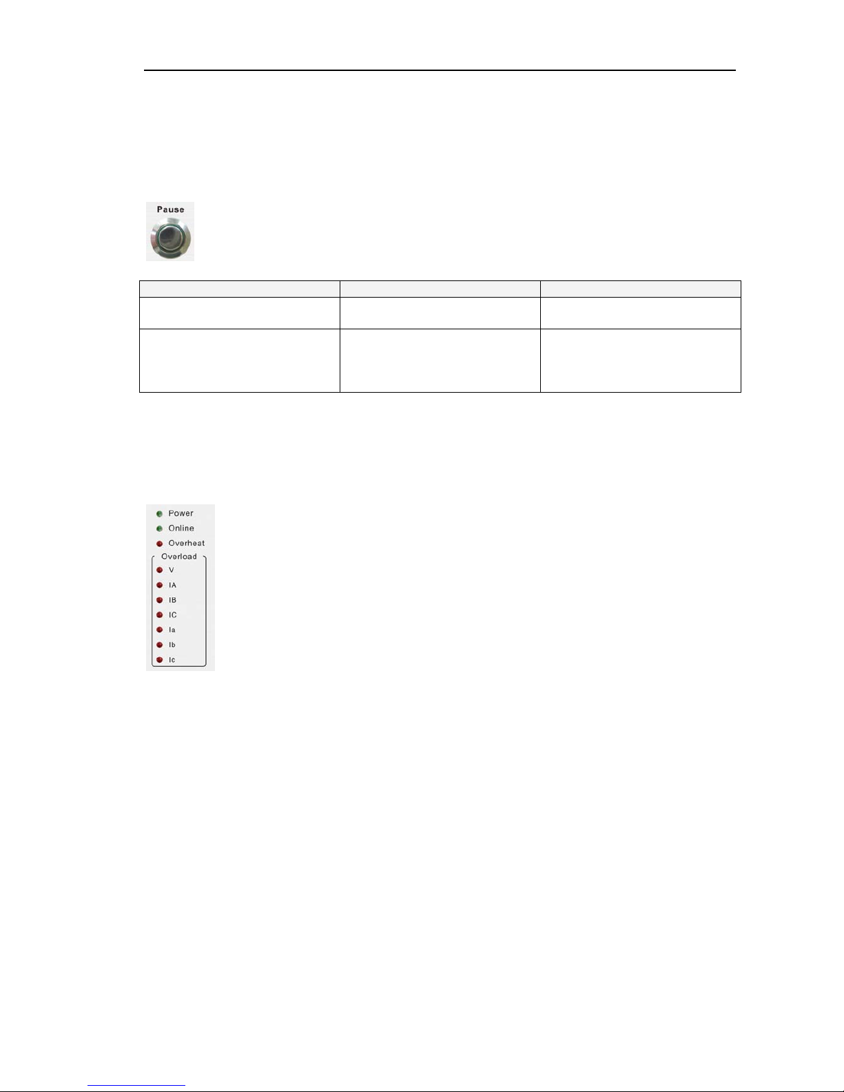
Pause button
The Pause button on the front panel is designed to cut the current/voltage outputs either for test
purpose or under emergency case.
‘Manual’ control mode ‘Auto’ control mode
Push ‘Pause’ button cut the current/voltage cut the current/voltage, PC
software will continue to run
Release ‘Pause’ button current/voltage output will be
recovered from the point
where we push the Pause
button
current/voltage output will be
recovered from the software
execution point at the moment
we release the Pause button
LED Indication
The LED indication on the front panel gives information about the hardware working conditions
In normal working condition the status of LEDs will have the following indication in ‘Power on’ and
‘Testing process’ conditions
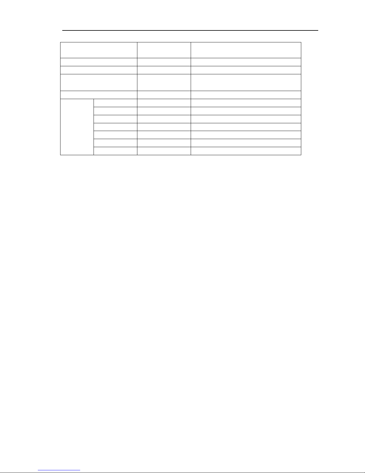
PW636i Hardware Instruction Manual
11
Power on
condition
All current/voltage channels are
having outputs
Power lamp Lighted Lighted
Online lamp
Not lighted Lighted and flashing
PAUSE lamp Not lighted
(push to light)
Not lighted(push to light)
Overheat lamp Not lighted Not lighted
Overload
lamp
V Not lighted Not lighted
IA Not lighted Not lighted
IB Not lighted Not lighted
IC Not lighted Not lighted
Ia Not lighted Not lighted
Ib Not lighted Not lighted
Ic Not lighted Not lighted
PW636i Hardware Instruction Manual
12
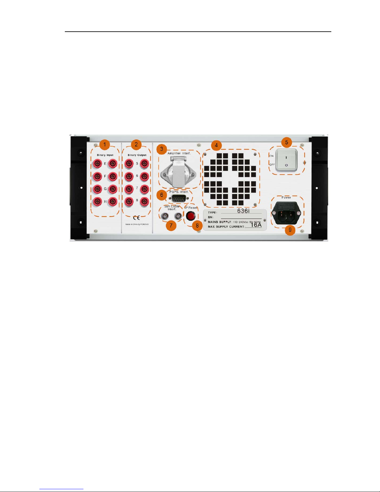
Rear panel
1. Binary input group 2
2. Binary output group 2
3. External amplifier and low level output
interface
4. Ventilation
5. Power switcher
6. GPS interface
7. Multi-kits synchronization interface
8. IP reset
9. Connector for mains supply
PW636i Hardware Instruction Manual
13
External amplifier and low lever output
interface
This interface is used to connect to external amplifier (optional) to increase the output channel and
output power.
The 12 low level outputs are to be used for testing relays with Rogowski or voltage dividers input.
For more information about the external amplifier please refer to “External amplifier user
manual”
Pin Signal
1 Low level output 1
2 Low level output 2
3 Low level output 3
4 Low level output 4
5 Low level output 5
6 Low level output 6
7 Low level output 7
8 Low level output 8
9 Low level output 9
10 Low level output 10
11 Low level output 11
12 Low level output 12
13 Low level output GND
14 Control signal
15 High speed counter 1
16 High speed counter 2
17 High speed counter 3
18 High speed counter 4
19 High speed counter GND
PW636i Hardware Instruction Manual
14
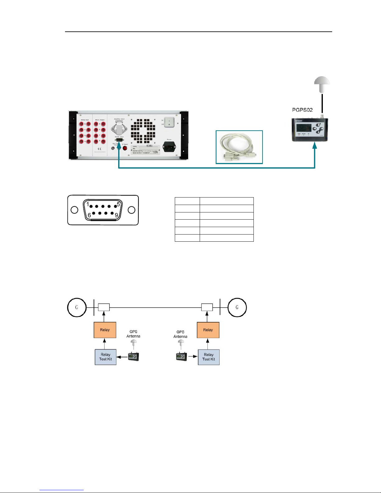
GPS interface
This interface is used to connect to our optional PGPS02 GPS-based synchronization device.
DB9 Chassis contact, male
----------------------------------------------
Note:
PPS means Pulse Per Second
----------------------------------------------
One popular application of GPS-synchronized control is for end-to-end test for line protection relay
Please refer to ‘PGPS02 user manual’ for details
Signal Contact pin
Power 1
Ready 2
PPS 3
GND 5
GND 9
 Loading...