

Ponovo PCT200 Series, PCT200i, PCT200Ai User Manual

PCT200 Series CT/PT Test System User Manual
1
PONOVO POWER CO., LTD
No. 139 Jinghai Third Road, BDA, B ei j ing, China, 100176
Office
TEL. +86 (10) 59089666
E-Mail Info@relaytest.com
Website www.relaytest.com / www.ponovo.com.cn
PCT200 Series User Manual
VERSION: PCT200 -AE-1.04
DATE: JUNE 2017
This manual is the publication of PONOVO POWER CO., L TD. Any form of copy should obtain the
consent of it.
This manual represents the technical status for the moment of publishing. The product information,
description and specifications mentioned in the manual do not have any contact binding force and
PONOVO POWER CO., LTD remains the right to make modifications to the technical
specifications and configurations without prior notice. PONOVO POWER PONOVO explicitly
exonerates itself from all liability for mistakes in this manual

PCT200 Series CT/PT Test System User Manual
2
Notes:
In order to prevent static electricity, the PCT and test CT must be connected t o
ground safely before test.
Avoid electric shock accident when the output voltage is above 36V.
Short circuit is prohibited at output side while testing.
Connect wires in accordance with instructi ons.
External voltages and currents are prohibited to apply on the tester ’s output.
Avoid the equipment being wet by rain.
Contact manufacturer timely and do not repair it when device works abnormally.

PCT200 Series CT/PT Test System User Manual
3
Special Tips:
1. CT/PT testing system (called PCT) is applied in the electromagnetic and low leakage flux
current transformer (CT without gapped core or compensation) and inductive voltage
transformer (PT) of power system. It completes the following test items:
CT load impedance
CT secondary coil resistance (Rct)
CT excitation characteristic
CT ratio
CT polarity
PT ratio and polarity
PT excitation characteristic
……
PCT is only used in the above fields and the wiring connection/ operat ions should be e xecuted in
the guide of the user manual. Any other usage is invalid. The users must operate PCT in the
proper way. Otherwise, imprope r operation might cause damage. The manuf acturer will not take
any responsibility for such damages. The users assume all respons i bilities and risks.
2. The power supply must be accordance with the requirements described in user manual.
3. Users can’t maintain the PCT without manufacturer’s authorization. Otherwise the warranty
period statement is invalid.
4. Users can’t disassemble the PCT without manufacturer’s authorization. Otherwise the
warranty period is invalid.

PCT200 Series CT/PT Test System User Manual
4
5. It is prohibited to maintain reform, extend or change the system or any other accessories.
6. Only original accessories are accepted i n test and detection process.
7. Do not switch-on and operate PCT in the place having explosive gas or water vapor
8. Avoid the equipment to be wet by rain
9. Do not block the ventilation outlets
10. Don’t s tand rightl y under the joint point in case of clamps hurting.
11. It is not allowed to connect or disconnect the test object in the operation process . The high
voltage caused by energy, storing in external induc tance, mi ght damage the hum an, P CT and
test object.
12. Make sure that the terminals of the test objects are not charging to exit the program.
13. Please make wiring connection in the guide of user manual whil e m aking CT test. If the wiring
is wrong, the high voltage might damage the CT or PCT.
14. Please make wiring connection in the guide of user manual while making PT ratio and polarity
test. If the users connect the PCT output with the secondary side of PT, thousands of volts
high voltage might be generated in the primary side and damage the PT or PCT.
15. Pleas e make wiring connection in the guide of us er manual while making PT excitation test.
The PCT output must be connected with the secondary side of PT. If it is connected with the
primary side of PT, it might damage the PT or PCT.
16. The t est of guess nameplate is only for reference.

PCT200 Series CT/PT Test System User Manual
5
Content
1. General Description .................................................................................................................... 7
1.1 Functions ........................................................................................................................... 7
1.2 Technical Specifications ..................................................................................................... 9
1.3 Features .......................................................................................................................... 10
1.4 Operation Preparation ..................................................................................................... 12
1.5 Block Diagram ................................................................................................................. 13
2. Panel Description ...................................................................................................................... 14
3. Operation Instruction ................................................................................................................ 15
3.1 Select Test Functions ....................................................................................................... 15
3.2 Set Test Parameters ........................................................................................................ 16
3.3 Control Output ................................................................................................................. 16
3.4 Save Test Report ............................................................................................................. 16
3.5 PCT Report Tools User Manual ....................................................................................... 19
4. Burden Test ............................................................................................................................... 31
4.1 Wiring Connection ........................................................................................................... 31
4.2 Test Operation ................................................................................................................. 32
5. CT Test ..................................................................................................................................... 33
5.1 Wiring Connection ........................................................................................................... 33
5.2 Test Operation ................................................................................................................. 35
5.2.1 Settings ................................................................................................................. 35
5.2.2 Rct Measuring ....................................................................................................... 39
5.2.3 Demagnetization .................................................................................................... 40
5.2.4 Polarity T est ........................................................................................................... 41
5.2.5 Excitation Test ....................................................................................................... 42
5.2.6 Ratio Test ............................................................................................................... 44
5.2.7 Auto Test ................................................................................................................ 45
5.3 Application Examples....................................................................................................... 46
5.3.1 Transmission line CT Test ...................................................................................... 46
5.3.2 CT Test in Y Voltage Transformer .......................................................................... 47
5.3.3 CT Test in the Star Connection Voltage Transformer ............................................. 48

PCT200 Series CT/PT Test System User Manual
6
5.3.4 Bushing CT Test ............................................................................................................... 49
5.3.5 Test CT with Tapping ........................................................................................................ 50
6. PT test ..................................................................................................................................................... 51
6.1 Wiring Connection ....................................................................................................................... 51
6.1.1 Polarity and Ratio Test ..................................................................................................... 51
6.1.2 Excitation Test ................................................................................................................... 53
6.2 Test Operation .............................................................................................................................. 54
6.2.1 Settings .............................................................................................................................. 54
6.2.2 Polarity and Ratio Test ..................................................................................................... 55
6.2.3 Excitation Test ................................................................................................................... 56
Appendix: Glossary .................................................................................................................................... 57

PCT200 Series CT/PT Test System User Manual
7
1. General Description
1.1 Functions
PCT200i PCT200Ai
CT
CT type P, TP, M P, TP, M(0.2S)
Ratio, polarity ◆ ◆
Coarse ratio ◆ ◆
Guess ratio ◆ ◆
Turn-ratio and error ◆ ◆
Ratio error and phase
displacement
◆ ◆
Rct ◆ ◆
Burden ◆ ◆
Excitation characteristic ◆ ◆
CT demagnetization ◆ ◆
Knee point (V-I) ◆ ◆
Remanence flux (Kr) ◆ ◆
Secondary time constant (Ts) ◆ ◆
Unsaturated inductance (Lm) ◆ ◆
Saturated inductance (Ls) ◆ ◆
Instrument security factor (FS) ◆ ◆
Accuracy limit factor (ALF) ◆ ◆
Composite error (εc) ◆ ◆
Eal ◆ ◆
Transient dimensioning factor (Ktd) ◆ ◆

PCT200 Series CT/PT Test System User Manual
8
Notes: The symbol “
◆” indicates it has the function.
The symbol “△” indicates assessment not to guarantee the accuracy.
The symbol “/” indicates i t doesn’t have the function.
Symmetrical short-circuit current
ratio (Kssc)
◆
◆
Peak instantaneous (total) error εˆ ◆ ◆
Guess nameplate
△ △
Report tools ◆ ◆
PT
Ratio
△ △
Polarity ◆ ◆
Excitation characteristic
△ △

PCT200 Series CT/PT Test System User Manual
9
1.2 Technical Specifications
Items PCT200i PCT200Ai
Output voltage range 0-120V
Output current range 0-5Arms (15A peak)
Output power 0.0001-500VArms (1500VA peak)
100% Ipn and 100% VA
Ratio test range 30,000:1-45,000:5
Ratio test accuracy﹡
1-2,000 0.05% Typ. 0.10%Gur
2,000-5,000, 0.08%Typ. 0.15%Gur
5,000-30,000, 0.10%Typ. 0.20%Gur
1-2,000 0.02% Typ. 0.05%Gur
2,000-5,000,0.03%Typ 0.10% Gur
5,000-30,000, 0.05%Typ. 0.20%Gur
Max. knee point voltage 45,000V
Burden test accuracy ±0.05% ±1mΩ Typ. ±0.1% ±1mΩ Gur. at 0.05-200Ω, resolution 0.1mΩ
Rct accuracy, resolution ±0.05%±1mΩ Typ. ±0.1%±1mΩ Gur. at 0.05-200Ω, resolution 0.1mΩ
Phase displacement﹡
1min Typ. 3min Gur.
resolution 0.01min
1min Typ. 2min Gur.
resolution 0.01min
Main supply
220Vac +20%~-15%/50-60Hz(Nominal)
90-260Vac/45-65Hz (Permissible)
Input power: max 2,000VA
Operation temperature
-10℃~50℃
Relative humidity ≤90%, non-condensing
Dimensions 470x200x245mm (WxHxL)
Weight 10kg/14kg
LCD display 8.4 inch, color display
Operating system Windows
Note: T he correspondi ng temperatur e of each parameter is 23℃±5℃. It is suggeste d the preheat tim e is longer
than 15 minutes.
The parameters are ensured accurately within one year.
The symbol “﹡” indicates the knee voltage is m ore than 3V.

PCT200 Series CT/PT Test System User Manual
10
1.3 Features
Apply the newest principle of m ulti point DC method and meet the standard of IEC 44-6
The voltage measurement of ratio and phase dis pl acement complies with standard of IEC
61869-2.
Measure ratio differential and angle differential accurately. The max ratio differential error is
±0.1%, max angle differential error ±3min and the ratio measure m ent range is 1~30,000.
Calibration certificate approved by National Center for High Voltage Measurement. The report
includes: angle differential, ratio differential test and stability test.
8.4 inch LCD with colorful graphic al interface for HMI.
The whole integration struct ure, anti-vibration and anti-electromagnetic interference
combination chassis.
Built-in computer for operation. All test items are completed automatically.
Light weight and small dimension due to small voltage and power output.
The voltage measurement is used to test the bushing CT and GIS CT that can’t be measured
by traditional way.
The knee point voltage of CT ranges from 1-45,000V. And the excitation characteristic test
speed is fast. These features surpass that of traditional analyzer.
Apply to various types of CT (including TP type) excitation, ratio, polarity, secondary winding
resistance, load, ratio differential and angle differential etc steady-state or transient
characteristic test.
Automatically test knee point vol tage/ c urrent, ALF, FS, Ts, and Kr etc CT parameters.
Users can select ten groups of excitation data to save.
It lists the ratio error and phase error table and changes the report data in condition the rated
current 1%-300% be set.
The PCT automatically memories test items, report items, and report setting items.
The report can be converted into EXCEL format locally. More than thousands of reports are
saved in it for checking and printing.
Users can export the test results by U disk as wel l as upgrade.
The report tool software is convenient for report saving, converting and analyzing which is for
data contrast, judgment and assessment.

PCT200 Series CT/PT Test System User Manual
11
User-defined test according to the defined standards.
PT test items: ratio, polarity and volt-a mpere characteristic.
PCT200 Series CT/PT Test System User Manual
12
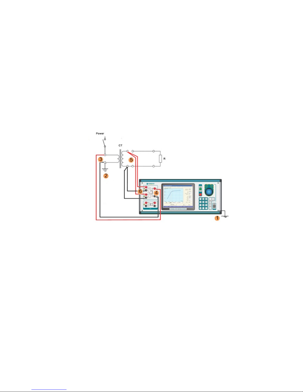
1.4 Operation Preparation
Preparation:
CT secondary side load loop disconnection and secondary wi nding off-grounded
CT primary side disconnects with busbar
Order of connection:
1. The chassis of PCT is grounded.
2. One end of CT primary side grounded (P2)
Note: There is a grounding switch in one side of primary. No matter the grounding switch is in P1
or P2, only one end is supposed to ground.
3. The test lead connects with P1, P2 of CT.
4. The other end of the lead connects with P1, P2 of PCT200i.
5. One secondary side connects with one group of CT’s S1 and S2
6. The other Secondary side connects with S1, S2 of PCT200i.
7. Power on

PCT200 Series CT/PT Test System User Manual
13
1.5 Block Diagram
PCT200 Series CT/PT Test System User Manual
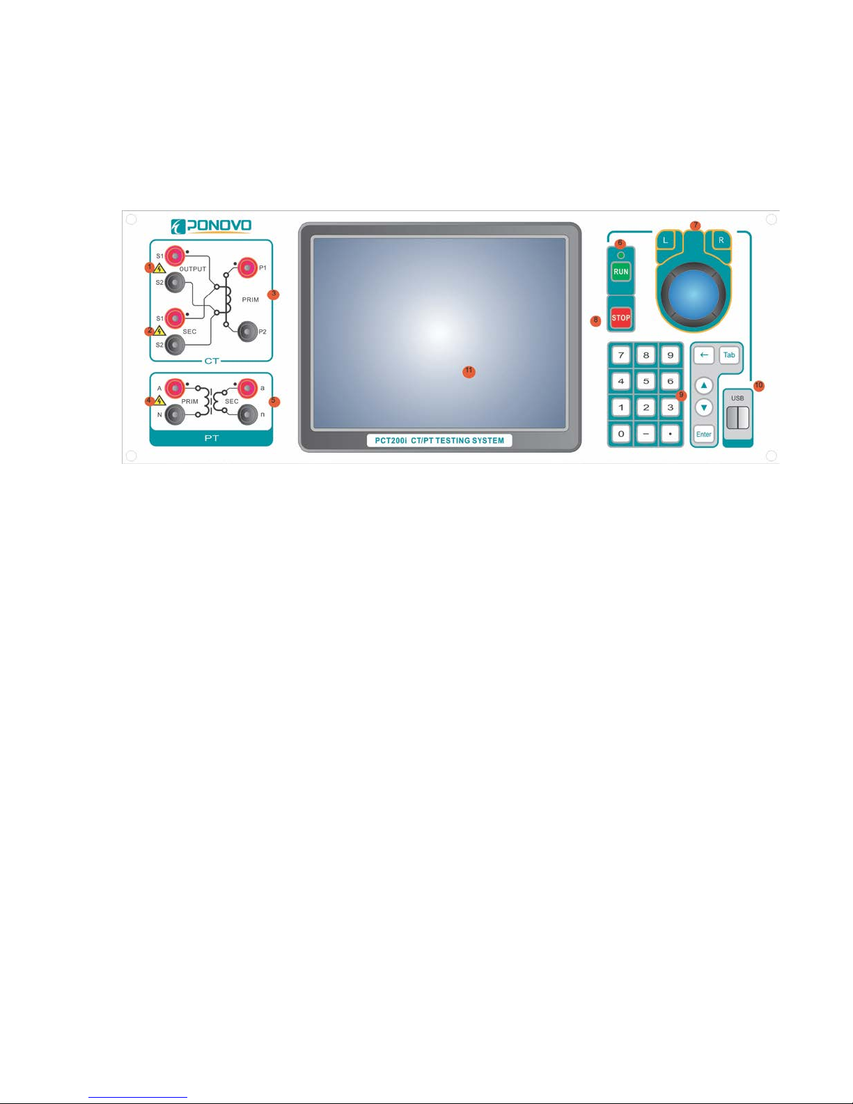
14
2. Panel Description
1) Connect i ng CT secondar y side
2) Secondary side voltage test while testing CT/PT (PT Excitation only)
3) Primary s ide voltage test while testing CT
4) Connect i ng PT primary side
5) Secondary side voltage test while testing PT
6) Run lamp: output indicator--flashing while outputting
7) Rotary encoder: sel ecting menu and setting specifications
8) Run and stop buttons
9) Keyboard
10) USB interface
11) LCD display

PCT200 Series CT/PT Test System User Manual
15
3. Operation Instruction
3.1 Select Test Functions
Choosing main menu button at any interface to enter, then rotating rotary encoder to change the
cursor position and select specified testing but ton. The selected operation is displayed in the
below.

PCT200 Series CT/PT Test System User Manual
16
3.2 Set Test Parameters
Set variable parameters by pushing keyboard and press ing mouse.
3.3 Control Output
The run and stop buttons on the panel or the start test and stop test functions c an control the
output. While output, the operation indicator will flash.
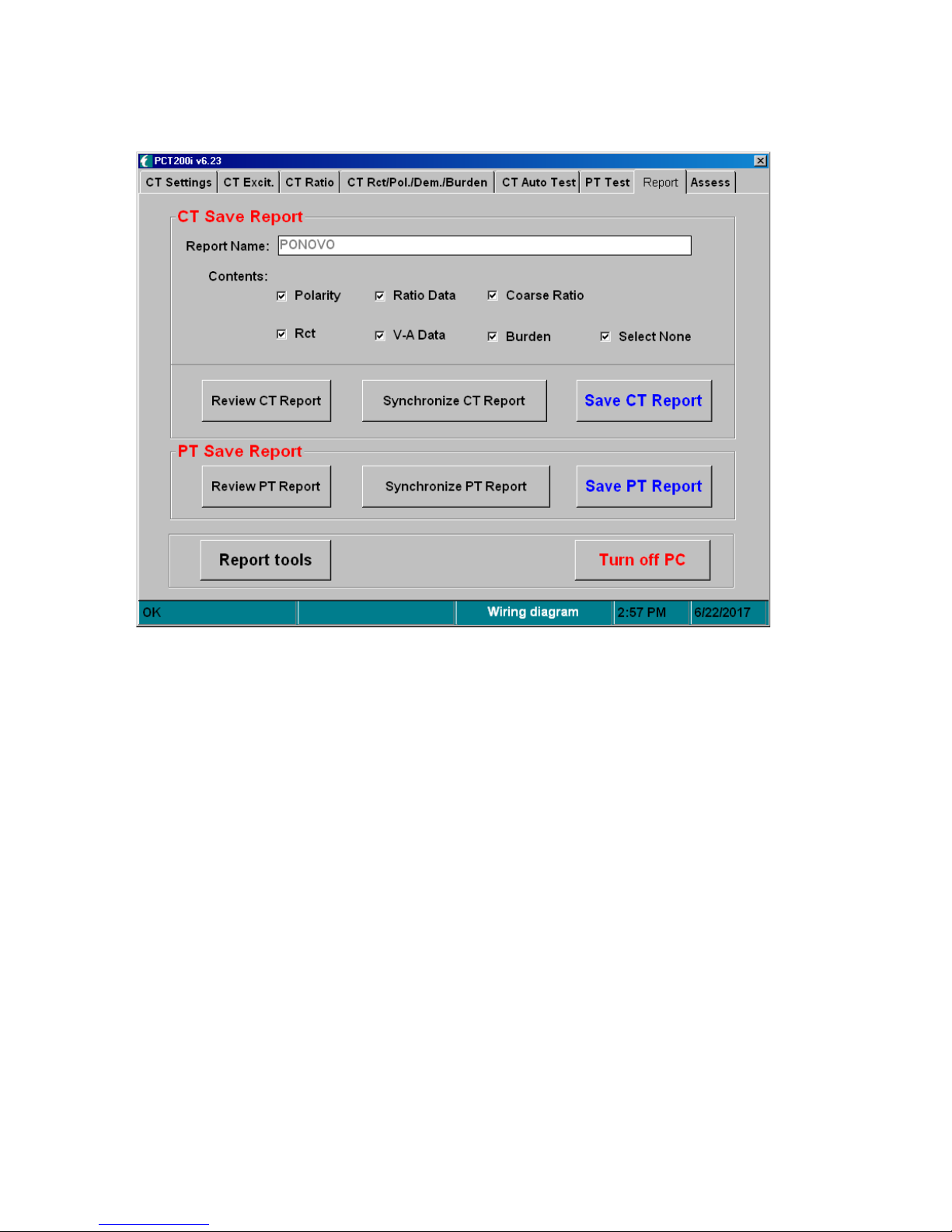
3.4 Save Test Report
After testing, select the report menu and enter into report save interface. The report name is put in
by keyboard and the content is selected by mouse s election. The report is saved autom atic ally in
the CT report file. The report can be copied and converted into EXCEL format in PC by U disk.
PCT200 Series CT/PT Test System User Manual
17
Synchronize CT Report: Synchronize today’s or all the reports into mobile disc showing below.
Save CT Report: Save the reports to Disc D.
Synchronize PT Report: Synchronize today’s or all the reports into mobile disc showing below.
Save PT Report: Save the reports to Disc D.
Report tools: For the operation of the Report tools, please refer to next chapter 3.5 PCT Report
Tools User Manual.
Turn off PC: It is suggesting exiting the operation system, then switc h off the power supply after
reminder.
PCT200 Series CT/PT Test System User Manual
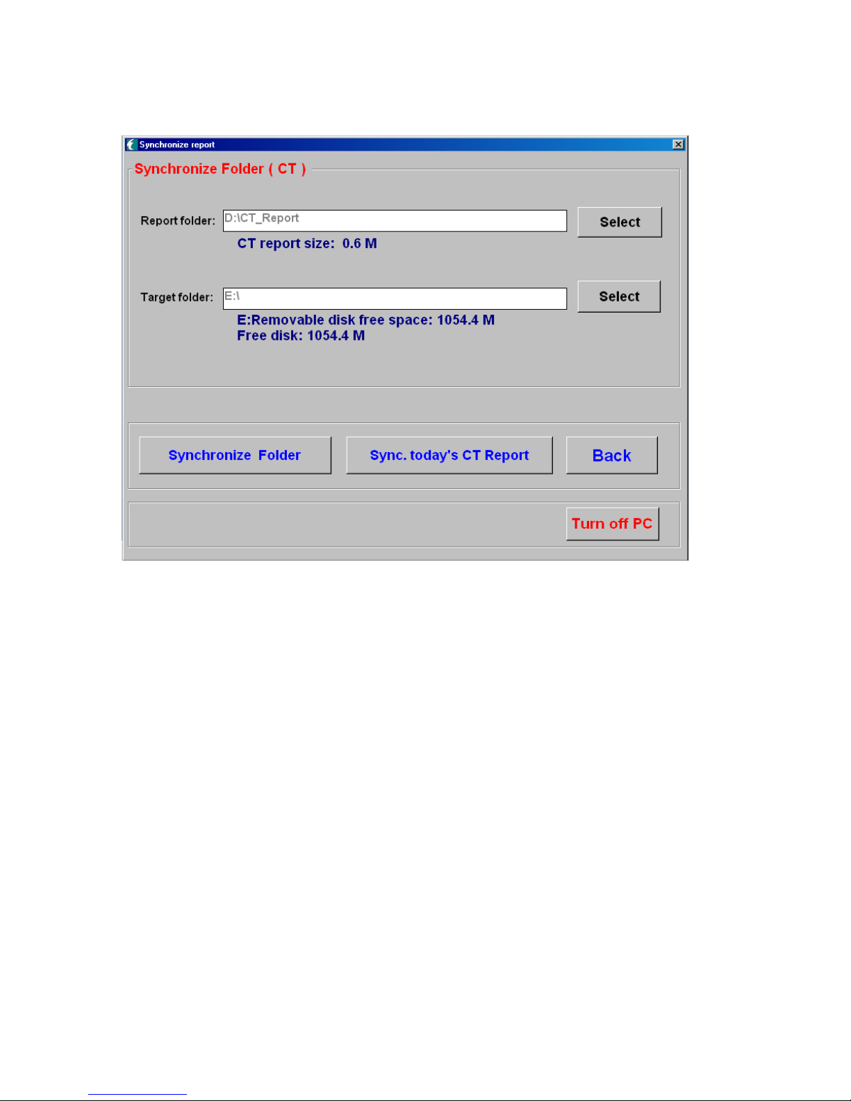
18
1. Report folder: Select the report folder to be synchronized.
2. Target folder: Select the folder to save the synchronized reports.
3. Synchronize Folder: Synchronize all the reports in the folder.
4. Sync today’s CT/PT report: Synchronize the day’s CT/PT reports.
5. Back: Back to the test interface
6. Turn off PC: Exit the system and s wi tch off the power supply.
PCT200 Series CT/PT Test System User Manual
19
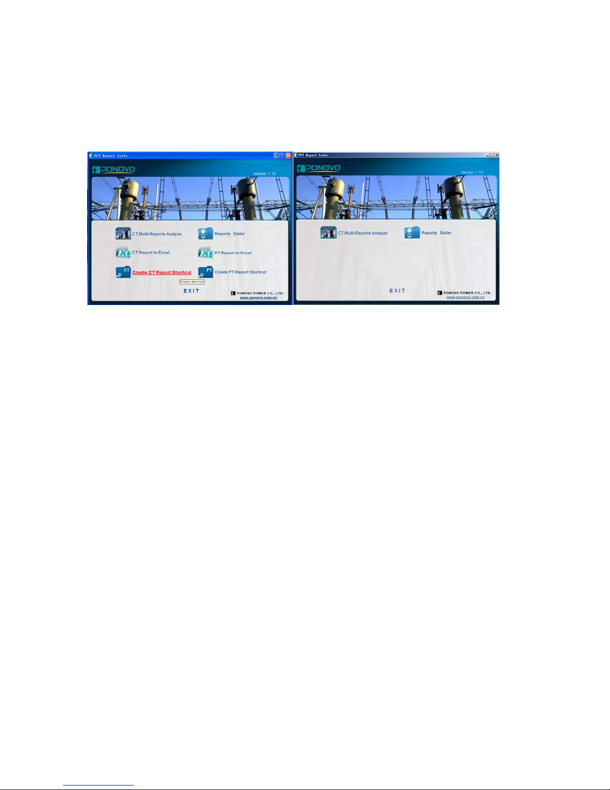
3.5 PCT Report Tools User Manual
Figure 1 Figure 2
In figure 1, it is the PC software interface installed Excel.
In figure 2, it is the PC software interface without Excel or in the PCT system.
1. CT multi-report analyze: to analyze the CT multi-report and c urve.
2. Report folder: t o generate the reports including Excel and JPG form ats. In the PCT system,
the report is .pct format. All the reports are saved in Disc D.
3. CT report to excel: to convert the CT report into Excel format report, support multi-report
selection. The conversion process includes the tips ( conversion completion and the number
of conversion files)
4. PT report to excel: to convert the PT report into Excel format report, support multi-report
selection. The conversion process includes the tips (conversion completion and the number of
conversion files)
5. create ct excel report shortcut: to create the desktop file of CT report
6. create pt excel report shortcut: to create the desktop file of PT report
 Loading...