

Page 1
User Manual
Model No: TC-15A
Thank you for purchasing the Temperature Controller by Poniie. Please read
this manual carefully before using this product.
Page 2

1. Safety Precautions
1.1 Ensure the product is used withi n t he spec ification (Max. 15A).
1.2 Do not disma ntle the devi ce wit hout authori z ation to avoid
unexpected accident.
1.3 Do not operate the controller near any high temperature, high
humidity, explosive or inflammable field.
1.4 Children are not allowed to op erat e the devi ce. Keep children
away from the controller.
1.5 Do not use in s al t wate r or corrosive water, the m etal N T C probe
will be slowly damaged by salt water or acid-alkali water.
1.6 NOTE: If the relays are used over capability, contact fusing or
burning may occur . Ple ase use the rel ays wit hin th ei r rated load.
2. Overview
What is TC-15A?
TC-15A is an easy-to-use, safe and reliable dual relay output
temperature controller. It can be connected to both hea t ing and cooli ng
loads at the same time to control temperature.
This unit can be used as over temperature protection or automatic
temperature control system for various tasks. Such as Sous-vide,
Terrarium Heat Control, Heat Mats, Germination, Fermentation and
Brewing.
Page 3
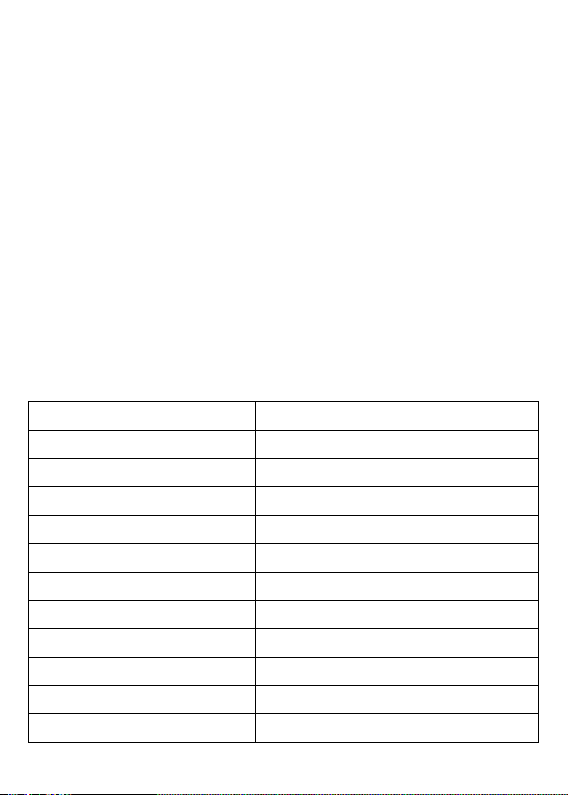
Main features
Temperature Control Range
-40.0 ~ 99.9℃
Temperature Resolution
0.1℃
Temperature Accura cy
±1.0 ℃ (-20.0 ~ 70.0 ℃)
Input Power
100~125V, 50/60Hz
Maximum Output Load
15A, 100 ~ 125V (1650W @110V)
Buzzer Alarm
Low and High Temper atur e Alarm
Sensor Type
NTC sensor
Contr ol Pa n el Cable Length
1.5m / 4.9ft
Input Power Cable Length
1.7m / 5.6ft
Sensor Length
2.0m / 6.6ft
Ambient Temperature
-20.0 ~ 55.0 ℃
Ambient Humidity
20~85% (No Condensate)
• Pre-wired plug and play;
• Dual relay output for heating a nd cooling;
• Support reading with ℃ and ℉;
• Dual displ ay windows, be able to display measured temperature
and set center t e mpe ra tu re at the same time ;
• Auto saving function with power-off memory;
• Calibration function;
• Compressor delay protection;
• High and low temperature alarm;
• Faulty sensor alarm
3. Specification
Page 4

4. Key Operation Instruction
The upper window, in worki ng mode, displays curre nt environment
tem perat ure and working status; i n s etting mode, displ ays men u c ode.
ON: Refri geration is in working sta t e;
FLASHING: Refrigeration is in compressor delay time.
ON: Heating is in working state;
OFF: Not work ing.
The lower window, in working mode, displays shutdown
temperature point (TS) for bot h h ea ti n g an d cool i ng (It ca n be tak e n
as the centr al tem per atu re po int); in se tting mode, disp lays setting valu e
of menu codes.
When controller working normally, press
Temperature (TL) point is displayed; press
Tempera ture (TH ) point is displa yed. T he scree n will aut o return t o
normal display after 2 seconds.
“▼ ” k ey, t he setting Low
“▲” key, th e setting Hi gh
4.2 How to set parameters?
Bas ic Set ti n g M ode : Press “SET” key to enter the basic setting mode,
You onl y nee d to set thr ee te mper at ure p oint s TL, TS a nd TH t o set a
suitable control range. TL/TS/TH relationship is as follows:
Page 5

After setting, hold down the “SET” button 3 seconds or leave it with no
Cooling
Heating
TL
TS
TH
operation 15 seconds, the syste m will save the paramete r changes and
ret urn to t he working mode.
Note: You can only set the basic Settings, leaving the advanced
Settings unchang ed, and only change the adv anc ed Settings pa rameters
if necessary.
Advanced Setting Mode: Pr e s s & h ol d dow n
ente r t he ad van ced set tin g mod e. You are a ble t o s et AL (Low Alar m
Temperature point), AH (High Alarm Temperature point), PT
(Compressor Protection Time), CF (℃/℉ Display setting) and CA
(Calibration function) parameters. After settings, press & hold down
“SET” key 3 seconds or lea ve it wi th n o ope rati on 1 5 secon ds to sa ve
parameter changes and return to working mode.
User Tips: 1)Under set ting mod e, press
parameter codes, press
2)Press & hold down
“▼”& “▲” to adjust the setting values below.
“▼” & “▲” can adjust setting value more quickly.
“SET” key 3 seconds to
“SET” ke y t o cycle through all
Page 6
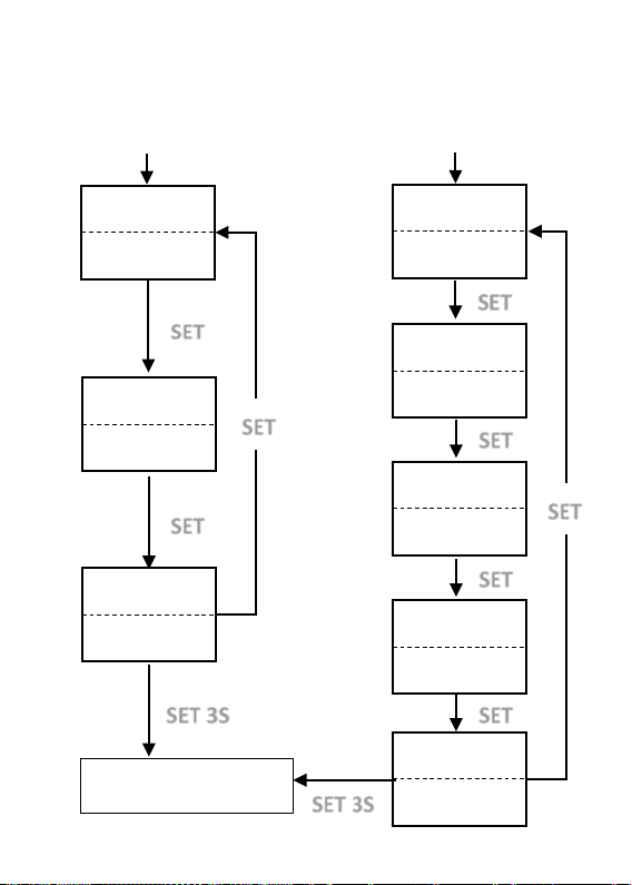
5. Setup Flow Chart
Basic Setting Mode
SET 3S
SET 3S
TL
SET
23.0℃
SET
AL
-20.0℃
SET
AH
90.0℃
SET
PT
2min
CF ℃ CA
0℃
TS
25.0℃
TH
27.0℃
SET
SET
Working Normally
SET
SET
Short press “SET”
Advanced Setting Mode
Press & hold “SET” for 3s
Page 7
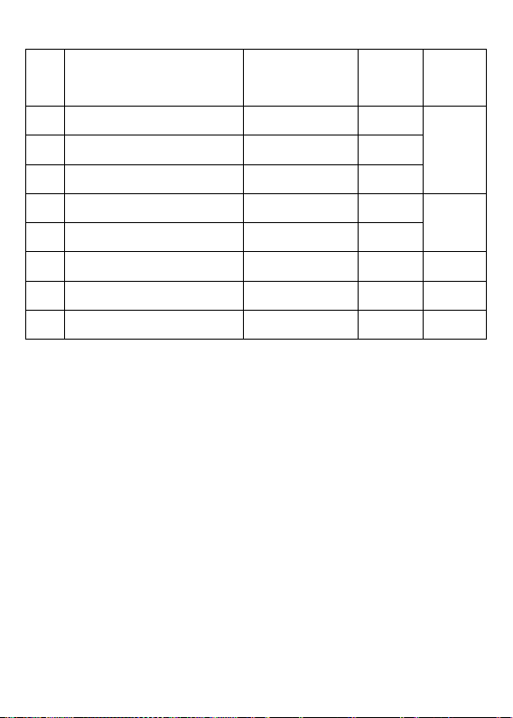
6. Menu Instruction
Menu
C
Function
Setting
R
D
Setting
Remarks
TL
Low
-
23.0℃
6.1
TS
Shutdown
25.0℃
T
High
-
27.0℃
AL
Low Alarm
-
6.2
AH
High
(TH+0.5)
PT
Compressor Delay
0~1
2min
6.3 CF
℃/℉ Display
℃/℉ ℃
6.4 CA
Temperature Calibration
-
0
6.5
ange
40.0~99.9℃
40.0~99.9℃
20.0~(TL-0.5)℃ -30.0℃
~80.0℃ 90.0℃
0min
20.0~20.0℃
ode
H
Temperature Po i nt
Temper ature Point
Alarm Temperature
Temperature Point -40.0~99.9℃
Temperature
6.1 Temperature Control Range Setting (TL, TS, TH)
This controller has a heating and cooli ng control ou tlets. Howe ver,
you can only use the heating or cool ing side for your proje ct .
When measured temperature ≤ TL, sy ste m ente r h e ating state, the
heating outlet relay starts to work; when it he ats up to shutdown poin t
(TS), the heating relay stops.
When measured temperature ≥ TH, system ent er cooling st ate, the
cooling outlet rela y s tarts to work; when it cools to shutdown point
(TS ) , the cool ing r elay stops.
In case the time interval between two cooling action is less than PT,
pleas e re fer to 6.3.
efault
℃
Page 8

Caution: Please be aware of the temperature surge risk when setting a
large temperature gap b etween TL--TS /TS--TH. Recommend to set
the gap smaller than 10 degrees. The tigh ter gap the mor e stabl e real
temperature.
Note: Please che ck and test your setting every time before leaving
controller to a long-term running.
6.2 Temperature Alarm Setting (AL, AH)
When measured temperature ≤ AL, low t emperature alarm will b e
triggered, buzzer will alarm until temperature>AL or a ny k ey is
pressed.
When measured temperature ≥ AH, high temperature alarm will be
triggered, buzzer will alarm until temperature<AH or any key is
pressed.
Note: If you set the AL ≥ TL, then the real low temperature alarm
point is T L-0.5℃. If you set the AH ≤ TH, the real high alarm point is
TH+0.5℃.
6.3 Compressor Prot ection T ime (PT)
Under cooling mode, compressor protection will keep the refrigeration
off b etween cycle s to pr otect your comp ressor. T hat means
compressor won't start refri ge ra tion immediate ly, but waiting for a
delay time if it falls into the PT time frame. Delay time will be
Page 9

calc u la ted right af ter the momen t refrigeration stops .
6.4 Display in Celsius or Fahrenheit degree (CF)
Users can select display in Celsius or Fahrenheit degree unit according
to their need s. Default setting is ℃.
Note: when you select Fahrenheit unit, the display for over 100℉ will
be a w hole num ber, resolution becomes 1℉.
6.5 Temperature Calibrat ion (CA)
When there is a deviation between measured temperature and actual
temperature, you can use the calibration function to align the
measured temperature an d actual t emperature. Th e corrected
temperature equa l s to temp erature before calibration plus correct ed
value (corrected valu e can be positive, 0 or negative value)
7. Error Description
1) If LED displays flashing code AL or AH, please kindly check your
AL or AH setting in advanced setting mode. Buzzer will alarm until
temperature fall into setting range or any key is pressed (the flash
indication will continue unless the temperature goes into normal range).
2) If LED displays code ER, then sensor is in short circuit or open loop.
Please contact Poniie customer service (support@poniie.com) for
solution.
 Loading...