

Pond Boss FP1250UV User Manual
Pressurized Filter
ITEM #FP1250UV
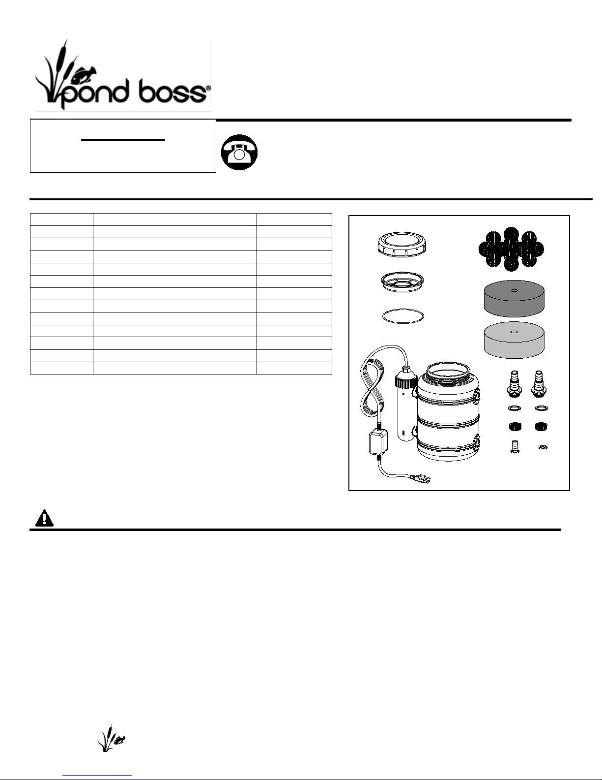
PACKAG E CONTENTS
WARNINGS AND CAUTIONS
Part
Description
Quantity
A
Tank with UV clarifier
1
B
O-ring
1
C
Cover
1
D
Lid
1 E Bio media balls
12
F
Coarse filter
1
G
Fine filter
1
H
Adapter
2
I
Gasket
2 J Locking ring
2
K
Small adapter
1 L Small gasket
1
REMINDER
BEFORE RETURNING TO STORE.
Questions, problems, m i ssing parts? Before returnin g
A
C
D B K
L
I
E F G
J
H
I J H
Up to 1250 gallons
CALL 1-888-755-6750
to your retailer, call our cust om er ser vice department at
1-888-755-6750, 8 a.m.-6 p.m., EST, Monday-Friday, or
email us at customercare@thepondboss.net. Or v isit our
website www.thepondb oss.net.
WARNING
• DO NOT SUBMERGE THE LIGHT ASSEMBLY.
• WARNING – Improper connection of the appliance-grounding conductor can result in a risk of elect ric
shock. Check with a qualified e lect r i cian or service representat iv e if you are in doubt whether the
appliance is properly grounded. Do not modify the plug provided with the appliance; if it w ill not f it t he
outlet, have a proper outlet inst al led by a qualified technician.
• If the appliance falls into w at er , DO NOT r each for it! First, unplug it and then retrieve it. If electrical
components of the applia nce get wet, unplug the appliance immediately.
• Do not operate any applianc e i f it has a damaged cord or plug, or i f it is ma lfunctioning or if it is
damaged in any manner.
• Always unplug the applian ce from the outlet before putt ing on or taking off parts, before cleaning or
when not in use.
• Connect only to a circuit that is protected by a ground-fault circu it-interrupter (GFCI).
• Risk of Electric Shock - Do not use the UV filter if the quartz tubing around the lamp is broken.
Immediately unplug and s eek an authorized repair service or discard the unit.
PLEASE CALL 1-888-755-6750 BEFORE RETURNING TO THE STORE.
WWW.THEPONDBOSS.NET
• GROUNDING INSTRUCTIONS – This appliance must be grounded. In t he event of a malfunction or
IMPORTA NT NOTES
PREPARATION
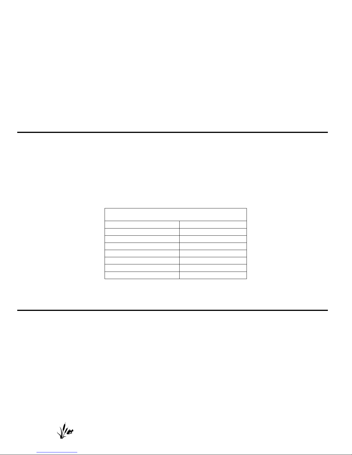
Lamp Voltage
60V
Lamp Current
0.2A
Lamp Power
9 W
Rated Frequency
60 Hz
UV Irradiance
35 µW/cm2
Bulb Life
8000 hours
Bulb Model Number
FUV9RB
UV Wave Length
UV(C) · 254 nm
breakdown, grounding wi ll r educe t he r isk of electric shock by prov iding a path of least resistance for
electric current. This appl i ance is equipped with a cord having a n appliance-grounding conductor and a
grounding plug. The plug mu st be plugged into an appropriate outlet that is installed and grounded in
accordance with all local codes and ordinances.
CAUTION
• UV light may cause irritati on t o the skin and/or eyes. Avoid exposure.
• DANGER – U L TRAVIOLET RADIATION – Dico nne ct Power Before Repla cing La mp.
• Prolonged or repeated exposure to UV light may have adverse physical effects including, severe
damage to your skin and eyes. Seek immediate medical att ention for overexposure to UV radiation.
• Keep the cord away from hig h t em per at ures or other heat sources.
• Do not lift the light or the transformer by its power cord.
• This light assembly has n ot been investigated for use in swi m ming pools or hot tubs.
• This product is designed t o pr ohi bit it s operation unless it is fully ass embled with the lamp base
screwed completely into the housing.
• UV rays are harmful to your eyes and skin.
• Do not attempt to operate this product unless the lamp is com pl et ely assembled within the light
housing.
• This product conforms to the C ode of Federal Regulations ( CF R) r equirements including, Titl e 21,
Chapter 1, Subchapter J, Rad iological Health.
Specifications
Before beginning assem bl y of product, make sure all parts are present. Compare part s w it h package
contents list and diagram above. If any part is missing or da ma ged, do not attempt to assemble, i nstall or
operate the product. Contact customer service for r eplacement parts.
• Estimated Assembly Ti me: 20 minutes
• Tools required for assembly: hacksaw.
PLEASE CALL 1-888-755-6750 BEFORE RETURNING TO THE STORE.
WWW.THEPONDBOSS.NET
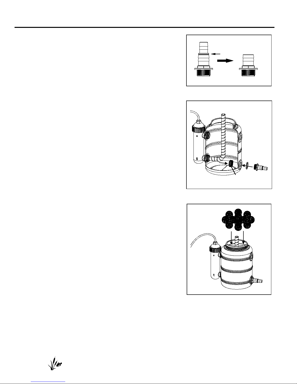
ASSEMBLY INSTRUCTIONS
A
J
I
H
Cut ring
1. If using 3/4 in. ID tubing, proceed to s t ep 2. If using 1 in. ID
tubing, cut the adapter as show n using a hacksaw. Fig. 1
Fig. 1
2. Assemble the locking ring, adapter and gasket.
Fig. 2
Fig. 2
3. Place the bio-balls inside the filter. Fig. 3
Fig. 3
PLEASE CALL 1-888-755-6750 BEFORE RETURNING TO THE STORE.
WWW.THEPONDBOSS.NET
 Loading...