

Pompetravaini TBAK Series, TBK Series, TBK 200, TBK 290, TBK 310 Disassembly And Assembly Instructions
...
(Rev. 2.0_10-2010)
DISASSEMBLY AND
ASSEMBLY INSTRUCTIONS
FOR MAGNETIC DRIVE
MULTISTAGE SELF-PRIMING
CENTRIFUGAL
PUMPS
TBK - TBAK
INTRODUCTION
f
These instructions are f or the m aintenance per sonnel f or m aintenance and/or r epair of the indic ated pum p s eries.
Disassembly and assembly procedures should be carried out by qualified personnel. Prior to working on the pumps the
maintenance person should be fully knowledgeable of the material outlined in this manual. Instructions relating to safety
of operation, installation and m aintenance will be f ound in the “ OPERATING MANUAL F OR CENT RIFUGAL PUMPS”
and in the “ DISASSEMBLY AND ASSEMBLY INST RUCTIONS F OR SELF -PRIMING MULT ISTAGE CENT RIFUGAL
PUMPS” which is usually supplied with the pump or it can be requested from your POMPETRAVAINI representative.
CAUTION!
Pumps series TBK and TBAK create a high magnetic field. Personnel should take proper precautions i
they are wearing pace-makers or if they are using instrumentation sensitive to magnetic fields.
The listed below minimum distances must be kept:
- When the magnetic rotor parts are disassembled:
users of pace-maker = 2 meters
floppy disk; magnetic cards, etc. = 1 meter
- When the magnetic rotor is mounted in the pump:
users of pace-maker = 1 meter
floppy disk; magnetic cards, etc. = 0,5 meter
Proper attire is necessary prior to beginning any work on the pum ps. Therefore, for your safety, always wear safety hat,
eyeglasses, gloves, shoes etc. and be sure to have proper tools necessary for the work to be done.
Do not f orce or s ubject pum p or any of its c omponents to s udden s hocks or violent im pact. Do not dam age w ith
markings or scratches the mechanical seal surface areas, the engagement surfaces and sealing areas. Do not damage
gaskets, and O-Rings. Do not leave in the pump foreign matter such as screws, nuts, bolts, washers, rags, etc.
When requesting spare parts or technical information for the pum p, always quote the pum p model number and s erial
number which is printed on the pump nameplate: therefore it is recommended not to remove the pump nameplate or, in
case this action will be necessary, write the serial number on the pump (for example on the flange).
Should additional inf ormation be r equired, pleas e do not hes itate to c ontact PO MPETRAVAINI or the closest
representative. Should there be any difficulties in repairing the pum p, it is recommended to send the pump for repair to
POMPETRAVAINI or the local authorised representative.
POMPETRAVAINI will not and c annot be r esponsible f or w ork done on the pum p by the c ustomer or non-authorised
personnel.
NOTE: Pump parts are identified by item numbers (VDMA). Item numbers can be found in the parts list under chapter
10 and cross-referenced with the sectional drawings under chapter 11.
All drawings given in these instructions are only schematics and not certified.
INDEX
1 - Actions to be taken prior pump disassembly
2 - “TBK” pump s eries dis assembly to r eplace
bushing
3 - “TBK” pump series bushing support assembly
4 - “TBK” and “ TBAK” pum p s eries s upport
disassembly
5 - Complete disassembly for pumps series “TBK”
The liquids and gas handled by the pum ps and als o their par ts c ould be potentially danger ous for
persons and envir onment: provide their eventual disposal in c onformity with the law s into f orce and a
proper environment management.
The present m anual is not as signed for pum ps subjected to the ATEX 94/9/CE directive. In case the
pump is assigned in environments subjected to the application ATEX 99/92/CE directive or in case the
pump is provided with a nam eplate indicating the AT EX stamp, it s trictly forbidden proceed to start up
the pumps but necessary to consult POMPETRAVAINI for clarifications.
For pumps subjected to the ATEX 94/9/CE directive it is available a dedicated integrative manual.
In preparing this manual, every possible effort has been made to help the customer and operat or with t he proper i nstallation and operation of the
pump. Should you find errors, misunderstandings or discrepancies please do not hesitate to bring them to our attention.
2
Disassembly and assembly instructions for magnetic drive multistage self-priming centrifugal pumps
6 - Complete disassembly for pumps series “TBAK”
7 - Internal m agnet r otor dis assembly f or “ TBK”
and “TBAK” pumps series
8 - Assembly of “TBK” and “TBAK” pumps series
9 - Spare parts
10 - Parts list
11 - Typical sectional drawings
1 – ACTION TO BE TAKEN PRIOR PUM P DISASSEMBLY
Prior starting disassembly activities it is required:
- Shut down the pump following usual shut down procedures.
- Disconnect electric motor from electric supply in order to make sure that it may accidentally start up.
- Close valves installed on pump suction and discharge.
- Wait and make sure that temperature is equal to ambient temperature prior to start any activity.
- Unlock the drain plug in order to drain completely the spiral casing.
Follow extra carefully this procedure in case pumped liquid is dangerous by contact or by inhalation.
At this regard it is mandatory to be provided with proper safety wear.
- Disassembly pipes and auxiliary connections in case connected to pump.
Remove coupling guard and, if present, spacer coupling.
- Loose the s upport foot VDMA 183 and, depending on needs , it is possible take away pump casing from piping and
baseplate and/or remove the electric motor.
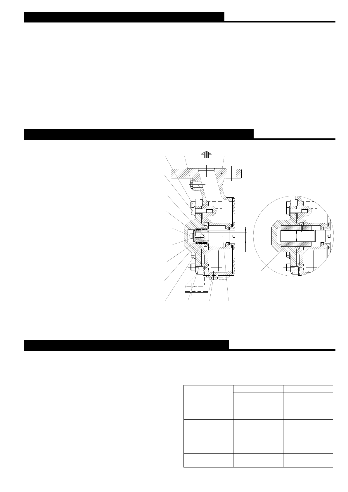
2 – “TBK” PUMP SERIES DISASSEMBLY TO REPLACE BUSHING
Loosen s crews VDMA 901 and ex tract the
bushing support VDMA 355 and its bushing
VDMA 310 or 310.3 ( in f unction if pum p
execution is /1 or /2) by means, if necessary,
of the s ame s crews as ex tractors in the
threaded holes available in the support self.
Later on, by m eans of a suitable extractor,
extract the bushing support (see fig. 1 or 2).
In case of execution /2 als o check the wear
of ceramic coated bushing VDMA 521 and if
necessary r eplace it loos ening the s crew
VDMA 914.5 and r emoving the washer
VDAM 554.
905
901
940.4
554
914.5
554.7
521
355
903
107
ØD
ØD
310
310.3
400.2
210.1903.1
F ig. 1 – Pumps series TBK/2 F ig. 2 – Pumps series TBK/1
3 – “TBK” PUMP SERIES BU SHING SUPPORT ASSEMBLY
Check wear of bushing VDMA 310 or 310.3 (in function of
execution /1 or /2) and, if nec essary, r eplace it w ith a
spare one: check the bushing internal diameter is the right
one for pump type indicated in obj ect (see fig. 1 or 2 and
tab. 1), then press it in the bushing support VDMA 355.
For execution /1 drill in the bus hing 3 radial holes Ø5 mm
at 120°, having c are that one hole is located in upper
position.
For ex ecution /2 dr ill in the bushing 1 crossing hole Ø3
mm loc ated in upper pos ition in c orrespondence of the
hole present in the bushing support VDMA 355.
After having loc ated the gas ket VDMA 400.2, assembly
the bus hing s upport on the dis charge casing VDMA 107
and tight the screws VDMA 901.
Disassembly and assembly instructions for magnetic drive multistage self-priming centrifugal pumps
Tab. 1 - Dimensions of bus hings ( VDMA 310 or 310.3)
internal diam eters alr eady pr essed in bushing
support VDMA 355 (see fig. 1 or 2)
Construction /2 Construction /1
PUMPS SERIES
TBK 200 --- --- 16 D7
TBK 290 ÷ 310 24 E8 22 D7
TBK 400 30 E8
TBK 500 --- --- 28 D7
TBK 650 30 E8
ØD
VDMA 310.3
+0,073
+0,040
+0,073
+0,040
ØD
VDMA 310
+0,068
+0,050
+0,086
+0,065
--- ---
+0,086
+0,065
--- ---
3
4 – “TBK” and “TBAK” PUMP SERIES SUPPORT DISASSEMBLY
(See fig. 5 and typical sectional drawings under chapter 11).
Remove stud nuts VDMA 902 and separate the s upport VDMA 330 f rom c asing c over VDAM 161 over coming the
magnets attraction force avoiding to damage the external rotor magnets VDMA 818.2.
To dis assembly the ex ternal m agnetic r otor w ith s mall s ize dr agging ( sealing c ontainer Ø 75, see fig. 6 and 10) is
necessary to remove the adaptor ring VDMA 502 loosening the grub screw VDMA 904.
Loosen screw VDMA 900.1 and remove the junk ring VDMA 550.1.
Extract then the fly wheel VDMA 132 with the external magnetic rotor VDMA 818.2.
Remove the half elastic coupling from pum p drive end and, unscrewing the s crews VDMA 914.4, r emove the ex ternal
bearing cover VDMA 360.1, the elastic ring VDMA 935 and circlip VDMA 932.1.
Loosen screws VDMA 900 and extract the internal bearing cover VDMA 360.2.
Apply now a strong pressure on the primary shaft VDMA 210 drive end to extract the bearing VDMA 320 and remove the
same shaft with bearing VDMA 320.1 from the support VDMA 330.
Remove circlip VDMA 932 and if necessary remove from shaft also bearing VDMA 320.1.
Verify that all parts are undamaged and w ear or tear scratches are not pr esent: if necessary replace those parts with
original spare parts before starting assembly, executing each step reverse to disassembly steps.
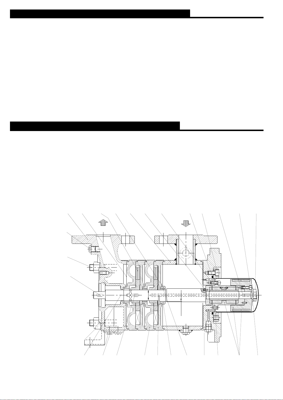
5 - COMPLETE DISASSEM BLY FOR PUMPS SERI ES “TBK”
Complete pump disassembly becomes necessary if, f or example, the pum p does not per form as expected due to an
excessive wear of impellers VDMA 230 and/or suction and discharge elements VDMA 109 and 114.
Replacing or machining the worn-out parts will be a question of economics and /or time available to complete the rapair.
This c hapter w ill c onsider the dis assembly of a pump without non-drive end s leeve bear ing hous ing and dr ive end
bearing and mechanical s eal hous ing ( see f ig. 3) : dis assembly and as sembly of thes e c omponents have been
addressed in chapters 2 – 3 – 4.
NOTE: where the mechanic is not familiar with the pump, it is advisable to draw a reference line along the pum p. Mark
each part with its location, rotation and assembly sequence; however the main components are already marked at
the ex ternal upper par t w ith reference logs to pr ovide the pr oper pos ition (see the attached “Disassembly and
assembly instructions for self-priming multistage centrifugal pumps”).
Disassembly work should be carried out w ith proper tools and using suitable disassembly sequence to pr event further
damage to the pump parts.
107 400.1 106 412914.1 914 914.2940.1
310.5230
920562.1
Fig. 3
Pumps series TBK
903
905
940.4
ØD1
310.2
ØD2
161210.1 903.1 940.2 114 109 310.1 562.2 818G
550
4
Disassembly and assembly instructions for magnetic drive multistage self-priming centrifugal pumps
 Loading...