

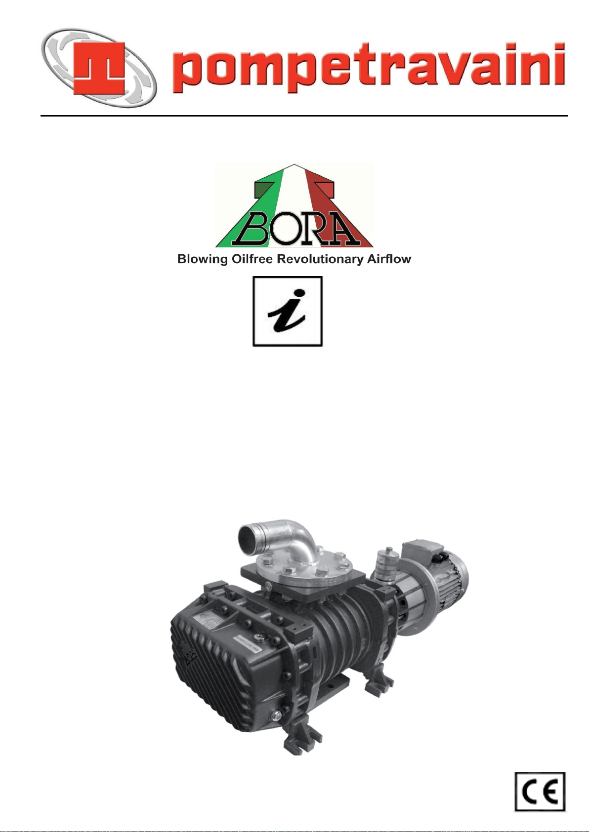
Pompetravaini BORA HV 233, BORA HV 73, BORA FP 583, BORA FP 363, BORA HV 353 Operating Manual
...Page 1
®
(Rev. 1.3_01-2018)
HIGH VACUUM PUMPS,
EXHAUSTERS AND BLOWERS
OPERATING MANUAL
Page 2

2
Thank you for purchasing a Pompetravaini-BORA product and congratulation on your choice.
This manual has been compiled to give you all the necessary information for the correct use of the products.
Please read it thoroughly, follow carefully the instructions and keep it intact.
This manual refers to vacuum pumps, blowers, exhausters, AC, HV and FP Series.
All pumps and systems are manufactured by:
POMPETRAVAINI S.p.A.
Via per Turbigo, 44 - Zona Industriale - 20022 CASTANO PRIMO - (Milano) – ITALIA
Tel. +39 0331 889000 - Fax. 0331 889090
www.pompetravaini.it
Divisione BORA, sede operativa:
Via della Scienza, 56 - 41122 MODENA – ITALY
Tel. +39 059 284210 - Fax +39 059 284042
WARRANTY: All products manufactured by Pompetravaini - BORA are guaranteed to meet the conditions listed on the
general terms and conditions of sale and/or conditions listed on the Order Confirmations.
Failure to strictly adhere to the instructions and recommendations listed in this manual will void the manufacturer’s
warranty.
Guarantee will be preserved only if the pump maintenance is carried out by Pompetravaini or an authorized service. Any
modification introduced to the pump without the authorization of Pompetravaini will lead to the loss of the guarantee.
If it is strictly necessary to dismantle the pump, please consult Disassembling Instructions on our
website "www.pompetravaini.it".
High vacuum pumps, exhausters and blowers operating manual
Page 3

3
INDEX
1
INTRODUCTION
7.2.3.1
REPLACEMENT OF THE 1ST SUPPLY OIL OF SEAL
1.1
GENERAL INFORMATION
SHAFT
1.2
MANUFACTURER’S INFORMATION
7.2.4
CLEANING THE FAN MOTOR PROTECTION
1.3
METHOD OF CONSULTATION
7.2.5
GENERAL EXTERNAL CLEANING OF PUMP
1.4
PERSONNEL QUALIFICATIONS
7.2.6
CHECK OF THE TRANSMISSION ELASTIC ELEMENT
1.5
PERSONAL PROTECTION EQUIPMENT
7.2.7
REPLACEMENT OF THE GEAR AND BEARING OIL
1.6
NAME PLATE
7.2.8
REPLACEMENT OF THE SHAFT SEAL OIL
2
SAFETY
7.2.9
FILTER MAINTENANCE
2.1
GENERAL WARNINGS
7.2.10
TRASMISSION
2.2
RESIDUAL RISK
7.3
PAINTING
2.3
PICTOGRAPHS
7.4
SPARE PARTS
2.4 IN CASE OF EMERGENCY
8
HOW TO RETURN THE PUMP
2.4.1
BASIC FIRST AID
9
DISMANTLING
3
DESCRIPTION
9.1
TROUBLESHOOTING BLOWERS
3.1
DESCRIPTION OF TYPES
9.2
TROUBLESHOOTING EXHAUSTERS
3.1.1
BLOWERS
9.3
TROUBLESHOOTING HV and FP SERIES
3.1.2
EXHAUSTERS AC
10
DIMENSIONS AND CHARACTERISTICS
3.1.3
HIGH VACUUM PUMPS, BOOSTER HV
and FP SERIES
3.2
INTENDED USE AND CONTRAINDICATIONS
3.2.1
INTENDED USE
3.2.2
CONTRAINDICATIONS
3.3
NOISE EMISSIONS
3.4
VIBRATIONS
4
INSTALLATION
4.1
RECEIPT AND CONTENT VERIFICATION
4.2
PACKAGING
4.3
TRANSPORT AND HANDLING
4.4
STORAGE
4.5
ENVIRONMENTAL CONDITIONS
4.6
PUMP INSTALLATION
4.7.1
MOTOR INSTALLATION ON BLOWERS AND
EXHAUSTERS
4.7.2
MOTOR INSTALLATION ON BOOSTER HV
and FP SERIES
4.8
USER SYSTEM
4.9
CONNECTION
4.9.1
INTAKE AND OUTLET CONNECTIONS
4.9.2
ELECTRICAL CONNECTION
5
ACCESSORIES
5.1
RV VACUUM RELIEF VALVE SETTING
5.2
SETTING OF THE OVER PRESSURE VALVE
5.3
AIR FILTER ON SUCTION
5.4 CHECK VALVE
5.5
SILENCERS
5.6
SOUNDPROOFING BOOTH
5.7
ANTISHOCK MOUNTS
5.7.1
ELASTIC HOSE
5.8
VACUUM AND PRESSURE GAUGES
5.9
CHOKED AIR FILTER GAUGE
5.10
MOTOR ELECTRICAL PROTECTION
5.11
ANTI ACCIDENT DRIVE COVER
6
INSTRUCTIONS FOR USE
6.1
OPERATION
6.2
START UP
6.3
STOP
6.4
DECOMMISSIONING AND PROLONGED
7
MAINTENANCE
7.1
GENERAL WARNINGS
7.2
OPERATIONS TABLE
7.2.1
CHECK OF THE LUBRICANT LEVELS
7.2.2
GEARS AND BEARINGS 1ST SUPPLY OIL
REPLACEMENT
High vacuum pumps, exhausters and blowers operating manual
Page 4
4
1 - INTRODUCTION
Pompetravaini S.p.A.
Via per Turbigo, 44 - Zona Industriale
20022 Castano Primo
(Milano - ITALY)
Tel. +39 0331 889000
Fax +39 0331 889057
www.pompetravaini.it
Divisione BORA
Sede operativa:
Via della Scienza, 56
41122 Modena, ITALY
Tel. +39 059 284210
Fax +39 059 284042
1.1 – GENERAL INFORMATION
This manual is a reference point to:
- the safety of use
- the installation and maintenance of pump or system.
- Start-up, laying-up and shutdown of pump or system.
N.B.: All the indications referred to the individual pump are effective also for systems that are using them, where not
explicitly specified.
This manual must be completed by the user taking note of the pump characteristics in the last page, it must be
preserved with care and it must be at qualified technician’s disposal.
This manual, originally written in ITALIAN, is an integral part of the pump and must be preserved with care for the life of
the pump itself. In the event of sale, lease or loaned use of the pump, it must be delivered to the new user along with
EC declaration of conformity. Carrying out any operations on the pump before reading and fully understanding all
instructions written in this manual is prohibited.
The pumps is designed for an industrial and continuous use by trained and authorized personnel, in
appropriate plants. It’s not allowed to use it in inappropriate plants or without appropriate protective
measures to prevent contact with children or untrained personnel.
The images contained in this manual are for an example purposes only and are not binding for the Supplier.
The Supplier reserves the right to modify components and/or parts in order to improve or for any other reason, without
updating this manual if operation and safety of the pump are not changed.
1.2 - SUPPLIER INFORMATION
Please always include the following information in all communications regarding the pump:
• pump model and serial number
• year of manufacture
• date of purchase
• detail information regarding problems verified
1.3 - METHOD OF CONSULTATION
For improved understanding of the information provided in this manual, warnings or instructions considered critical or
hazardous are marked with the following symbols:
DANGER
Failure to comply with these instructions may cause danger to persons.
WARNING
Failure to comply with these instructions may cause damage to the pump.
High vacuum pumps, exhausters and blowers operating manual
Page 5
5
1.4 - PERSONNEL QUALIFICATIONS
Fig. 1
To ensure that all operations performed on the pump are carried out safely, operators must have the qualifications and
requirements to carry out its operations. Operators are classified as follows:
FIRST LEVEL OPERATOR: Unqualified personnel, having no specific skills, able to perform simple tasks only.
MECHANICAL MAINTENANCE OPERATOR: Technician qualified to work on mechanical parts to carry out
any necessary adjustments, maintenance or repairs. Not qualified to work on electrical systems in the
presence of voltage.
ELECTRICAL MAINTENANCE OPERATOR: Technician in charge of all operations of an electrical nature. Can
operate in the presence of voltage inside cabinets and connector boxes
1.5 - PERSONAL PROTECTION EQUIPMENT
This manual assumes that the pump has been installed in workplaces, which comply with all mandatory safety
requirements; in particular, it is mandatory that personnel are equipped with personal protective equipment in relation to
the activities that must be performed.
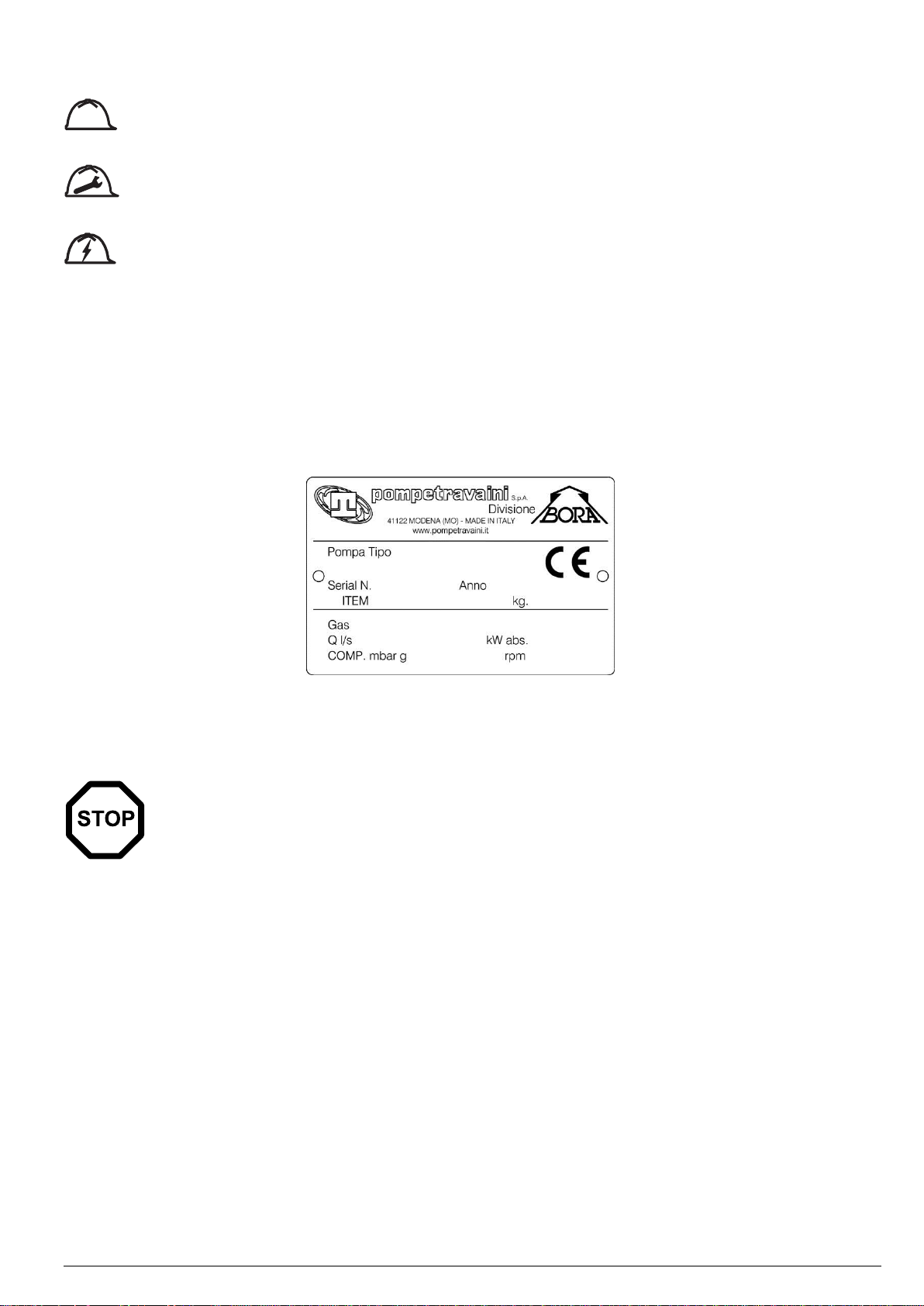
1.6 – NAME PLATE
The pump has an identification plate which shows the Supplier’s name, address, EC label, construction year and its
technical data.
WARNING
Removing or tampering with the identification plate is strictly forbidden.
High vacuum pumps, exhausters and blowers operating manual
Page 6
6
2 - SAFETY
2.1 - GENERAL WARNINGS
WARNING!
CAREFULLY READ FOLLOWING INSTRUCTIONS.
Strictly adhere to the instructions listed below to prevent personal injuries and/or equipment damage.
- ALWAYS apply the pump for the conditions outlined on the confirming order.
- Be ALWAYS informed on locations of first aid sites inside the company and carefully read safety and medical first aid
prescriptions in force.
- ALWAYS have a fire extinguisher in the vicinity of the pump installation.
- Any work on the pump must ALWAYS be carried out by at least 2 qualified people and expressly authorized.
- Electrical connections on the motor or accessories must ALWAYS be carried out by authorized personnel and in
accordance to the local codes.
- When approaching the pump ALWAYS be properly dressed (avoid use of clothes with wide sleeves, neckties,
necklaces, etc.) and/or wear safety equipment (hard hat, safety glasses, safety shoes, etc.) adequate for the work to
be done. Also refrain from wearing long and loose hair.
- DO NOT attempt to remove the safety guards when the pump is operating.
- After completion of the work ALWAYS re-install the safety guards previously removed.
- DO NOT operate the pump in the wrong direction of rotation.
- NEVER put hands or fingers in the pump openings or holes.
- I collegamenti elettrici del motore della pompa devono essere SEMPRE eseguiti da personale specializzato, qualificato
ed autorizzato seguendo le norme vigenti.
- ALWAYS disconnect the power to the motor prior to working or removing the pump from the installation.
- Make sure you have taken the necessary steps to prevent a possible inadvertent return of tension.
- Ensure the proper isolation of the components and ground connection before inserting the tension.
- ALWAYS stop the pump prior to touching it for whatever the reason. Wait for the complete pump stopping and make
sure that all the installation control devices are properly set in order to avoid any return flow.
- Pump and piping connected to the pump must NEVER be under pressure when maintenance or repair is carried out.
- NEVER work on the pump when it is hot.
- ALWAYS be careful when handling pumps that convey acids or hazardous fluids.
- NEVER step on pump and/or piping connected to the pump.
- ALWAYS make sure that the pump is permanently fixed and steady to the installation (i.e. during removal, handling,
installation, etc.).
Pompetravaini-Bora srl disclaims any liability for damage to persons or property resulting from improper use of the pump
from tampering with its safety apparatus or failure to observe operational safety standards.
DANGER!
Possible contact with hazardous media and hazardous substances There are certain components in the
pump which may be dangerous to people coming in their contact even during normal operation procedures
and/or maintenance, see table 1.
Take care of their possible disposal according to the laws into force and to a safe local environment management..
WARNING!
Danger due to smokes or vapors. In case smokes or vapors are released by the pump do not inhale and
immediately stop the pump for inspection.
2.2 RESIDUAL RISKS
DANGER
This pump has been designed to minimize residual risks to personnel. We urge you, however, to take the
utmost care and attention in carrying out maintenance operations. The confidence gained with frequent
contact with the pump too often leads users to forget or underestimate risks.
High vacuum pumps, exhausters and blowers operating manual
Page 7

7
Danger of Entangling
There is a permanent impending danger of entangling or entrapping hair and clothing in the cooler fan inside the
protection itself near the fan cover casing on the electric motor. Tie long hair up and do not wear baggy clothing, long
laces or other items that could get caught up..
Danger Of Crushing and/or Shearing Caused By Moving Rotor Lobes
Through the openings in the intake and outlet it is possible to access the rotating lobes. Never insert your hands or any
kind of object through the openings. This danger also exists when the machine is not moving, when it is rotated manually.
Danger caused by the pump Seizure
If the use of the pump is NOT compliant with what is indicated in this manual, could cause pump seizure. If you hear an
unusual noise, that might be lobes’ pump seizure, move away and turn the machine off immediately.
Danger caused by a Noise created by the pump
If the use of the pump is NOT compliant with what is indicated in this manual, during operation the pump could
generate sound emissions exceeding 80dB (A). If this is the case follow the relative instructions given in this manual.
High Temperature danger
If the use of the pump is NOT compliant with what is indicated in this manual, during normal operation, the pump
surfaces could exceed a temperature of 70°C. In this case follow the relative instructions given in this manual.
Moreover, install the pump in a protected area that follows the environmental conditions indicated in point 3.3 and that
can be accessed only by authorized personnel. Do not touch the pump surfaces during its operations and carry out
works only when the pump has stopped and cooled down.
Danger caused by Low Pressure
Avoid contact with pump intake while operating. Use fitting and connecting parts to the system’s piping that can
sufficiently resist the vacuum that arises. Let air into the intake circuit before any intervention. Contact with vacuum
points can result in accidents due to hair and/or clothing being sucked in.
Danger from the emission of Harmful Substances
Whenever air containing hazardous substances is sucked in (for example biological or microbiological agents), use
abatement systems located in front of the pump.
Slip and/or Fall danger
The pumps use oil to lubricate the motion transmission rotating parts and the seal on the shaft. NON conforming use
with respect to the indications of this manual can damage the gaskets of the compartments containing the lubricating
oil that spilling on the floor could cause personnel to slip and/or fall.
Electrical danger
Electrical equipment in the pump includes live parts which, upon contact, can cause serious damage to persons and
property. Any kind of repair work on the electrical system should only be done by specialized personnel and only after
insulating the pump from the mains power supply.
Fire danger
Use of the pump for any unforeseen uses or prohibited by this manual as well as a lack of proper maintenance can
cause malfunction with a risk of overheating and fire. In case of fire, do not use water to extinguish the flames, but use
a dry extinguisher or CO2 or other means compatible with the presence of electrical equipment
Danger caused by the Projection of Parts or Part of them
Arrange the installation of the pump in order to avoid those in charge of works being directly hit by parts or bits of parts
flying through the fan cover casing due to the cooling fan breaking.
High vacuum pumps, exhausters and blowers operating manual
Page 8
8
MATERIAL
USE
MAJOR RISKS
Oil and grease
General lubrication, ball bearings
Skin and eye rash
Plastic & elastomer
components
O-Ring, V-Ring, splash ring,
Coupling dowels
Smoke & vapors in case of overheating
Teflon & Kevlar fibbers
Packing rings
Release of dangerous powder, release of smoke if
overheated
Paints & varnishes
Pump outside surface
Release of powder and smoke if working the painted
areas. Flammable
Anaerobic adhesive
Gasket between planels
Skin, eye and breathing apparatus rash
Protective liquid
Pump inside surface
Skin and eye rash
Tab. 1
2.3 - PITTOGRAPHS
Pictograms concerning warning and safety symbols are applied on the pump, for the good of for operators.
Read carefully and take note of the symbols and their meaning before using the pump.
ELECTRICAL DANGER
The pump is near protected electrical connections but where accidental contact can cause electric shock
and death.
Pompetravaini - BORA disclaims any liability for damage to persons or property due to non-compliance with
instructions indicated in pictograms or their improper preservation.
2.4 - IN CASE OF EMERGENCY
In the event of pump break-down and/or loss of pumped fluid, immediately disconnect the electrical power to the motor
and contact the responsible personnel in charge of the installation, which should intervene with at least
two people paying particular attention to the fact that the pump may be handling dangerous fluids, hazardous to the
health and environmentally unsafe.
After the causes for the emergency have been addressed and resolved, it will be necessary to follow the starting
procedures for the start-up of the pump/motor assembly..
2.4.1 - BASIC FIRST AID
In the event dangerous substances have been inhaled and/or come in contact with the human body, immediately follow
the instructions given in the company’s internal medical safety procedures.
3 – DESCRIPTION
The lobe pumps are volumetric machines that, thanks to the rotation of two rotors with three lobes within a suitably
shaped chamber, create volumes and transfer air through the intake manifold to the outlet one. The rotor lobe rotation
without contact is synchronized by means of gears and it occurs completely dry without any lubrication or residues
generated by brushing or contact during rotation.
The gear toothed wheels that allow the rotors and their bearings to rotate are lubricated with oil and are inside two
compartments (separated from the rotor rotation chamber by means of gaskets) and they function as a tank for
the lubricating oil. During operation they are at the same pressure of the pump work chamber. For this reason it is
forbidden to open the oil filler and drain plugs during operation or until the atmospheric pressure has not been restored
inside the pump.
3.1 – DESCRIPTION OF TYPES
This manual includes all the pumps belonging to the series described below. The available models and their variants are
always evolving. The manufacturer reserves the right to update the range of pumps, consequently.
3.1.1 - BLOWERS
Blowers are pumps operating without oil inside the hydraulic chambers. They include the centrifugal-volumetric blowers
series, from size 73 to size 103 and the volumetric series from size 163 to size 883. They are intended to be used as a
component of a more complex system that processes clean air or not aggressive/explosive gases. These machines are
suitable to operate with positive back pressure in delivery, pressure Max 1 bar(g), or negative in suction, depression Max
–0,5 bar(g), within the permitted temperature limits. The temperature at suction inlet must be from 12 to 40 ° C.
For more information about features and performance of pumps, please refer to the available documentation.
They can be run by belt through a pulley mounted overhanging on the shaft or direct with flexible coupling.
High vacuum pumps, exhausters and blowers operating manual
Page 9
9
WARNING
The lack of the overpressure/depression valve can cause serious damages, the valve must be installed next to
the machine flanges without the interposition of non return valve.
3.1.2 - EXHAUSTERS – AC EXHAUSTERS
Exhausters are pumps operating without oil inside the hydraulic chambers. They include the centrifugal-volumetric
blowers series, from size 73 to size 103 and the volumetric series from size 163 to size 883. They are intended to be
used as a component of a more complex system that processes clean air or not aggressive/explosive gases. They are
suitable to operate with positive back pressure in delivery, pressure Max 1 bar(g), or negative in suction, depression Max
–0,5 bar(g), within the permitted temperature limits. The temperature at suction inlet must be from 12 to 40 ° C.
For more information about features and performance of pumps, please refer to the available documentation.
They can be run by belt through a pulley mounted overhanging on the shaft or direct with flexible coupling.
3.1.3 – HIGH VACUUM PUMPS, BOOSTER HV e FP SERIES
The high vacuum centrifugal-volumetric pumps , from size 103 to size 1083 described in this manual, are pumps operating
without oil inside the hydraulic chambers. They are intended to be used as a component of a more complex system that
processes clean air or not aggressive/explosive gases and small quantities of water vapors. They are suitable to operate
in series upstream of a primary vacuum pump in order to improve the reachable vacuum, or rather to accelerate the
attainment. For the HV series, the lowest attainable pressure is 0.01 mbar (a).
The FP series is optimized for the food packaging and can reach a pressure of 0.5 mbar (a).
The applications must remain within the limits of permissible suction temperature from 12 to 40 ° C.
Pompetravaini- BORA can provide vacuum systems composed by a vacuum volumetric pump in combination with a liquid
ring vacuum pump with Hydrotwin system series.
They can be run by flexible coupling with coupling insert.
3.2 - INTENTED USE AND CONTRAINDICATIONS
3.2.1 - INTENTED USE
The volumetric pumps described in this manual are intended to be used as components of a more complex system
that works with clean air, inert gas or small amounts of water vapor in the low and medium vacuum, or in low pressure.
The pump transfers a gas from the suction-inlet to the blowing-outlet with a delivery consistent with the characteristic
performance curve applicable for each size/version in the machines available range.
The temperature at suction inlet must be from 12 to 40 ° C
Any other use is prohibited. The Supplier is not liable for any damage to persons and/or property caused by improper
use of the pump..
3.2.2 – CONTRAINDICATIONS
Any use other than that for which the pump was constructed is to be considered an abnormal
condition and therefore can cause damage to the pump and pose a serious danger to the operator.
Below is a series of operations involving improper use of the pump, which are not permitted under any circumstance.
• Do not use the pump in non-industrial installations unless all necessary precautions and protective measures
have been taken (e.g. protection against contact for child safety).
• Do not use the pump in conditions other than those indicated in the tables shown in point 3.3 of this manual.
• Do not operate the pump Booster, HV/FP if the priming pressure has not been reached.
• Do not use the pump in an explosive (classified areas according to ATEX 94/9 CE Directive) or aggressive atmosphere
or in an atmosphere with a high concentration of dust or oily substances and do not use it to pump explosive, flammable
or corrosive gases or gases that form particles. The pumps in the standard version are not suitable for evacuating
oxygen at higher concentrations than that of atmospheric concentrations. Using the pump in these atmospheres and
with these types of gases can cause injury, explosion, fire or seriously damage the pump.
• Do not use the pump without installing an intake filter suitable for the applications for which it has been intended.
• Do not change or transform the pump, carry out repair or maintenance work of your own initiative. Maintenance work
can only be carried out in compliance with Maintenance chapter of this manual.
• Only use original spare parts or parts provided by the Supplier.
• Do not use the pump to pump solid materials, chemicals, powders, solvents or other substances differing from those
permitted. These kinds of materials may damage the unit, limit its performance or reduce its lifespan.
• Do not expose the pump to rain, steam, excessive humidity or direct sunlight.
• Do not install the pump in places subject to possible flooding.
• Do not place or store near flammable or combustible materials or substances.
• Do not open oil fill or drain plug while pump is working.
High vacuum pumps, exhausters and blowers operating manual
Page 10
10
3.3 - NOISE EMISSIONS
Unlimited use
Preventive
Maintenance
Extraordinary
Maintenance
V1 Class
<3,5
> 3,5÷ < 7
> 7
Tab. 2
The pump described in this manual were designed and built in order to reduce noise level at source.
The actual sound emission while operating depends, however, on the installation conditions, position and the
operating pressure that can be upper than 85 Db(A). If required, appropriate solutions can be supplied by Pompetravaini
in order to comply with the legislative provisions in force in the Country of use of the user system. Otherwise, the user
must take any appropriate devices for the reduction of the noise level. If there is personnel close by while the machine is
working it is necessary to use adequate personal protective equipment. If the noise level is not compatible with the
installation environment, Pompetravaini - BORA can provide adequate soundproofing booth made on specific needs.
3.4 - VIBRATION
The pump described in this manual were designed and built in order to reduce the presence of vibrations at source.
Their vibration class is V1, rms mm/s values indicate the limit values for a continuous use of the machine in terms of an
adequate installation.
For upper values it is necessary to begin the pump maintenance, according to the following table.
4 – INSTALLATION
4.1 - RECEIPT AND CONTENT VERIFICATION
Upon receipt of the pump, verify that the packaging is intact. If everything is intact, unpack the contents and check the
pump. The pump is delivered with the proper oil amount necessary for its operation and it is already present inside the
gear casings and in the shaft seal bell. Do not overturn or tilt the packing excessively (Max. 10°) and check that it has
no oil stains. If everything is intact, unpack and control the contents.
If packaging shows signs of damage due to transport or storage conditions, immediately notify the shipping agent and
the Supplier. It is always necessary to check that the material received corresponds to its accompanying document.
Packages should be opened taking all precautions to avoid harm to people and the contents thereof.
4.2 - PACKAGING
Depending on the transportation method, the pump can be packed in the following modes:
• On wooden platform with protective film or cardboard cover;
• In wooden cage;
The wood for the platforms, pallets and cage can be reused or recycled in compliance with the current legislation in
the country where the pump is being installed. Other materials such as cardboard, plastic or protective film must be
disposed of in accordance with local regulations.
Do not burn or discard packaging parts in the environment.
4.3 - TRANSPORT AND HANDLING
DANGER
All transportation, lifting and handling operation must be performed by experienced personnel;
Should the packaging or pump overturn or fall, it can cause serious harm to personnel.
Never stand under suspended loads and keep at a safe distance.
It is strictly forbidden to lift the pump in any way other than that foreseen.
DANGER
It is strictly FORBIDDEN to manually lift and handle the pumps.
WARNING
During the handling phases keep the load as near to the ground as possible.
Do not tilt the pump more than 10° on the rotation axis to prevent the oil in the casings from entering into
the pump work chamber.
High vacuum pumps, exhausters and blowers operating manual
Page 11
11
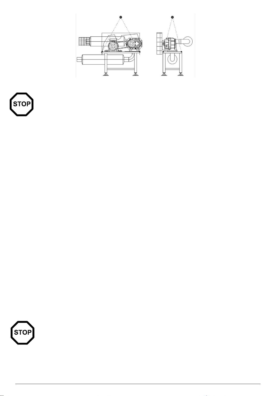
The pump can be lifted and handled using a fork-lift truck and hoisting means (e.g. ropes, hooks, etc.) suitably sized
BORA 163 HV - FP
BORA 163 HV - FP
BORA 233 HV → 1083 HV
BORA 233 HV → 1083 HV
Fixing point (with installed motor)
BORA MODEL
Fixing point (without motor)
A + B
163 HV
C + B
B + C
233 HV → 353 HV
E + D
A + C
463 HV → 1083 HV
E + D
BORA 243 FP → 543 FP /BORA 73HV-153HV
BORA 243 FP → 543 FP/BORA 73HV-153HV
Fixing point
(with installed motor)
BORA MODEL
Fixing point
(without motor)
(A + B) +
(C+D)
243 FP → 543 FP
73HV-153H
A + B
Fig. 2
Fig. 3
Tab. 3
Fig. 4
Tab. 4
for its weight (indicated in the technical data table and on the rating plate) and applied as indicated in the following
diagram to obtain the best harness in terms of safety and center of gravity.
High vacuum pumps, exhausters and blowers operating manual
Page 12
12
HOISTING PLANT ON BENCH
Fig. 5
WARNING
In order to transport the pump, we recommend you to prepare it as shown in the following paragraph.
4.4 – STORAGE
Shut down the inlet and outlet ports with the specific protections. The pump has to be stored in its packaging and kept
in covered, dry, protected places that are not exposed to bright sunlight, with temperatures in the range indicated in
point 3.3 of this manual..
If you are planning a long break before the assembly on the user system, moisten the internal parts with anti-rust oil.
4.5 – ENVIRONMENTAL CONDITIONS
The pump must be installed and used in a covered and adequately lit location. The installation area must meet all
requirements of height, air circulation and meet the requirements imposed by existing legislation.
Temperature, Humidity and Altitude
The corresponding limit values are shown in the technical specifications (10). Please contact the Supplier if
environmental conditions are different from those prescribed.
Lighting.
All areas must be illuminated evenly and sufficiently to ensure all operations included in this manual and must be
without shadows, reflections, glare or eyestrain.
4.6 – PUMP INSTALLATION
The pump can be installed and supported using the delivery flange or, alternatively, the appropriate feet. However,
it should be secured to a perfectly horizontal, solid surface in order to avoid tilting and/or subsidence in case of
transportation of the system user. If using feet to secure the pump, check that all four feet are resting on the surface (<
0,2mm) and if necessary use thicknesses before tightening them onto the supporting structure. We recommend that
you install the pump securing it by means of shock mounts.
In order to guarantee the perfect, safe running of the pump, position it according to the following guidelines:
• Leave sufficient space on the pump’s perimeter sides and make sure you keep the motor’s fan side free
following the indications in point 10 of this manual.
• Make sure the free space adjacent to the pump allows easy access to components for inspection or
maintenance and also allows access for suitable lifting equipment.
• Install the pump on a structure or system that does not transmit or amplify vibrations or sound emissions;
we recommend the use of anti-vibration systems.
• Ensure there is ventilation in the room or inside the machine housing the pump and prevent air coming in
from the motor cooling fans from stagnating in the room, changing the environmental conditions or causing
discomfort to personnel.
The position with horizontal axis flow and direction of rotation standard, usually adopted for direct drive, can find application
in compact systems.
WARNING
Store the pump on a perfectly horizontal surface. Tilting could cause the oil inside the gear and bearing
casings to enter into the pump work chamber.
High vacuum pumps, exhausters and blowers operating manual
Page 13

13
Installation with horizontal f/flow
Installation with vertical f/flow
Fig. 6
DANGER
Use an intake filter to protect the pump from dust, sand, masonry debris, cutting filaments and threadings,
drops and welding dirt and sealant residue produced when connecting the pipes that could damage rotor
lobes causing seizure.
DANGER
Position the pump and relative control systems in order to see the installation area during any operation in
order to prevent the machine from starting up while personnel are still carrying out work on it.
Failure to comply with these points could cause serious injury.
WARNING
Installing the pump on misaligned surfaces can jeopardize its operation when tightening the bolts.
When tightening make the shaft turn manually to check that the initial slipping remains unchanged.
WARNING
Do not install the pump in an area with dust or other materials that could clog and/or quickly cover the
motor fan or pump’s cooling surfaces.
4.7.1 - MOTOR INSTALLATION ON BLOWERS AND EXHAUSTERS
The blower can be installed and supported using either the discharge flange or the proper feet. If the feet are used, before
tightening them to the frame, check that all four feet touch properly the base (< 0.2 mm) and, if needed, use appropriate
shims.
WARNING
If the blower is placed on an irregular base, malfunctioning may be occur. During tightening operation
check the free manual rotation of the shaft.
Use just one bolt per foot. The alignment of the coupling or of the belts and the tensioning of the belts shall be carried out
as prescribed by the supplier of these components. The blower may transmit vibrations to the frame on which it is installed.
If they give problems to the surrounding environment and / or machinery , please isolate the frame with damping devices.
WARNING
Excessive tension of the belts can damage the compressor and/or the motor.
Excess of clearance in the coupling or worm flexible coupling causes damages to the blower not covered
by warranty.
High vacuum pumps, exhausters and blowers operating manual
Page 14

14
BELT DIRECTION
BORA HV 73
M90/2 B5 IEC-72, 1.5-2,7 kW 50-60Hz
BORA FP 243
M90/2 B5 IEC-72, 1.5-2,7kW 50-60Hz
BORA HV 103
M90/2 B5 IEC-72, 2.2-2.7kW 50-60Hz
BORA FP 363
M90/2 B5 IEC-72, 2.2-2.7kW 50-60Hz
BORA HV 163
M90/2 B5 IEC-72, 2.2-2.7kW 50-60Hz
BORA FP 583
M90/2 B5 IEC-72, 2.2-2.7kW 50-60Hz
BORA HV 233 - 293
M100/2 B5 IEC-72, 3.0-3.6kW 50-60Hz
BORA FP 813
M100/2 B5 IEC-72, 3.0-3.6kW 50-60Hz
BORA HV 353 - 463
M112/2 B5 IEC-72, 4.0-4.8kW 50-60Hz
BORA FP 1043
M100/2 B5 IEC-72, 3.0-3.6kW 50-60Hz
BORA HV 673
M132/2 B5 IEC-72, 5.5-6.6kW 50-60Hz
BORA FP 1263-1673
M112/2 B5 IEC-72, 4.0-4.8kW 50-60Hz
BORA HV 883 - 1083
M132/2 B5 IEC-72, 7.5-9kW 50-60Hz
BORA FP 2313
M132/2 B5 IEC-72, 5.5-6.6kW 50-60Hz
Fig. 8 - direction of the V-Belt for 103 series
Fig.8.1 - - direction of the V-Belt for 103-883 series
233 HV - 1083 HV
813 FP - 2313 FP
73HV - 163 HV
243 FP - 583 FP
X
50 mm
42 mm
Tightening torque (A)
20 Nm
20 Nm
Tab. 5
Fig. 9
Tab. 6
Fig. 8 shows the only correct direction of the V-Belt for the specified specified series.
WARNING
Any other direction of the V-Belt may reduce bearing’s life and is not covered by warranty.
4.7.2 - MOTOR INSTALLATION ON BOOSTER HV AND FP SERIES
It is possible to install any type of electric or hydraulic motor that has the features described in the table of technical
data, with flange and shaft corresponding to:
ATTENZIONE
The motor coupling alignment should be carried out following the indications and measures indicated
below. The excessive clearance in the coupling and flexible couplings cause damages to the pump
that are not covered by the warranty.
Fit the half-coupling on the motor shaft until you reach the stated measure.
Tighten the screws “A”, applying the torque indicated to firmly fix the half-coupling to the motor shaft.
4.8 - USER SYSTEM
Make sure that no harmful substances contaminate the user system during installation. If you wish the system to
maintain vacuum even when pump is stopped, install a cutoff valve between pump and system.
High vacuum pumps, exhausters and blowers operating manual
Page 15

15
4.9 - CONNECTION
DANGER
Pump connections should be performed by skilled and trained personnel only.
4.9.1 - INTAKE AND OUTLET CONNECTIONS
All the pump’s openings are protected in order to prevent extraneous parts entering it. Only remove these protections
positioned on the intake and outlet points shortly before connecting to the user system. Using thick steel hoses
reduces the noise. Clean the hoses thoroughly especially remove welding fluxes to prevent foreign bodies from
reaching the pump and damaging it.
The connection to the user system (intake and outlet) should be carried out using strain neutralizers to prevent
tensions and/or deformations on the flanges. The couplings and piping should have a diameter equal or greater than
that of the pump intake/outlet opening..
WARNING
Thoroughly clean the intake and delivery flanges checking the status of the seal surfaces and make sure
that the couplings, piping or flanges connected to the pump intake/outlet are firmly tightened and that there
are no leaks.
The weight of pipes or any expansions must not burden the pump connections. We recommend you to carry out the
final connection to the pump using flexible pipes or fittings, thus avoiding rigid connections that can induce tensions
and cause harmful vibrations. It is important to tighten all pipes and couplings. Extreme long piping or one with a
diameter that is too small and with tight, regular curves reduces the pump’s performance.
Employing the machine as a blower, the use of thick-walled steel pipes has a lowering noise effect. Clean accurately the
pipes, removing, in particular, welding debris particles in order to avoid that foreign objects get inside the compressor and
damage it. Avoid narrowing the pipes and creating short radius curves. The weight of the pipes must not rest on the
compressor but must be supported separately.
An expansion joint, on the pressure side, eliminates pressure on the machine caused by thermal elongation of the pipes.
We recommend the fitting of accessories described in chapter 5 ‘ACCESSORIES’.
WARNING
Little amounts of fluid are enough (coming from the container or the piping) to produce blows on the rotors
inside the pump chamber. The blows can deform the rotors and cause the pump to seize. Possibly take
suitable protective measures on the piping of the intake line (e.g. separator, T- fittings, etc..).
WARNING
Make sure that vibrations or loads are not transmitted on the pump’s attachments.
WARNING
Use an intake filter, especially if the pump works with unclean air flows.
4.9.2 - ELECTRIC CONNECTION
WARNING
Check that voltage and frequency correspond to values shown on the motor plate.
The connection cable must be in line with the power absorbed by the motor pump (the pump’s absorption levels
are shown on the electric motor plate) bearing in mind the environmental operating conditions. Use the cable clamp
openings to pass the power cables inside the terminal board.
DANGER
Always earth the pump. Always connect the earth cable to the relative clamp before connecting to the
mains supply and check the dispersion capacity.
High vacuum pumps, exhausters and blowers operating manual
Page 16

16
Fig. 10
DANGER
Lay the pump power cable in such a way that it cannot cause the risk of tripping or falling or can be
damaged.
Always install an electric protection system between the pump and power supply; the pump’s absorption levels are
shown on the electric motor plate. The fuses do not protect the motor, but are only a protection against short-circuiting.
Select a suitable kind and size of fuses bearing in mind the peak current, especially in the case of direct start-up.
The protection with motor protection is essential against overloading risks, in the absence of a network phase,
excessive variation of the voltage or pump block. Adjust the motor protection on the plate’s nominal current as the
maximum level. The pump is normally supplied without an electrical cable and switch. For electrical connection, see
the diagram contained within the terminal board or on the motor rating plate.
DANGER
The rotation direction determines also the flow direction (see figure 10).
Check that the direction of rotation is correct before starting the pump for the first time or after resetting the
electrical connections.
WARNING
In the event of incorrect rotation direction wait for the pump to come to a complete halt, before changing the
connection and supplying power again.
In the matter of blowers and exhausters, the correct rotation direction can be verified with a brief start-up.
Briefly start up the Bora pump motor, observing that the rotation direction of the motor cooling fan is counterclockwise
(arrow). If this is not the case disconnect the network cables and reverse the two phases. You can see if the sense of
rotation is correct, as soon as the rotation begins. Turn it off immediately and go on with the installation procedures.
In the matter of booster, the correct rotation direction can be verified bringing the pressure inside the pump to a value of
< 20 mbar, by switching on the primary pump. Then briefly start up the Bora pump motor and immediately turn it off,
making sure that the rotation direction of the motor cooling fan is counterclockwise (arrow). If this is not the case
disconnect the network cables and reverse the two phases.
High vacuum pumps, exhausters and blowers operating manual
Page 17
17
5 – ACCESSORIES
Fig. 11
Fig. 12
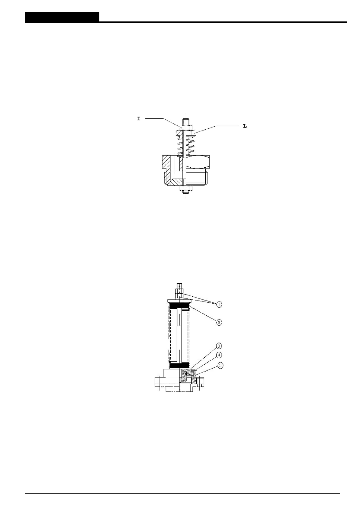
5.1 – RV VACUUM RELIEF VALVE SETTING INSTRUCTIONS
The vacuum relief valve is an accessory available for blowers and exhausters in order not to generate an excessive
lowering of absolute pressure on suction side. Fit the valve on suction side of the blower/exhauster and prearrange a
pressure take-off closed to the suction side of the same. Release screw ‘I’ and discharge the valve spring by screwing off
nut ‘L’.
Start the blower and throttle the suction upstream the valve till you get the worst working conditions (usually pipe line
completely closed ).
Screw in nut ‘L’ till you get the maximum vacuum allowed; this can be noticed from the pressure intake on blower's head.
Tighten nut ‘I’ by keeping steady nut ‘L’.
Remove the choking from suction pipe. See fig. 11.
5.2 – SETTING OF THE OVER PRESSURE VALVE
The overpressure valve is an accessory available for blowers in order to avoid overloading of the pump, if there were
any conditions of excessive backpressure in delivery.
The valve is usually supplied non-adjusted.
The setting adjustment is to be performed on the operating system: start the system with a minimum pre-load of the spring
increasing it by tightening the nut 1 until the desired pressure is reached. Then rotate the threaded ring 5 in order to
stabilize the discharge. Tighten finally the nut 1 and bolt 4 (Fig. 12).
5.3 – AIR FILTER ON SUCTION
It is always recommended but it is needed when the blower works in a dusty environment or when there is risk of foreign
objects. (filtering degree < = 0,005 mm)
5.4 – CHECK VALVE
It prevents counter flow or attraction of foreign objects or liquid into the machine.
5.5 – SILENCERS
The noise emission level of the compressor depends on the rotation speed and the back pressure.
In case of use as a blower, it is necessary to apply a silencer on the intake side in order to reduce the noise. A further
reduction is achieved with a silencer on the delivery side.
High vacuum pumps, exhausters and blowers operating manual
Page 18

18
WARNING
Fig. 10
The silencers must be installed on the blower flanges making sure that their weight is not supported by the
machine itself and they do not cause any deformation to the machine. During flange’s bolts tightening
operation check the free manual rotation of the shaft.
5.6 - SOUNDPROOFING BOOTH
In case of high speed and/or high back-pressure the use of a soundproofing booth may be needed.
WARNING
Said booths shall allow air circulation for an appropriate cooling of the machine. Forced ventilation may be
necessary.
5.7 - ANTISHOCK MOUNTS
They allow to damp the vibration that otherwise would be transmitted to the foundation. They are recommended for the
positioning between pump bracket and support plane for blowers and exhausters.
5.7.1 - ELASTIC HOSE
Must be used in case of antishock mounts: it avoids the transmission of mechanical vibrations to the pipes and allows
their free heat elongation.
5.8 - VACUUM AND PRESSURE GAUGES
Their use is recommended to check that the system is operating correctly and to check the adjustment of the overpressure valve.
5.9 - CHOKED AIR FILTER GAUGE
It is particularly recommended for machines that are not constantly checked or closed in a soundproofing booth.
A pressure switch installed in the appropriate boss on the suction flange shall actuate an alarm signal and in case
shut off the motor, keeping under control the vacuum level given by filter.
5.10 – MOTOR ELECTRICAL PROTECTION
On the electric feed line, install a thermo-magnetic switch properly adjusted as a protection against feed problems.
5.11 - ANTI ACCIDENT DRIVE COVER
If the coupling between the pump and the electric motor is not made by Pompetravaini - Bora, please note that, in all
cases a protection must be provided in order to avoid contact with moving parts using a cover conforming to the
regulations in force. Pompetravaini - Bora does not assume any responsibility for anti accident drive not manufactured
or supplied by itself.
6 – INSTRUCTIONS FOR USE
6.1 - OPERATION
Blowers, exhausters and vacuum pumps described in this manual are rotary machines equipped with lobe rotors,
symmetrically arranged and counter rotating, contained inside a housing. The rotor rotation is synchronized by means of
a gear transmission so as to move forward without a mutual contact with little clearance between them and with respect
to the housing. The operating principle is indicated below.
High vacuum pumps, exhausters and blowers operating manual
Page 19
19
In stage 1 the volume generated by the rotor rotation increases. As the rotor rotation continues, in stage 2 the two
volumes are isolated and transferred to the outlet area. Then, in stage 3 these volumes come into contact with the
delivery flange. Thanks to the operation without contact inside the chamber the lobe volumetric pumps can work at
high speeds. In this way you can obtain high flows even using small pumps.
WARNING
The pressure differential and the compression ratio between the intake and outlet sides represent a limit
for the volumetric pumps described in this manual. Exceeding the allowed pressure differential causes the
pump to overheat and/or its seizure
The use of High vacuum pumps Booster HV must be installed in series with a primary vacuum (backing) system that
guarantees a Maximum absolute pressure of 50 mbar in order to avoid overheating of the pump.
It is suggested that the starting is operated by a vacuum switch placed between the booster and the backing pump.
It is possible to use by-pass valves in order to drive short time vacuum cycles: long lasting gas recirculation may cause
overheating of the pump.
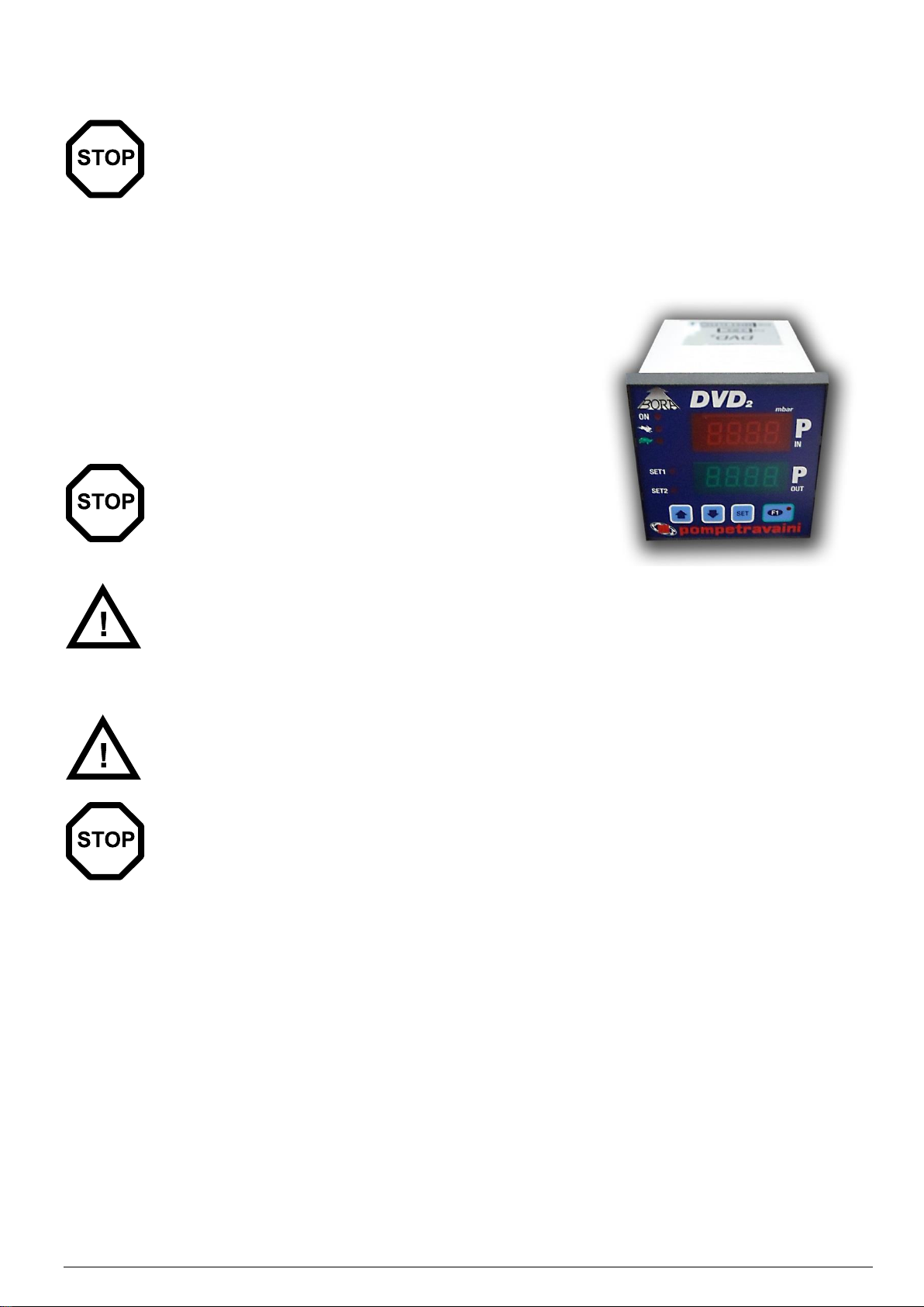
Performances active control through frequency inverter is maximized by
POMPETRAVAINI - BORA DVD-2 system that guarantees minimum time
to vacuum and safety of the pumps.
For more information please contact POMPETRAVAINI - BORA.
WARNING
Operation without lubricant causes serious damage to the
pump.
DANGER
The pump may reach high temperatures when operating. Special precautions should be taken in order to
avoid personnel and/or equipment and electric parts nearby coming into contact with it.
6.2 – START UP
DANGER
The pump can only be started up after all the indications, requirements and prohibitions indicated in this
manual have been carefully read, understood and respected.
WARNING
Regarding HV and FP volumetric pumps, start up the volumetric pump only after the primary pump has
brought the system to the correct outlet pressure specified for operating.
Checks to be performed before start-up:
If an excessively long period of time has elapsed before starting up the pump, check its preservation status and
operation. Remove any dust deposits from the external surfaces and check that the rotor lobes of the pumps can
turn freely without obstacles and that they are not oxidized.
The pump is supplied complete with lubricating oil inside the casings of gears and bearings. For the HV and FP
pumps series also in the motion transmission shaft seal lubrication bell. However, check that the visible oil level is
correct using the oil sight glass and vessels. If necessary, top up the oil following the indications given in point 7
(Maintenance) of this manual.
Make sure that the pump’s intake and outlet are not blocked by connectors and/or protections and/or closure
valves.
Check that the adjustment of the motor protection corresponds with the motor’s nominal current indicated on the
relative plate.
Check that the room temperature and that of the conveyed gas intake is within the levels indicated in point 10 of this
manual.
After carrying out the preliminary controls listed above, the pump can be started up.
With the started up pump check that the electric motor absorption complies with the values indicated on the
motor plate.
High vacuum pumps, exhausters and blowers operating manual
Page 20
20
WARNING
In order to reducing energy consumption and not damaging the pump, it is advisable not to start up
more than 6 times / hour and that they are equally distributed.
DANGER
The pump working temperature depends on the characteristic of the processed fluid. High temperature levels
can be due to room temperature or gas intake that is too high, pressure differential that is greater than that
allowed, low or high oil level, installation is in constricted spaces, exposure to direct sun rays, dust deposits
on the motor’s cooling fan or on the fan cover casing.
DANGER
Full rotation speed pump operation must be without vibration or unusual noise. If these are present, stop
the pump immediately, search for the cause and eliminate it.
WARNING
Use the pump only in the working conditions indicated in this manual. If the working parameters change
(for example intake pressure, intake temperature, ratio with the primary pump) the volumetric and primary
pump could overheat and get seriously damaged.
Starting acceleration must not exceed the torque T Max (Nm) obtainable from performance charts as follows:
P - Power (kW) at max pressure - Max Speed
n - Revolution per minute (rpm)
T max (Nm) = P (kW) x 20000 n (rpm)
Start / delta starting is recommended.
If the blower is started against full counter-pressure, it will be impossible to operate the star-delta starting method due to
lack of torque should the start up be with star-delta, the blower should then be fitted with a centrifugal coupling or, even
better, a clutch coupling, to be engaged when the motor has reached its full power.
6.3 – STOP
The pump must be stopped by cutting off the power supply and isolated from the system by closing the valve (see 5).
WARNING
Per le pompe delle serie Booster HV/FP, spegnere prima la pompa volumetrica e successivamente la
pompa per vuoto preliminare.
6.4 - DECOMMISSIONING AND PROLONGED STOPPAGE
If the pump is placed out of order and/or stopped for a prolonged period of time, proceed as follows:
• Stop it following the procedure indicated in point 6.3 of this manual
• Insulate the electrical power supply
• Insulate it from the user system cutting off the intake and outlet connection
• Gradually release the pressure or vacuum that may be inside
• Disconnect the connections to the system
• Shut off the intake and outlet using the specific protections
High vacuum pumps, exhausters and blowers operating manual
Page 21
21
7 - MAINTENANCE
7.1 - GENERAL WARNINGS
WARNING
It is important and essential that the operating pump is periodically inspected in order to avoid breakages
that can directly or indirectly cause damage to the pump itself or create hazardous situations for personnel.
For good maintenance:
• Immediately verify the causes of any malfunctions (excessive noise, overheating, etc.)
• Pay particular attention to the efficiency of safety devices
• Make use of all documentation provided by the Supplier (instruction manuals, wiring diagrams, etc.)
• Use only appropriate tools and original spare parts
• Use suitable individual protective equipment.
If failing to understand fully the information or procedures contained in this chapter, contact Pompetravaini - BORA for
clarification before proceeding.
Only trained or authorized personnel have the necessary expertise to perform tasks with the skills appropriate for
intervention.
DANGER
Do not perform any type of operation, modification and/or repair of any kind, except for those listed in this
manual.
DANGER
All maintenance work must be carried out with the pump disconnected from the power supply and
measures must be adopted to prevent it being reconnected. Only open the terminal board of the electric
motor after ensuring that there is definitely no voltage present. Attach a notice to the pump’s system
command and command elements which states.
DANGER
The user is forbidden to carry out repair or maintenance work that requires the replacing of seized parts
that may have become deformed to the extend that they become unusable. In these cases, contact the
Supplier or authorized dealer for assistance.
DANGER
If the pump maintenance has been performed in a manner inconsistent with instructions, with non-original
spare parts or otherwise so as to impair its integrity or modify its characteristics, Pompetravaini - BORA will
be released from any liability relating to the safety of persons and malfunction of the pump.
High vacuum pumps, exhausters and blowers operating manual
Page 22
22
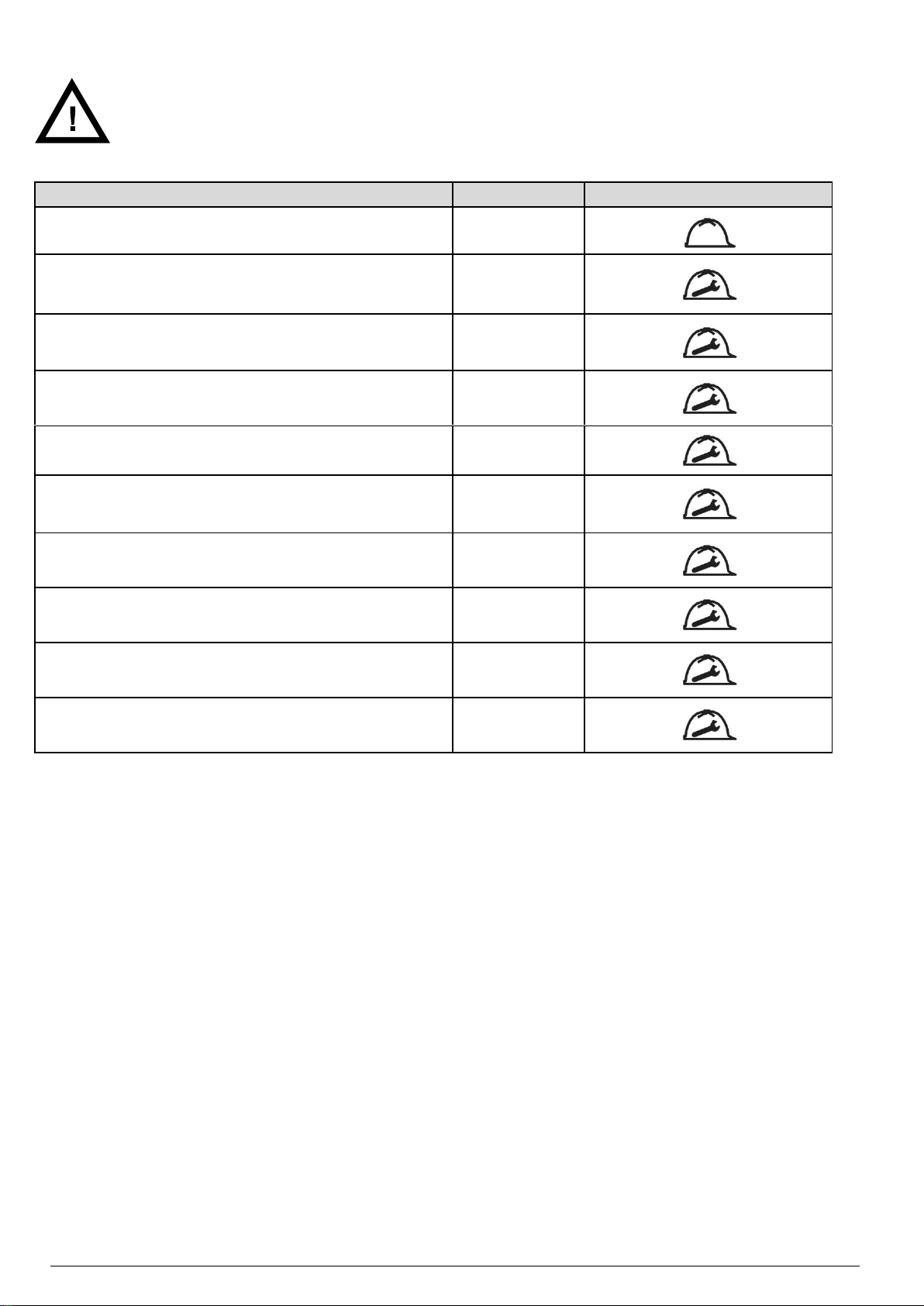
7.2 – OPERATIONS TABLE
OPERATION TYPE
FREQUENCY
OPERATOR QUALIFICATION
Check of the lubricant levels
24 h
Replacement of the 1st supply gear and bearing oil
1 x 500 h
Replacement of the 1st supply shaft seal oil (HV/FP series only)
1 x 500 h
Clean the motor fan protection
1000 h
General external cleaning of the pump
1000 h
Check of the transmission elastic element
2500 h
Replacement of the gear and bearing oil
5000 h
Clean the suction filter
According
to the system
Check of the transmission belts
2500h
Replacement of the shaft seal oil (HV/FP series only)
5000 h
Tab.7
The following table shows all required periodic operations to maintain pump efficiency.
DANGER
Wear suitable protection equipment when carrying out maintenance work
More frequent maintenance may be necessary depending on the kind of use and environment where the pump is
installed (high temperature of intake gases and/or workplace, presence of condensable vapors in the intake gases,
very dusty workplace, etc.).
7.2.1 - CHECK OF THE LUBRICANT LEVELS
Check that the lubricating oil level of the gears and bearings reaches half of the oil sight glass. Alternatively follow the
instructions provided in this section. Check oil conditions. When dark or cloudy, oil has been contaminated and must
be changed. Regarding HV/FP pumps series, If oil topping up is frequent it means that the pump internal seals might be
damaged. Check that the lubricating oil level of the front seal of the motion inlet shaft respects the correct level indicated
in the expansion vessel:
• Cold machine – 1/4 max
• Hot machine – 3/4 max
A reduction of the oil level in the oil viewer indicates that the seals of the shaft are damaged. If with the oil level decreasing
in the oil viewer there are no oil leaks or spillage under the motor coupling bell, the internal seal on the shaft might be
defective and the oil might flow inside the casing of the bearings making the lubricant level rise. If this is the case
immediately turn off the pump to repair it. If instead, with the oil level decreasing in the oil viewer there are oil leaks or
spillage under the motor coupling bell, the external bell lip seal might be defective.
7.2.2 - REPLACEMENT OF THE 1ST SUPPLY GEAR AND BEARING OIL
The bearing life span depends also on the lubricant contamination. The lack of contaminants in the lubricating oil is
essential. The oil has to be changed after the first 500 hours and then periodically when reaching 5000 hours of use or
at least every 18 months, whichever comes first. The oil needs to be replaced more frequently in case of cyclic operation
when frequently switching from the atmospheric pressure to the working pressure.
High vacuum pumps, exhausters and blowers operating manual
Page 23
23
WARNINGE
Use exclusively the following oils to lubricate the pump bearings:
• MOBIL SHC 624.
• TEXACO CETUS PAO 46
Change the gear and bearing oil as follows:
Disconnect the pump from the mains and bring the work chamber to the atmospheric pressure
Undo the oil filler plug
Get a container large enough to hold all oil and open the oil drain plug
Drain out all oil
Close drain plug and fill in fresh oil through the filler plug up to mid-range on the oil sight glass.
Close the oil filler plug and remove any oil spillage from the pump and/or floor
Connect to mains again and verify correct rotation direction of the pump (see 4.9)
WARNING
Regarding HV/FP pumps series, the oil filler plugs should be leak-tight. During vacuum running the
introduction of outside air through plug leakages could cause air containing oil to enter into the pump work
chamber through the rotor seals increasing the consumption of oil in the pump.
WARNING
A too low oil level jeopardizes the lubrication of gears and bearings, while a too high level might
contaminate the oil free work chamber of lobe rotors.
DANGER
Wear appropriate personal protection equipment to perform said operations.
DANGER
Comply with local regulations regarding the collection and disposal of used or polluted oil.
7.2.3 - REPLACEMENT OF THE 1ST SUPPLY SHAFT SEAL OIL
The pump is supplied complete with oil of first topping up. Bearing’s life is also depending on the degree of contamination
of the lubricant. It is vital that the oil does not get contaminated and it must be changed after the first 500 hours, and then
periodically every 5000 hours of usage or at least every 18 month.
Change the gear and bearing oil as follows (repetition of the previous chapter):
Disconnect the pump from the mains and bring the work chamber to the atmospheric pressure
Undo the oil filler plug
Get a container large enough to hold all oil and open the oil drain plug
Drain out all oil
Close drain plug and fill in fresh oil through the filler plug up to mid-range on the oil sight glass.
Close the oil filler plug and remove any oil spillage from the pump and/or floor
Connect to mains again and verify correct rotation direction of the pump (see 4.9)
WARNING
Use exclusively the following oils to lubricate the pump bearings:
• MOBIL SHC 624.
• TEXACO CETUS PAO 46
Check frequently the oil level trough the transparent plug. If adding is needed use upper vent plug; lower plug to drain.
The position of the plugs is shown in the dimensional drawings later in this manual.
The pump is supplied complete with oil of first topping up also in the cavity of the pump/motor connection where
the
motion transmission shaft seal is housed.
WARNING
To lubricate the motion transmission shaft seal of the pump use the same type of oil used for the gears
and bearings, such as:
• MOBIL SHC 624.
• TEXACO CETUS PAO 46
High vacuum pumps, exhausters and blowers operating manual
Page 24
24
7.2.4 - CLEANING THE MOTOR FAN PROTECTION
Cleaning the motor fan protection is done in order to remove any dust. This must be done using a blow of compressed
air and a dry cloth. Do not use fluids or substances other than those indicated.
7.2.5 - GENERAL EXTERNAL CLEANING OF THE PUMP
General cleaning of the pump is done in order to remove any dust. This must be done using a blow of compressed air
and a dry cloth. Do not use fluids or substances other than those indicated.
7.2.6 - CHECK OF THE TRANSMISSION ELASTIC ELEMENT
Check according to the frequency indicated in the table in point 7.2 of this manual, or at least once a year, the wear
status of the elastic element of the motion transmission coupling of the pump/motor and replace it if necessary.
7.2.7 - REPLACEMENT OF THE GEAR AND BEARING OIL
To replace the bearing oil proceed as indicated in point 7.2.2 of this manual.
7.2.8 - REPLACEMENT OF THE SHAFT SEAL OIL IN BOOSTER HV AND FP
To replace the shaft seal oil in booster HV and FP proceed as indicated in point 7.2.3 of this manual.
7.2.9 - FILTER MAINTENANCE
Replace the paper filters or wash the spongy material filters, with frequency proportional to the degree of environmental
contamination of the working area or whenever the vacuum gauge on the intake shows loss of pressure.
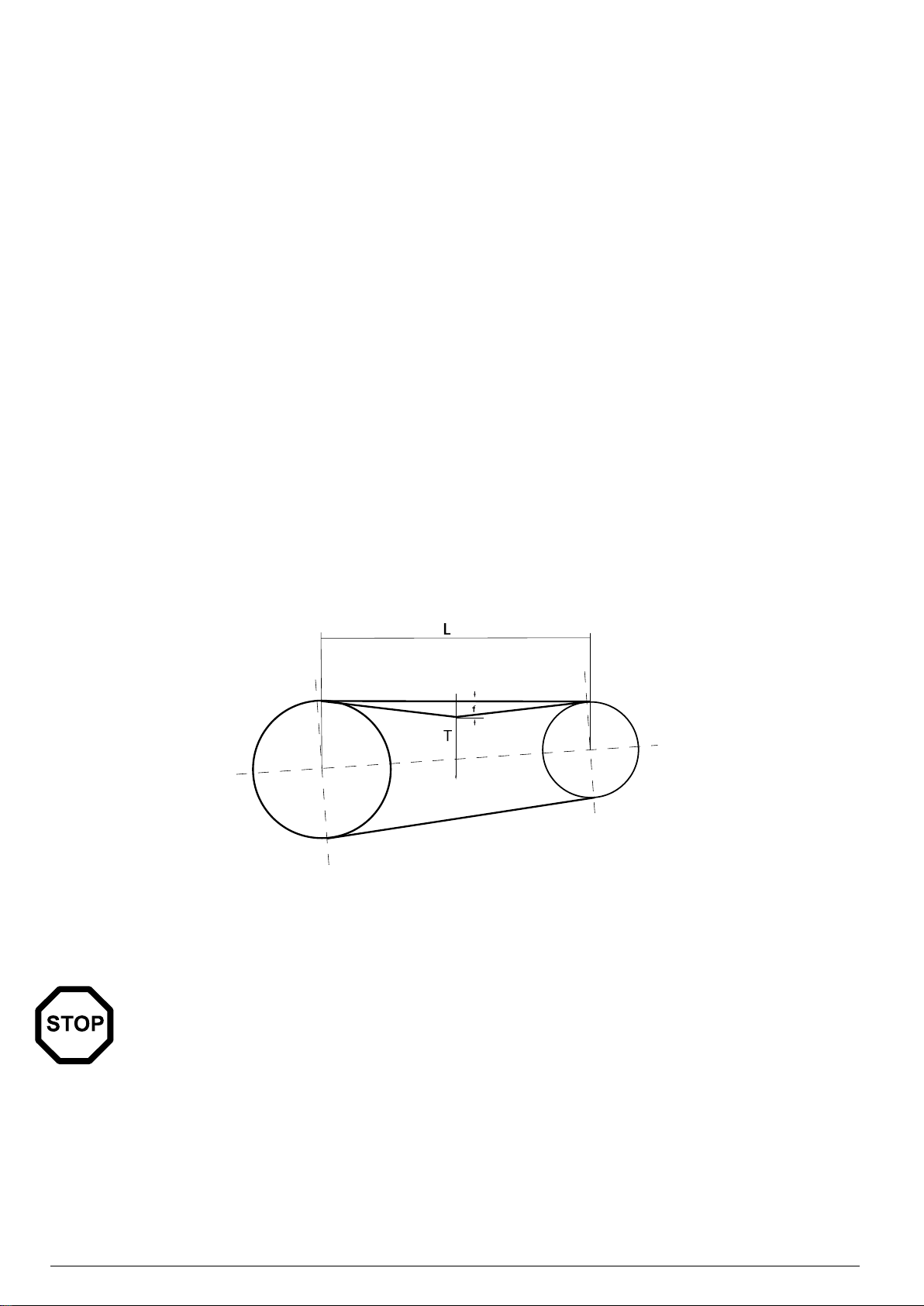
7.2.10 - TRASMISSION
Check every 2500 hours of work or at least once a year the wear of the rubber blocks in the flexible coupling and in case
replace them. In case of V-belt drive check wear and tension.
The right tensioning of the V-belts is reached acting on the motor slide as follows (see figure below). Apply a T force
square to the centre point of the free part of the belt L' in order to obtain an elastic deformation f of a distance equal to
1.5% of the free part itself. SPB V-belt profile, if T load is higher than 6 kgf the belt is over tensioned: release the tension;
if T load is lower than 3.7 kgf the belt is under tensioned: tight the tension.
For different V-belts profiles see specific manufacturer 's manual.
7.3 – PAINTING
The machine is originally painted with properly selected paint that allows the highest heat exchange with the air. Even in
case of esthetical deterioration we advise to have paint retouches made only in case of a reconditioning performed by
Pompetravaini - BORA.
WARNING
Do not re-paint the compressor in order not to jeopardize the correct heat exchange needed in the heaviest
duty use of the machine.
High vacuum pumps, exhausters and blowers operating manual
Page 25
25
PROBLEMS
LIST OF POSSIBLE CAUSES
Vain or scarce performance, insufficient outlet pressure.
1, 2, 3, 4, 5, 6, 7, 8, 9, 10, 11, 12, 17
Excessive performance, outlet pressure higher than expected.
3, 7, 13, 14
High power absorption.
1, 2, 3, 5, 7, 8, 9, 13, 14, 15, 16, 19
Raised noise and high vibrations.
3, 4, 11, 13, 14, 19, 20, 21, 22, 23, 24, 28
Overheating.
1, 2, 3, 5, 13, 14, 15, 16, 17, 18, 19
Nonfunctional seal system.
15, 25, 26, 27
CAUSES
REMEDY
PERSONNEL
1
Too small diameter of piping.
Replace piping with larger diameter
ones.
Qualified technician
2
Obstructed piping.
Remove the obstructions.
Operator
3
Not correctly adjusted valve.
Adjust the valve (see 5,2).
Qualified technician
4
No airtight machinery.
Look for the leaks and remove them.
Qualified technician
5
Intake filter clogged.
Clean or replace the filter (see 7.2.9).
Qualified technician
6
Speed of rotation lower than expected.
Check tension belts, if they are slack,
regulate (see 7.2.10). Check their
sizing, improve if they are undersized.
Check the ratio of pulleys and correct,
if it is wrong.
Qualified technician
7
Inappropriate Blower/booster sizing.
Check the machine selection and
correct it.
Qualified technician
8
Electric motor improperly connected.
Check the electric connection and the
rotation direction. If it is wrong, correct.
Qualified technician
9
Wrong supply voltage.
Check the electric motor supply. If it is
wrong, correct.
Qualified technician
7.4 – SPARE PARTS
In order to replace the pump parts we recommend the use of Original Spare Parts. When purchasing spare parts
always quote the pump’s Type and Serial number (you will find these on the identification plate) .
Pompetravaini - BORA disclaims all responsibility for any deterioration of pump performance or for damages caused
due to use of non original spare parts.
8 – HOW TO RETURN THE PUMP
The product may only be returned after prior agreement with the Supplier, who will provide the authorization number
that must accompany the material delivered and should be duly complete in its entirety.
9 – DISMANTLING
Demolition of the pump must be performed by authorized technicians.
Metal parts can be disposed of as scrap metal.
All materials deriving from demolition must be disposed of according to regulations in the country where the pump will
be demolished.
DANGER
Disposal operations involve risks of cutting, shavings projection, entanglement, contact with moving parts
and contact with chemicals. Operators should use the appropriate personal protective equipment.
9.1 – TROUBLE SHOOTING BLOWERS
High vacuum pumps, exhausters and blowers operating manual
Page 26

26
10
Damaged motor.
Check the motor operation. Replace, if
it is damaged.
Qualified technician
11
V-belts degraded.
Check tension V-belts and correct it, if
necessary. Replace V-belts if they are
consumed.
Qualified technician
12
Speed of motor rotation is not sufficient.
Check direction and speed of rotation.
Check the electrical connection and
correct it, if necessary.
Qualified technician
13
Speed of rotation is higher than the target.
Check the ratio of pulleys and correct,
if it is wrong.
Qualified technician
14
Speed of motor rotation is excessive.
Check the speed of rotation. Check the
electrical connection and correct it, if
necessary.
Qualified technician
15
Exceeding quantity of lubricant in the casing.
Drain any excess lubricant, restoring
the correct level.
Qualified technician
16
Deformation caused by foot tightening.
Check the uniformity of the supporting
surface of feet machinery (within 2
mm). If necessary, use some shims to
correct it.
Qualified technician
17
Intaked gas temperature too high.
Check the suction conditions are within
the established parameters (see
3,1,2). Correct, if necessary.
Qualified technician
18
Too high machine-room temperature.
Machine-room has to be appropriately
ventilated to dissipate the produced
heat. If ventilation is deficient, correct.
Operator
19
Frictions inside the blower/booster.
Stop the machine and rotate slowly
by hand. If there is friction or contact
between the parties, call assistance.
Assistance
20
Rotors out of phase after seizure.
Stop the machine and rotate slowly
by hand. If there is friction or contact
between the parties, call assistance.
Assistance
21
The contact of rotors is caused by fouling.
Stop the machine and rotate slowly
by hand. If there is friction or contact
between the parties, call assistance.
Assistance
22
The contact of rotors is caused by oxidation.
Stop the machine and rotate slowly
by hand. If there is friction or contact
between the parties, call assistance.
Assistance
23
Bearings or gears deterioration is caused by
lack of lubricant.
Stop the machine and rotate slowly
by hand. If there is friction or contact
between the parties, call assistance.
Assistance
24
Blower/booster damage is caused by seizure.
Stop the machine and rotate slowly
by hand. If there is friction or contact
between the parties, call assistance.
Assistance
25
No airtight plugs or seals.
Pick out the damaged external
tightness elements and replace them.
Qualified technician
26
Damaged internal tightness organs.
Stop the machine and call assistance.
Qualified technician
27
Clogged vent plugs.
Clean or replace vent plugs.
Qualified technician
28
Degraded silencers.
Replece the degraded silencer
components.
Qualified technician
High vacuum pumps, exhausters and blowers operating manual
Page 27

27
9.2 – TROUBLE SHOOTING EXHAUSTERS OR AC
PROBLEMS
LIST OF POSSIBLE CAUSES
Vain or scarce performance, insufficient outlet pressure.
1, 2, 3, 4, 5, 6, 7, 8, 9, 10, 11, 12, 17
Excessive performance, outlet pressure higher than expected.
3, 7, 13, 14
High power absorption.
3, 4, 5, 7, 8, 9, 13, 14, 15, 16, 19, 20
Raised noise and high vibrations.
3, 4, 13, 14, 20, 21, 22, 23, 24, 25, 29
Overheating.
1, 2, 3, 13, 14, 15, 16, 17, 18, 19, 20
Nonfunctional seal system.
15, 26, 27, 28
CAUSES
REMEDY
PERSONNEL
1
Too small diameter of pipes.
Replace piping with larger diameter
ones.
Qualified technician
2
Obstructed piping.
Remove the obstructions.
Operator
3
Not correctly adjusted valve.
Adjust the valve (see 5,2).
Qualified technician
4
No airtight machinery.
Look for the leaks and remove them.
Qualified technician
5
Intake filter clogged.
Clean or replace the filter (see 7.2.9).
Qualified technician
6
Speed of rotation lower than expected.
Check tension belts, if they are slack,
regulate (see 7.2.10). Check their
sizing, improve if they are undersized.
Check the ratio of pulleys and correct, if
it is wrong.
Qualified technician
7
Inappropriate Blower/booster sizing.
Check the machine selection and
correct it.
Qualified technician
8
Electric motor improperly connected.
Check the electric connection and the
direction of rotation. If it is wrong,
correct.
Qualified technician
9
Wrong supply voltage.
Check the electric motor supply. If it is
wrong, correct.
Qualified technician
10
Damaged motor.
Check the motor operation. Replace, if
it is damaged.
Qualified technician
11
V- belts degraded.
Check tension V-belts and correct it, if
necessary. Replace V-belts if they are
consumed.
Qualified technician
12
Speed of motor rotation is not sufficient.
Check direction and speed of rotation.
Check the electrical connection and
correct it, if necessary.
Qualified technician
13
Speed of rotation is higher than the target.
Check the ratio of pulleys and correct, if
it is wrong.
Qualified technician
14
Speed of motor rotation is excessive.
Check rotation speed. Check the
electrical connection and correct it, if
necessary.
Qualified technician
15
Exceeding quantity of lubricant in the casing.
Drain any excess lubricant, restoring
the correct level.
Qualified technician
16
Deformation caused by foot tightening.
Check the uniformity of the supporting
surface of feet machinery (within 2
mm). If necessary, use some shims to
correct it.
Qualified technician
High vacuum pumps, exhausters and blowers operating manual
Page 28

28
17
Intake gas temperature too high.
Check that the suction conditions are
within the established parameters (see
3,1,2). Correct, if necessary.
Qualified technician
18
Too high machine-room temperature.
Machine-room has to be appropriately
ventilated to dissipate the produced
heat. If ventilation is deficient, correct it.
Operator
19
Cooling air filter clogged.
Replace filter cartridge.
Operator
20
Frictions inside the blower/booster.
Stop the machine and rotate slowly
by hand. If there is friction or contact
between the parties, call assistance.
Assistance
21
Rotors out of phase after seizure.
Stop the machine and rotate slowly
by hand. If there is friction or contact
between the parties, call assistance.
Assistance
22
The contact of rotors is caused by fouling.
Stop the machine and rotate slowly
by hand. If there is friction or contact
between the parties, call assistance.
Assistance
23
The contact of rotors is caused by oxidation.
Stop the machine and rotate slowly
by hand. If there is friction or contact
between the parties, call assistance.
Assistance
24
Bearings or gears deterioration is caused by lack
of lubricant.
Stop the machine and rotate slowly
by hand. If there is friction or contact
between the parties, call assistance.
Assistance
25
Blower/booster damage is caused by seizure.
Stop the machine and rotate slowly
by hand. If there is friction or contact
between the parties, call assistance.
Assistance
26
No airtight plugs or seals.
Pick out the damaged external
tightness elements and replace them.
Qualified technician
27
Damaged internal tightness organs.
Stop the machine and call assistance.
Qualified technician
28
Clogged vent plugs.
Clean or replace vent plugs.
Qualified technician
29
Degraded silencers.
Replace the degraded silencer
components.
Qualified technician
High vacuum pumps, exhausters and blowers operating manual
Page 29

29
9.3 – TROUBLE SHOOTING HV e FP SERIES
PROBLEMS
LIST OF POSSIBLE CAUSES
Vain or scarce performance, insufficient outlet pressure.
1, 2, 3, 4, 5, 6, 7, 8, 11, 12, 13, 14, 15, 16, 18, 19, 24
Excessive performance, outlet pressure higher than expected.
3, 7, 20, 21,
High power absorption.
3, 4, 5, 7, 14, 15, 20, 21, 22, 23, 26
Raised noise and high vibrations.
8, 9, 10, 11, 12, 20, 21, 26, 27, 28, 29, 30, 31
Overheating.
1, 2, 3, 4, 8, 9, 10, 11, 12, 13, 20, 21, 22, 23, 24, 25, 26
Nonfunctional seal system.
22, 32, 33, 34, 35, 36, 37, 38
CAUSES
REMEDY
PERSONNEL
1
Too small diameter of pipes.
Replace piping with larger diameter ones.
Qualified technician
2
Obstructed piping.
Remove the obstructions.
Operator
3
Not correctly adjusted valve.
Adjust the valve (see 5,2).
Qualified technician
4
No airtight machinery.
Look for the leaks and remove them.
Qualified technician
5
Intake filter clogged.
Clean or replace the filter (see 7.2.9).
Qualified technician
6
Speed of rotation lower than expected.
Check tension belts, if they are slack, regulate
(see 7.2.10). Check their sizing and improve if
they are undersized. Check the ratio of pulleys
and correct, if it is wrong.
Qualified technician
7
Inappropriate Blower/booster sizing.
Check the machine selection and correct it.
Qualified technician
8
Insufficient primary vacuum.
Check the machine selection and correct it.
Qualified technician
9
No starting up delay.
Check primary pump starts correctly in advance
before the booster pump. Correct, if necessary.
Operator
10
Vacuum state defective.
Check the measuring instrument readings using
another one. Replace the instrument if necessary.
Qualified technician
11
Clogged oil separator filters of primary pump.
Stop the machine and replace the clogged filter
cartridge with an efficient one.
Operator
12
Clogged filter between booster and primary
pump.
Stop the machine and replace the clogged filter
cartridge with an efficient one.
Operator
13
Insufficient primary pump.
Check the machine selection and correct it.
Qualified technician
14
Electric motor improperly connected.
Check the electric connection and the direction of
rotation. If it is wrong, correct.
Qualified technician
15
Wrong supply voltage.
Check the electric motor supply. If it is wrong,
correct.
Qualified technician
16
Damaged motor.
Check the motor operation. Replace, if it is
damaged.
Qualified technician
17
V- belts degraded.
Check tension V-belts and correct it, if necessary.
Replace V-belts if they are consumed.
Qualified technician
18
Unconnetted transmission coupling.
Check if transmission coupling is consumed or it
has lost its place. Reset the place or replace it.
Qualified technician
19
Speed of motor rotation is not sufficient.
Check direction and speed of rotation. Check the
electrical connection and correct it, if necessary.
Qualified technician
20
Speed of rotation is higher than the target.
Check the ratio of pulleys and correct, if it is
wrong.
Qualified technician
High vacuum pumps, exhausters and blowers operating manual
Page 30

30
21
Speed of motor rotation is excessive.
Check the rotation speed. Check the electrical
connection and correct it, if necessary.
Qualified technician
22
Exceeding quantity of lubricant in the casing
Drain any excess lubricant, restoring the correct
level.
Qualified technician
23
Deformation caused by foot tightening.
Check the uniformity of the supporting surface of
feet machinery (within 2 mm). If necessary, use
some shims to correct it.
Qualified technician
24
Intaked gas temperature too high.
Check that the suction conditions are within the
established parameters (see 3,1,2). Correct, if
necessary.
Qualified technician
25
Too high machine-room temperature.
Machine-room has to be appropriately ventilated
to dissipate the produced heat. If ventilation is
deficient, correct it.
Operator
27
Frictions inside the blower/booster.
Stop the machine and rotate slowly
by hand. If there is friction or contact between the
parties, call assistance.
Assistance
28
Rotors out of phase after seizure.
Stop the machine and rotate slowly
by hand. If there is friction or contact between the
parties, call assistance.
Assistance
29
The contact of rotors is caused by fouling.
Stop the machine and rotate slowly
by hand. If there is friction or contact between the
parties, call assistance.
Assistance
30
The contact of rotors is caused by oxidation.
Stop the machine and rotate slowly
by hand. If there is friction or contact between the
parties, call assistance.
Assistance
31
Bearings or gears deterioration is caused by
lack of lubricant.
Stop the machine and rotate slowly
by hand. If there is friction or contact between the
parties, call assistance.
Assistance
32
Blower/booster damage is caused by seizure.
Stop the machine and rotate slowly
by hand. If there is friction or contact between the
parties, call assistance.
Assistance
33
OR seal damaged.
Check the O ring integrity and replace it, if
necessary.
Qualified technician
34
Damaged lip-seal on shaft.
Check the leak is on shaft and, if necessary,
replace the radial shaft seal with an efficient one.
Qualified technician
35
Insufficient preloading of mechanical seal.
Check the seal preloading and reset it, if
necessary. Call assistance if the leaks remain.
Qualified technician
36
Damaged mechanical seal.
Check if mechanical seal is damaged. Call
assistance, if necessary.
Assistance
37
Primary pump oil sucked during shutdown
phase.
Modify the system to prevent the oil (or other
liquid) suction from the primary pump, during the
shutdown phase.
Qualified technician
38
No airtight plugs or seals.
Pick out the damaged external tightness
elements and replace them.
Qualified technician
39
Damaged internal tightness organs.
Stop the machine and call assistance.
Qualified technician
40
Clogged vent plugs.
Clean or replace vent plugs.
Qualified technician
41
Degraded silencers.
Replece the degraded silencer components.
Qualified technician
High vacuum pumps, exhausters and blowers operating manual
Page 31

31
10 – DIMENSIONS AND CHARACTERISTICS
BORA
MODEL
A
max
B C D E F
G H I
L
163 HV
860
>200
3/8”G
318
160
340÷370
383
350
110
14
233 HV
915
>300
3/8”G
318
160
340÷370
383
350
110
14
293 HV
960
>300
3/8”G
318
160
340÷370
383
350
110
14
353 HV
1080
>300
3/8”G
318
160
340÷370
383
350
110
14
463 HV
1180
>300
3/8”G
318
160
340÷370
383
350
110
14
673 HV
1140
>300
3/8”G
398
200
425÷455
469
390
145
14
883 HV
1220
>300
3/8”G
398
200
425÷455
469
390
145
14
1083 HV
1370
>300
3/8”G
398
200
425÷455
469
390
145
14
BORA
MODEL
M
N O P Q R
S
(JS9)
T U V
(H7)
DN
163 HV
40
>200
244
585
Ø130
4XM10
8
27,3
165
24
80
233 HV
40
>300
294
646
Ø180
4XM12
8
31,3
215
28
100
293 HV
40
>300
341
693
Ø180
4XM12
8
31,3
215
28
100
353 HV
40
>300
399
751
Ø180
4XM12
8
31,3
215
28
150
463 HV
40
>300
499
851
Ø180
4XM12
8
31,3
215
28
150
673 HV
40
>300
422
814
Ø180
4XM12
8
31,3
215
28
150
883 HV
40
>300
499
891
Ø180
4XM12
8
31,3
215
28
200
1083 HV
40
>300
619
1011
Ø180
4XM12
8
31,3
215
28
200
Fig. 15
Tab. 10
High vacuum pumps, exhausters and blowers operating manual
Page 32

32
BORA
MODEL
A
(max)
B C D E F
G-I H J K L
243 FP
788
>200
3/8”G
160
160
160
200
334
18
308
379
363 FP
830
>200
3/8”G
160
160
160
200
334
18
308
379
543 FP
875
>200
3/8”G
160
160
160
200
334
18
308
379
Fig. 16
Tab. 11
BORA
MODEL
M N P
Q
(H7)
R
S
(JS9)
T U V
DN
243 FP
3”
198
506
Ø130
4XM10
8
27
165
24
80
363 FP
3”
198
506
Ø130
4XM10
8
27
165
24
80
543 FP
3”
198
506
Ø130
4XM10
8
27
165
24
80
High vacuum pumps, exhausters and blowers operating manual
Page 33
33
BORA
model
Pumping
Speed at
2950 RPM
Power
∆P 50 mbar
Noise level
at 5 mbar(A)
∆P 5 mbar
Weight
without
motor
Weight
with
motor
Oil quantity
non drive
end
Oil quantity
drive end
Oil
quantity
shaft seal
m3/h
kW
dB (A)
kg
kg
dm3
dm3
dm3
163 HV
500
2,2
68
105
129
0,83
0,58
0,45
233 HV
700 3 70
118
147
0,83
0,58
0,45
293 HV
900 3 70
130
159
0,83
0,58
0,45
353 HV
1100
4
70
147
178
0,83
0,58
0,45
463 HV
1450
4
70
165
196
0,83
0,58
0,45
673 HV
2000
5,5
72
212
273
2,2
1,15
0,45
883 HV
2500
7,5
72
240
298
2,2
1,15
0,45
1083 HV
3250
7,5
74
273
340
2,2
1,15
0,45
A
Intake
6
Fitting for measuring the intake pressure
B
Outlet
7
Oil viewer of the seal on the shaft
1
Oil sight glass
8
Fixing points
2
Oil filler plug
9
Oil drain plug ( gears and bearings )
3
Motor rating plate
10
Tappo scarico olio (tenuta sull’albero)
4
Motor fan guard
11
Fitting for measuring the outlet pressure
5
Name plate
Tab. 12
Tab. 13
Fig. 17
Approved Lubricant: Mobil SHC 624 ÷ Texaco CETUS PAO 46
Operation Temperature: ∆P 5 mbar ∆T °C 45
Working environment temperature : °C 0 ÷ 40
Inlet gas, fluid or vapour temperature °C 12 ÷ 40
Environment storage / transport temperature: °C -20 ÷ 50
High vacuum pumps, exhausters and blowers operating manual
Page 34

34
BORA
model
Pumping
Speed at
3000
RPM
Power
∆P 50
mbar
Noise level
at 5 mbar(
5 mbar(A)
Weight
without
motor
Weight
with
motor
Oil
quantity
drive end
Oil quantity
shaft
seal
l/1’
kW
dB (A) kg kg 33
243 FP 70
1,5 68 67 80 0,44 0,45
363 FP
100 2,2 68 74 90 0,44 0,45
543 FP
150 2,2 68 84 100 0,44 0,45
A
Intake 5 Name plate
B
Outlet
6
Fitting for measuring the intake pressure
1
Oil sight glass
7
Oil viewer of the seal on the shaft
2
Oil filler plug
8
Oil drain plug ( gears and bearings )
3
Motor rating plate
9
Oil drain plug ( shaft seal )
4
Motor fan guard
10
Fitting for measuring the outlet pressure
Fig. 18
Tab. 15
Tab. 14
Approved Lubricant: Mobil SHC 624 ÷ Texaco CETUS PAO 46
Operation Temperature: ∆ P 5 mbar ∆T °C 45
Environment Temperature: °C 0 ÷ 40
Inlet gas Temperature: °C 12 ÷ 40
Dimensions: 103
High vacuum pumps, exhausters and blowers operating manual
Page 35
35
NOTES
PUMP model
.........................................................................
Serial Number
......................
Computer Number
........................................................
Year of manuf.
......................
LIQUID handled
.........................................................................
Capacity
...............m3/h
Suction Pressure
........................m
Discharge Press.
........................m
Temperature
..................°C
Lethal
Toxic
Noxious
Corrosive
Irritant
Malodorous
...................
Clean
Dirty
With suspended parts
Spec. Gravity...........
Viscosity..............
PH..........
TOTAL WEIGHT
...................KGs.
MAXIMUM DIMENSIONS
X =................cm
Y =................cm
Z =................cm
NOISE (measured at 1 m)
Pressure =...................dB(A)
Power =...................dB(A)
INSTALLATION
SERVICE
Inside
Outside
Continuous
Intermittent
Explosive area
.............................
......................................................................
MOTOR type / Frame
..................................
No Poles
................................
No Revolutions
........................RPM
Absorbed power
.........................Amp
Installed Power
...............kW / ..............HP
Frequency
.............................Hz
Supply
..........................Volt
Enclosure
IP............................
Insulation class
...............................
Absorbed Power
.......…....kW / .............HP
COMMENTS
High vacuum pumps, exhausters and blowers operating manual
Page 36

36
OUR PRODUCTION
POMPETRAVAINI S.p.A.
Via per Turbigo, 44 - Zona Industriale
20022 CASTANO PRIMO - (Milano) – ITALIA
Tel. +39 0331 889000 - Fax. 0331 889090 -
www.pompetravaini.com
Divisione BORA
sede operativa:
Via della Scienza, 56
41122 MODENA – ITALY
Tel. +39 059 284210 - Fax +39 059 284042
MONOSTAGE CENTRIFUGAL PUMPS
MONOSTAGE CENTRIFUGAL PUMPS
SELF-PRIMING CENTRIFUGAL PUMPS
MAGNETIC DRIVE
MAGNETIC DRIVE
SELF-PRIMING CENTRIFUGAL PUMPS
MULTISTAGE CENTRIFUGAL PUMPS
LIQUID RING VACUUM PUMPS
LIQUID RING COMPRESSORS
PACKAGE VACUUM UNITS WITH PARTIAL OR TOTAL
SERVICE LIQUID RECIRCULATION
NA5.IS.BORA.GB00 / STAMPATO IN ITALIA
Continuing research of POMPETRAVAINI results in product improvements: therefore any specifications may be subject to change without notice.
Manuale Operativo Pompetravaini- BORA Inglese
High vacuum pumps, exhausters and blowers operating manual
 Loading...