

POMPE CUCCHI Series WPP, series WPL Operating And Maintenance Manual

Serie WPP, WPL
GEAR PUMP
OPERATING AND MAINTENANCE MANUAL
POMPE CUCCHI
s.r.l.
POMPE CUCCHI s.r.l.
20090 Opera (MI) - ITALY
Via dei Pioppi, 39
Tel.(+39) 02 57606287 (R.A.)
Fax (+39) 02 57602257
e-mail: cucchi@pompecucchi.it

Pompa ad Ingranaggi - Serie WPP, WPL
Gear Pump - WPP, WPL Series
5
CONTENTS
1. GENERAL INFORMATION .........................................................................................................25
1.1 SUPPLY CONDITIONS...................................................................................................25
1.2 MANUFACTURER..........................................................................................................25
1.3 USER MANUAL CONTENT............................................................................................25
1.4 NAME, TYPE ..................................................................................................................26
1.5 NOISE EMISSIONS........................................................................................................26
1.6 APPLICATION FIELDS AND LIMITS. ALLOWED AND NOT ALLOWED USES..............26
2. TRANSPORT, HANDLING, PACKAGING, STORAGE...............................................................27
3. DESCRIPTION OF THE PUMP AND THE PUMP UNIT.........................................................................27
3.1 GENERAL DESCRIPTION OF THE MACHINE...............................................................27
3.2 WARNINGS ....................................................................................................................27
3.3 PROTECTION DEVICE ..................................................................................................28
3.4 ADDITIONAL DESCRIPTION OF ACCESSORIES .........................................................28
3.4.1
Seal parts............................................................................................................28
3.4.2
Safety valve ........................................................................................................28
4. INSTALLATION, ASSEMBLY.....................................................................................................29
4.1 SPECIAL ASSEMBLY TOOLS........................................................................................29
4.2 INSTALLATION SITE INFORMATION ............................................................................29
4.2.1
Space requirements for operation and installation...............................................29
4.2.2
Inspection before starting installation ..................................................................29
4.2.3
Foundation details...............................................................................................29
4.2.4
Alignment requirements ......................................................................................29
4.2.5
Suction lift ...........................................................................................................29
4.3 INITIAL INSTALLATION..................................................................................................31
4.3.1
Complete Pump Unit...........................................................................................31
4.3.2
Free shaft pump..................................................................................................31
4.4 DRIVE UNIT AND ACCESSORY ASSEMBLY ................................................................32
4.4.1
Motor ..................................................................................................................32
4.4.2
Installation of safety and control devices .............................................................32
4.5 ELECTRICAL CONNECTIONS, CONNECTION CABLES ..............................................32
4.6 PIPING............................................................................................................................32
4.6.1
General...............................................................................................................32
4.6.2
Forces and moments which operate on suction and delivery flanges. .................32
4.6.3
Fastening screw torques .....................................................................................33
5. COMMISSIONING, OPERATION, SHUTDOWN .........................................................................33
5.1 DOCUMENTATION ........................................................................................................33
5.2 PUMP PREPARATION FOR STARTUP .........................................................................33
5.2.1
Filling / discharge ................................................................................................33

Pompa ad Ingranaggi - Serie WPP, WPL
Gear Pump - WPP, WPL Series
6
5.2.2
Electrical connections .........................................................................................33
5.2.3
Verifying the direction of rotation.........................................................................33
5.3 SAFETY DEVICES .........................................................................................................33
5.3.1
Mechanical safety devices (guards for rotating parts)..........................................33
5.3.2
Acoustic insulation ..............................................................................................34
5.3.3
Splash-proof cover..............................................................................................34
5.3.4
Regulation on the electric components................................................................34
5.4 COMMISSIONING ..........................................................................................................34
5.4.1
Initial commissioning...........................................................................................34
5.4.2
Startup after shutdowns ......................................................................................34
5.4.3
Pump system requirements.................................................................................35
5.4.4
Startup/shutdown frequency................................................................................35
5.4.5
Operation and startup with closed valve..............................................................35
5.5 SHUTDOWN...................................................................................................................35
5.5.1
Decommissioning................................................................................................35
5.5.2
Emptying.............................................................................................................35
6. MAINTENANCE AND INSPECTION...........................................................................................35
6.1 USE PRECAUTIONS......................................................................................................35
6.2 WEARABLE MATERIALS...............................................................................................36
6.3 SURVEILLANCE DURING OPERATION ........................................................................36
6.4 PREVENTIVE MAINTENANCE.......................................................................................36
6.5 PUMP DISASSEMBLY AND REASSEMBLY ..................................................................36
6.5.1
Tools...................................................................................................................36
6.5.2
Disassembly/reassembly procedure....................................................................36
7. FAULTS: CAUSES AND SOLUTIONS .......................................................................................40
8. WARRANTY CONDITIONS ........................................................................................................42
9. ALLEGATI/ANNEXES ................................................................................................................43

Pompa ad Ingranaggi - Serie WPP, WPL
Gear Pump - WPP, WPL Series
25
1. GENERAL INFORMATION
1.1 SUPPLY CONDITIONS
According to agreements with the Customer, the pump can be supplied either as bare shaft
or pump unit. By pump unit we mean the pump coupled with the motor, including reduction
gears and/or speed variators, if any. The coupling can be direct (WPP series, only for bare
shaft pumps) or through bell housing (WPL series).
1.2 MANUFACTURER
The pump Manufacturer is POMPE CUCCHI S.R.L.. You can apply for assistance by sending a request to the following address:
Via dei Pioppi 39 - 20090 OPERA (MI) ITALY
Tel. +39.02.57.60.62.87 (Hunting Line)
Fax +39.02.57.60.22.57
E-mail : sales@pompecucchi.it
1.3 USER MANUAL CONTENT
This user manual provides all the necessary information to ensure a safe and correct use of
the machine. It was written – when applicable – according to point 5.5 of Standard EN 292
part 2-1992 - Machinery Safety; according to point 7 of Standard UNI EN 809-2000 Pumps
and Pump Units for Liquids - Common Safety Requirements - and according to point 1.7.4 of
Directive 98/37/EC 1998 (ex 89/392 EC). In this manual it is constantly referred to safety instructions. Such instructions are identified by the following symbols:
It represents the safety instructions contained in this manual,
whose non-observance may compromise safety.
It is shown when electrical safety is essential to worker protection.
It indicates the safety instructions which should be taken into account for the safe operation of either the pump, the pump unit or
the pump or pump unit protection.
Pompa ad Ingranaggi - Serie WPP, WPL
Gear Pump - WPP, WPL Series
26
1.4 NAME, TYPE
The pump standard execution is that with brass body, AISI 316 shafts, AISI 316L gears and
shafts, bearing bushes in graphite and ceramic/graphite/NBR mechanic seal. The complete
series covers different executions (AISI 316 body, gears in KK plastic) and different capacities. Moreover, executions with special mechanic seal or magnetic drive are also provided.
The pump identification is realized through an alphanumeric code (see the following example):
- 0WLZ008/NZPFB00: pump type WPLZ, brass execution, rated capacity 8 l/min. at 1500
rpm (displacement 6,2 cm3/rev), shafts made of stainless steel, a gear in KK plastic, standard mechanic seal, equipped with brass safety valve, with bell housing for coupling with a
Size 80 motor.
1.5 NOISE EMISSIONS
- Reference standard: CEN/TC 197/SC3 N 21 E -fig.8- ISO 3744 on 6 positions
- Measured values:
1 - Equivalent weighted continuous acoustic pressure level
Leq = 80 dB(A);
2 - Maximum weighted instantaneous acoustic pressure
C (peak level) Lpc < 82 dB(C).
- Test conditions: When measuring noise, the pumped liquid (ref. to oil with 30 cP viscosity)
must be introduced into the testing system at a speed of less than 0.8 m/s into pipes. It
must however reach laminar flow regime (thus the speed must be related to the viscosity)
and the conditions outlined in this manual must be respected.
1.6 APPLICATION FIELDS AND LIMITS. ALLOWED AND NOT ALLOWED
USES
Each machine shall be used according to the type of application, operating conditions and
liquid characteristics provided in contract specifications. Each variation which alters the intended use of the pump is forbidden and the User is fully responsible for it (e.g. the use of a
liquid which is corrosive to pump materials rather than the recommended fluid, etc.). For
variations in use within the application limits (e.g. fluid viscosity variations) it is advised to
contact the Manufacturer in advance.
The maximum operating pressure, for pumps in standard execution, is of 15 bar.
In any case, the use of “KK” or alike plastic gears to allow the pump to operate also
with poorly lubricating fluids, requires greater attention to avoid excessive or unexpected pressure loads.
It is absolutely forbidden to use the machine in hazardous environments (explosive
atmosphere, etc…), the use of hazardous substances (e.g. fluids with dangerous
gases), in critical conditions (e.g. abnormal temperatures, etc…), which are not supplied with the pump.
For pumps and pump units intended to be used in potentially explosive environments, please read carefully “Additional instructions for the operation and management of pumps and pump units intended to be used in potentially explosive atmospheres (Directive 94/9/EC)”. In case of slipping of the magnetic coupling, the surface
temperature can reach 350°C in a few seconds; therefore, it is necessary to provide a
continuous monitoring of the temperature near the coupling.
Pompe Cucchi S.r.l. declines every responsibility for the consequences arising from an improper use of the machine which does not comply with what prescribed in this manual or
specifically requested when ordering.
Pompa ad Ingranaggi - Serie WPP, WPL
Gear Pump - WPP, WPL Series
27
2. TRANSPORT, HANDLING, PACKAGING, STORAGE
Pompe Cucchi sells “ex works”. Consequently, transport from the manufacturing shop to the
named place of destination is carried out by the Customer under his own responsibility. For
each transport a suitable standard packaging is ensured or established based on Customer
requirements who, in any case, must give information about the type of shipment to be performed (by land, air, “overseas“).
In case of long stationary periods under critical environmental conditions (such as: high humidity and/or salinity, etc.) the supply shall be stored in a protected environment.
3. DESCRIPTION OF THE PUMP AND THE PUMP UNIT
3.1 GENERAL DESCRIPTION OF THE MACHINE
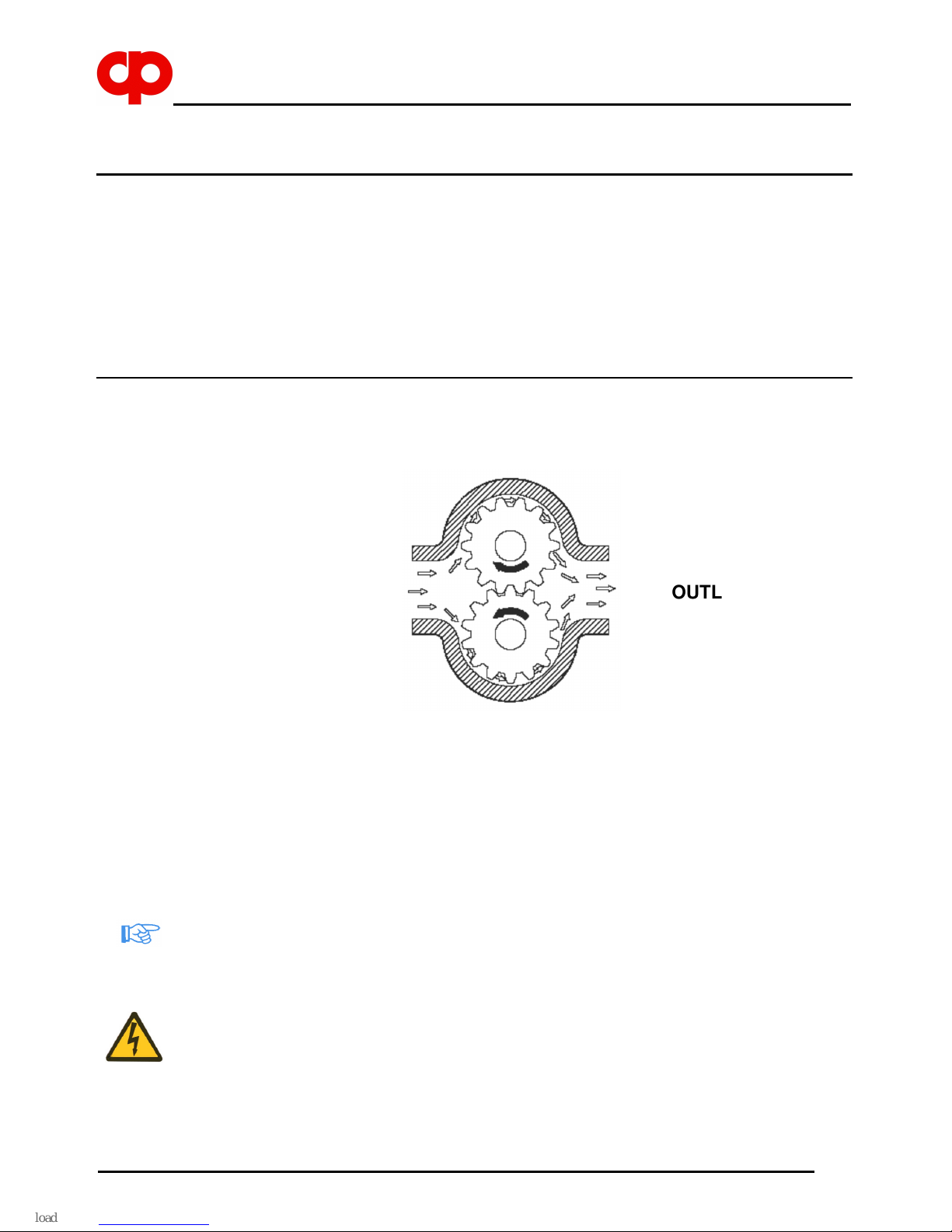
Essentially the pump consists of two driven pinions which mesh one another inside a cast
main body, thus creating a flow of liquid between the inlet and the outlet.
The fluid containment inside the pump is ensured by a suitable seal part as defined in the
order.
Pumps, series WPL are connected to the motor (shape B34), according to CE standards, by
means of a flexible (or magnetic) coupling and a bell housing, which also acts as safety
coupling guard.
The pump unit series WPL can be equipped with a mechanic reduction gear or a hydraulic
variator to adjust the rotation speed, according to CE standards.
3.2 WARNINGS
Standard construction pumps, as an indication, require a NPSH of approx. 0.4 bar. Always
calculate the maximum available suction lift, in relation to fluid characteristics, suction circuit
and operating conditions. Ensure that gears do not operate when dry. Before starting the
pump for the first time or after long stationary periods, it is advisable to fill the gear spaces
with oil or liquid being pumped through one of the nozzles and rotate the driving shaft by operating manually with a screwdriver on the motor cooling fan. This also makes it possible to
check for even and smooth movement of rotary components and excessive friction. It is recommended that an overland cut-out set at approx. 10% above the motor current be installed
in the control circuit.
INLET
OUTLET
Pompa ad Ingranaggi - Serie WPP, WPL
Gear Pump - WPP, WPL Series
28
In our pumps the direction of rotation is clearly shown by an arrow marking the right direction.
The pump operating temperature in normal working conditions is about 80°C. In special
pump versions, working temperatures of 180°C and more may be achieved. To protect personnel from dangers due to the temperatures reached during the operation of the machine,
in the event of accidental contact (burn), the User must reduce the external pump temperature by means of insulation plates, coatings, screens, barriers, etc. As limit reference temperature for the contact surface it is advisable to take 55°C. Below this value, for hot smooth
surfaces in bare metal, there is no burn threshold. For a detailed knowledge of this problem
in relation to different particular cases, the User can read the standard UNI EN 563 Ed.’94,
where burn thresholds are specified for several types of surface according to the “surface
temperature - contact time” parameters.
Liquids to be pumped must not contain abrasive or solid suspension as this will greatly reduce the pump life. At this purpose we recommend the installation of a properly sized filter
on the suction line if solids may be present.
When pumps are installed in parallel, the suction lines should be adequately separated to
prevent unnecessary turbulence.
3.3 PROTECTION DEVICE
The bell housing installed by the Manufacturer is made of an aluminium die-casting, fastened to the motor by screws, duly shaped to prevent fingers from coming into contact with
moving parts. It can be removed only by using a proper tool.
3.4 ADDITIONAL DESCRIPTION OF ACCESSORIES
3.4.1 Seal parts
The pump is usually supplied equipped with mechanical seal. If the Customer requires a
particular type of seal, Pompe Cucchi S.r.l. installs the desired seal after verifying if its dimensions are compatible with those of the pump. In case the Customer requires only the
seal mark, the Company leaves the Manufacturer to select the type of seal, by giving information about the pumped liquid.
3.4.2 Safety valve
The pump can be equipped with a safety valve, with adjustable calibration, installed on the
front of the pump body.
After reaching the calibration pressure, prevailing on the contrast spring reaction, the valve
starts opening by connecting the outlet side and the inlet side of the pump.
The valve function is just to protect the pump from accidental pressure peaks. Its prolonged
opening may imply the pump damaging.
Pompa ad Ingranaggi - Serie WPP, WPL
Gear Pump - WPP, WPL Series
29
4. INSTALLATION, ASSEMBLY
4.1 SPECIAL ASSEMBLY TOOLS
To assemble the pump you do not need special tools, except for seal extractors (see Maintenance).
4.2 INSTALLATION SITE INFORMATION
4.2.1 Space requirements for operation and installation
The space destined by the Customer to the installation of the machine should be enough to
gain access to, install and maintain the pump unit.
4.2.2 Inspection before starting installation
Before installation, the Customer must ensure that the environmental conditions of the selected site comply with requirements specified under the contract.
In particular, unless expressly required and accepted in the order, the installation site should
not be exposed to the following environmental conditions:
- abnormal temperature;
- high humidity;
- corrosive atmosphere;
- explosion and/or fire hazard areas;
- dust, sandstorms;
- earthquakes and other similar external conditions;
- high level of vibrations;
- high altitude;
- flood hazard areas.
4.2.3 Foundation details
When the pump unit is installed, it shall be firmly fixed in place by fastening bolts or by using
other securing methods.
Ground fastening bolts or other securing methods shall be of sufficient strength to prevent
the pump unit from moving accidentally.
4.2.4 Alignment requirements
The alignment operation must not submit the pump unit to axial and radial stress, therefore
the offset must always be lower than the tolerance limits expected for the coupling.
Particular attention should be paid to the alignment of the assemblies equipped with a magnetic coupling.
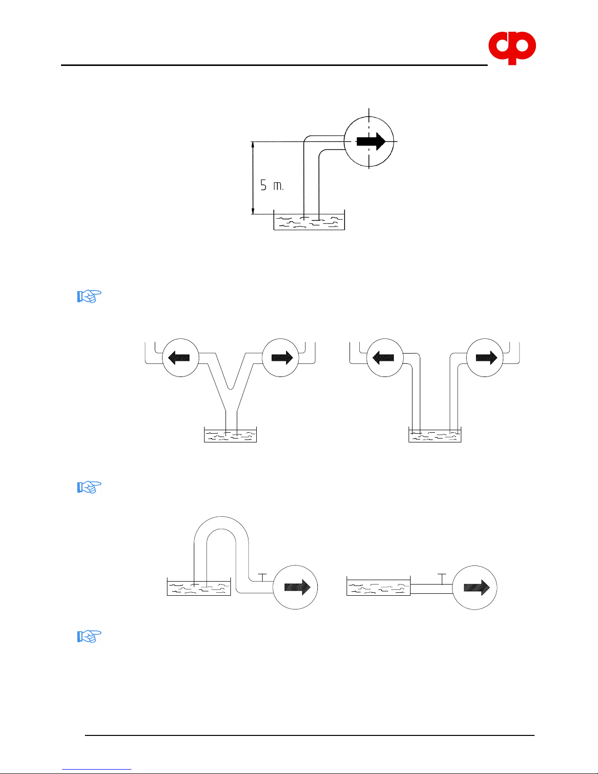
4.2.5 Suction lift
The suction lift, that is the vertical distance between the pump inlet mid-point and the free
surface of the tank to which the pump is attached, must not exceed 5 m to allow pump priming and avoid cavitation phenomena.
Pompa ad Ingranaggi - Serie WPP, WPL
Gear Pump - WPP, WPL Series
30
Otherwise, contact our Technical Department.
Each pump must have its own suction pipe; the installation of two or more pumps with a
common suction pipe length causes the pump to work less efficiently.
The length of the suction pipe must be reduced as much as possible to minimize pressure
losses in such segment; higher pressure losses in the discharge line do not adversely affect
the correct operation of the pump (if they do not exceed the delivery limits stamped on rating
plate).
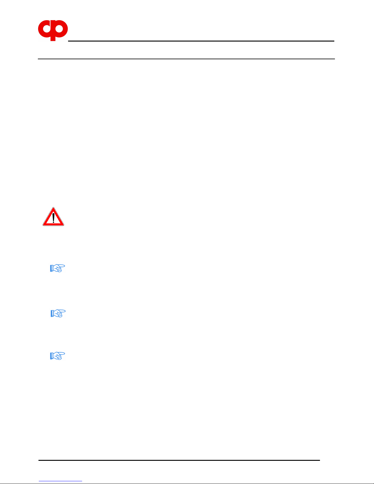
Furthermore, it is necessary to check that siphons are not created in the suction pipe, since
the formation of air pockets generates vibrations and stresses which are not compatible with
the correct operation of the pump and may obstruct the pump priming at startup.
In case of installation below head, the pump does not ensure to be able to intercept the flow
of fluid as a shut-off cock or a proper stop valve.
NO
YES
NO
YES
 Loading...