

Page 1
®
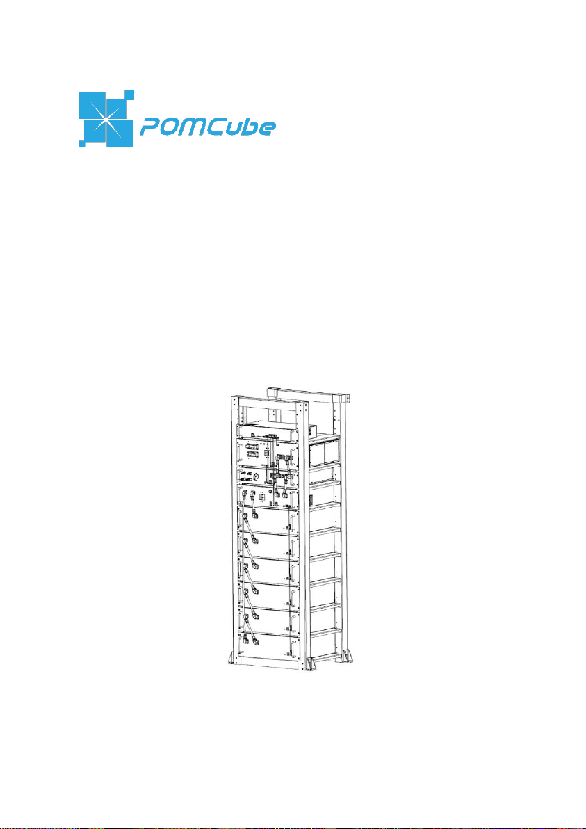
iCAN NetZero
User Manual
Intelligent Energy System
ICN1V1.0.4
Page 2

Page 3

Table of Contents
1. Preface ............................................................................. 1
2. Legal Compliance ........................................................... 2
2.1 Disposal and Recycling ................................................................... 2
2.2 FCC Statement ................................................................................ 2
3. Safety Instructions .......................................................... 3
3.1 Personal Safety ............................................................................... 3
3.2 Working Area Safety ........................................................................ 4
3.3 Cleaning and Maintenance .............................................................. 4
3.4 Warning Label .................................................................................. 5
4. About NetZero ................................................................. 5
4.1 Overview .......................................................................................... 5
4.2 Features .......................................................................................... 5
4.3 Specification .................................................................................... 6
4.4 Parts and Functions ......................................................................... 7
5. Installation ..................................................................... 16
5.1 Tools and Safety Gear ................................................................... 16
5.2 Assemble the Rack ................................ ........................................ 16
5.3 Install the Modules ......................................................................... 18
5.4 Internal Wiring ............................................................................... 19
5.5 External Wiring .............................................................................. 21
6. Basic Operations .......................................................... 24
6.1 Boot System .................................................................................. 24
6.2 Shut Down System ........................................................................ 24
6.3 Getting Started with NetZero App .................................................. 25
6.4 Network Connection ...................................................................... 25
6.5 Reset Network ............................................................................... 26
7. Troubleshooting ............................................................ 26
8. Emergency Situations .................................................. 28
9. Warranty and Service.................................................... 30
9.1 Limited Warranty ............................................................................ 30
9.2 Service ........................................................................................... 31
Page 4

1. Preface
Thank you for purchasing POMCube iCAN NetZero, an intelligent energy
system that helps provide a fully integrated power system for you. In order to
use your device safely, efficiently and effectively, please read the User
Manual thoroughly and follow the instructions provided before use. Please
keep this User Manual for future reference.
POMCube reserves the right to change products information and
specifications without notice. Products and specifications discussed herein
are for reference purposes only. All information discussed herein may change
without notice and without warranties of any kind. This document and all
information discussed herein remain the sole and exclusive property of
POMCube.
NetZero system may be updated for technical reasons without prior notice.
Purchasing this product indicates that you have acknowledged it and
accepted it.
Copyright© 2019 POMCube Inc. All rights reserved.
1
Page 5
2. Legal Compliance
2.1 Disposal and Recycling
This symbol on the product or on its packaging indicates
that this product must not be disposed of with your other
household waste. Instead, it is your responsibility to
dispose of your waste equipment by handing it over to a
designated collection point for the recycling of waste
electrical and electronic equipment. The separate collection and recycling of
your waste equipment at the time of disposal will help conserve natural
resources and ensure that it is recycled in a manner that protects human
health and the environment. For more information about where you can drop
off your waste equipment for recycling, please contact your local city office,
your household waste disposal service, or the shop where you purchased the
product.
2.2 FCC Statement
This device complies with Part 15 of the FCC Rules. Operation is subject to
the following two conditions:
(1) This device may not cause harmful interference, and
(2) This device must accept any interference received, including interference
that may cause undesired operation.
WARNING: Changes or modifications not expressly approved by the party
responsible for compliance could void the user’s authority to operate the
equipment.
NOTE: This equipment has been tested and found to comply with the limits
for a Class B digital device, pursuant to Part 15 of the FCC Rules. These
limits are designed to provide reasonable protection against harmful
interference in a residential installation. This equipment generates uses and
2
Page 6

can radiate radio frequency energy and, if not installed and used in
accordance with the instructions, may cause harmful interference to radio
communications. However, there is no guarantee that interference will not
occur in a particular installation. If this equipment does cause harmful
interference to radio or television reception, which can be determined by
turning the equipment off and on, the user is encouraged to try to correct the
interference by one or more of the following measures:
Reorient or relocate the receiving antenna.
Increase the separation between the equipment and receiver.
Connect the equipment into an outlet on a circuit different from that to which
the receiver is connected.
Consult the dealer or an experienced radio/TV technician for help.
RF Warning Statement
The device has been evaluated to meet general RF exposure requirement.
The device can be used in portable exposure condition without restriction.
3. Safety Instructions
WARNING: These safety instructions provide important safety information
and should be observed at all times. Please read them before using the
product.
3.1 Personal Safety
(1) This product is designed for indoor use only. Please keep it away from rain
or water. It is not suitable for use in damp rooms.
(2) Keep it away from children.
(3) Do not use the device if it is damaged or if it shows any kind of visible
damage.
(4) Do not handle the device and its components with wet hands. Failure to
observe this may result in electric shocks.
3
Page 7

(5) Do not dismantle the device.
(6) Do not damage any of the cable. Do not place it near any hot objects,
bend it excessively, twist it, pull it, or wrap it into a bundle.
(7) Shut down the device and switch off all the external input and output
switches from the home electrical panel for maintenance or extended
period of non-use.
(8) Always use genuine parts and accessories provided. Using parts and
accessories other than the provided one may cause short circuits or
overheating, and result in electric shock or fire.
3.2 Working Area Safety
(1) Always place the device on an even and stable surface to prevent it
tipping over.
(2) Do not place the device in a place which is not strong enough to take the
full weight of it.
(3) Keep the device away from direct sunlight or moisture.
(4) Keep the device away from heat sources, such as stovetops or ovens
(5) Do not subject the device to extreme temperatures.
(6) Do not subject the device to strong impact or vibration.
(7) Keep the device away from potentially dangerous location, such as
flammable, explosive, chemical-laden or wet atmospheres where petrol or
flammable liquids are used for stored
3.3 Cleaning and Maintenance
It is recommended that you clean the device by wiping it gently using a soft
and dry cloth. Do not use water, chemical substances or detergents. These
may cause discoloration or corrosion to the product's exterior, and may cause
a fire or electric shock.
Do not attempt to repair the device or its accessories by yourself, as damage
or personal injury may occur. Damage caused by unauthorized repair is not
4
Page 8

under the warranty. Please contact your local distributor for any possible
problems concerned with the product.
3.4 Warning Label
Please pay attention to the warning label and follow the instruction
mentioned.
POMCube disclaims all liability for any accidents or damage caused by using
the product in the ways that are not described in this User Manual or using
non-genuine parts or accessories.
4. About NetZero
4.1 Overview
iCAN NetZero relieves zero net energy homeowners from their daily chore in
managing battery and selecting the source of energy repeatedly. NetZero
automatically selects the most economical, reliable and sustainable energy
while keeping the system running 24/7 without human intervention. The
ultimate goal for NetZero is to eliminate the reliance of conventional power
produced from fossil energy and maximize the use of clean energy, whether
they are locally generated or from the grid.
4.2 Features
(1) Automated Operation
NetZero can control its built-in batteries, your solar and generator to maximize
the efficiency of your power system. All are performed automatically.
(2) Easy Installation
NetZero is designed in modular and therefore it is easy to install.
(3) Maintenance Free
The lithium batteries are maintenance free with the BMS (Battery
5
Page 9
Model No.
PNZ-BBS1
Battery Quantity
4 5 6
AC1 (Grid)
90-140Vac, 50/60±5Hz, Max. 63A
AC2 (Generator)
AC Load
5.0kVA, 50/60Hz, 110/120/127Vac
Overload Cap.:120% >3s, 150% >0.15s
Solar Controller
Input Voltage: 200-650Vdc
Max. Input Power: 6.6kW
Max. Charge Power: 5.0kW
MPPT Voltage
245-550Vdc
300-550Vdc
360-550Vdc
Capacity
(100%)*1
44.8V90Ah
16.1kWh
20.2kWh
24.2kWh
51.2V90Ah
18.4kWh
23.0kWh
27.6kWh
Dimension
H*W*D: 1750*570*520mm / 70*22.5*20.5in
Weight*2
265Kg/585lbs
313Kg/690lbs
360Kg/795lbs
Operating
Environment
Temperature: 41-104°F/5-40°C
Humidity: 10%-90% (No Condensation)
Origin
China
Management System) built-in.
(4) Multiple Working Modes
NetZero supports both on-grid and off-grid power systems.
(5) App Monitoring
You can monitor and control your NetZero anywhere by using the app.
(6) Intelligent Learning
NetZero is able to improve the strategy for you based on the learning of your
daily energy usage.
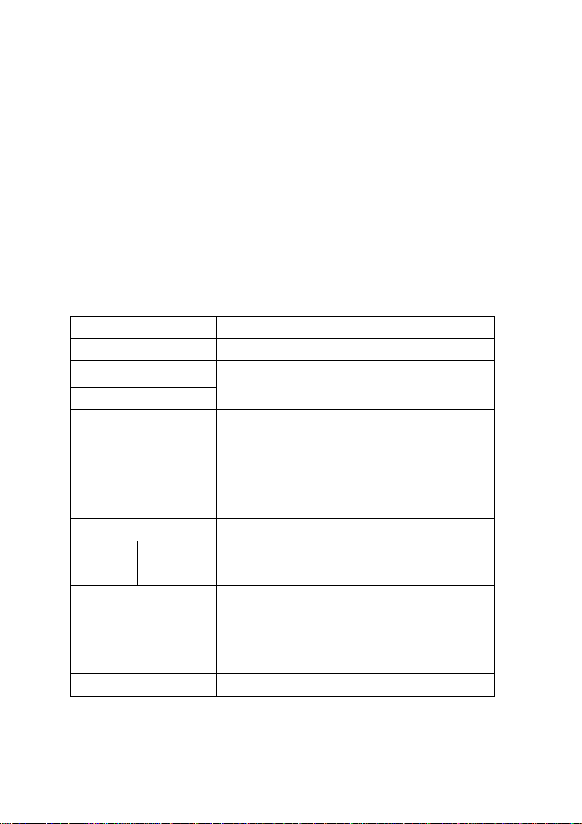
4.3 Specification
Table 4.3.1: Specification
6
Page 10
NOTE:
1. The actual battery DoD (Depth of Discharge) is at 80%.
2. Slight weight deviation for each device.
3. V
@NOCT (Nominal Operating Cell Temperature)of solar panel string
mpp
should be greater than the minimum voltage of MPPT voltage. Refer to solar
panel specification for the data of V
at NOCT condition.
mpp
4.4 Parts and Functions
NOTE: The images shown in this User Manual are for reference only and may
slightly differ from the actual product, and the actual product appearance
depends on your option.
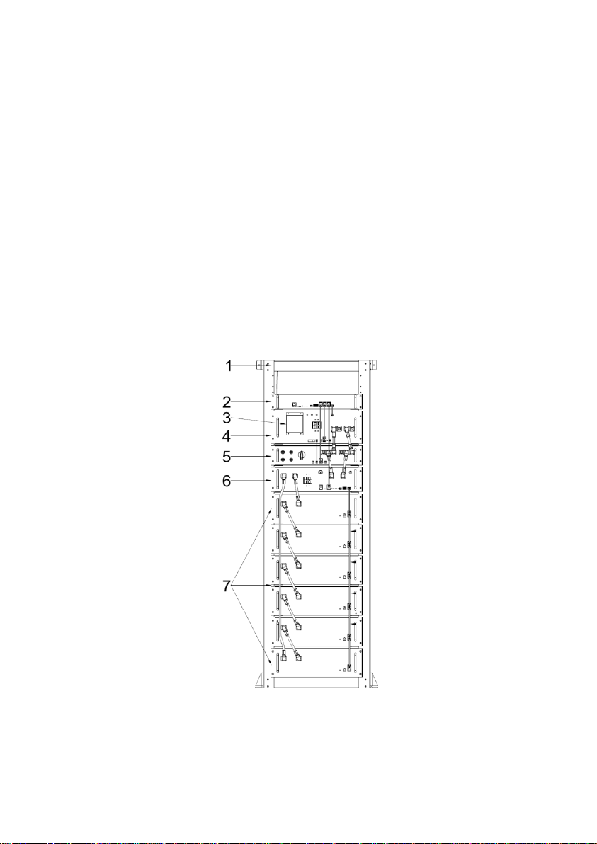
(1) Top-level
Figure 4.4.1: NetZero Front View
7
Page 11
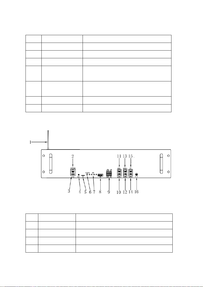
No.
Parts
Functions
1
Rack
Mechanical support.
2
EMS Module
Manage the whole system.
3
Protection Cover
Protect the AC input/output connector.
4
PCSModule
Convert the power from AC to DC or from
DC to AC.
5
Solar Controller
Track the Max. Power Point of solar power,
charge the battery, power the load.
6
BCMS Module
Manage and protect all battery modules.
7
BatteryModule
Store electric energy.
(2) EMS Module
No.
Parts
Functions
1
Wi-Fi Antenna
Enhance Wi-Fi signal.
2
NETWORK
RJ45 port, connect to the router/Internet.
3
USB
USB flash drive for storage of operation data.
4
RST
Wi-Fi reset button.
Table 4.4.1: Top-level Parts
Figure 4.4.2: EMS Front View
Table 4.4.2: EMS Parts
8
Page 12
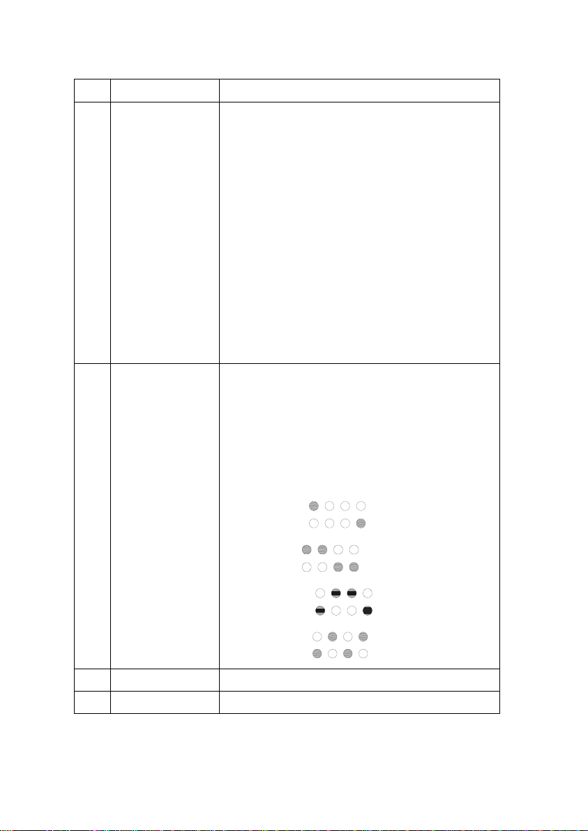
5
SD
SD card for storage of operation data.
6
STATUS
Indicate the device status and the network
status:
Solid red: System startup in progress.
Blinking red: Ready for network connection.
Blinking green: Wi-Fi network and password
detected; connecting to router. If it blinks for
over 3 minutes, either the network or the
password might be incorrect.
Solid white: Connecting to the Internet or
troubles in Internet connection while the router
connection works properly.
Solid green: Internet connected successfully.
7
SOC
Indicate real-time battery capacity: Each light
represent 25% capacity. The lights blink in
sequence under system charging and
discharging.
Blinking indicate the communication timeout as
below:
EMS module:
PCS module:
Solar controller:
BCMS module:
8
ADD
The communication address of EMS module.
9
Dry Contact
NC1&COM1: Stop generator.
9
Page 13
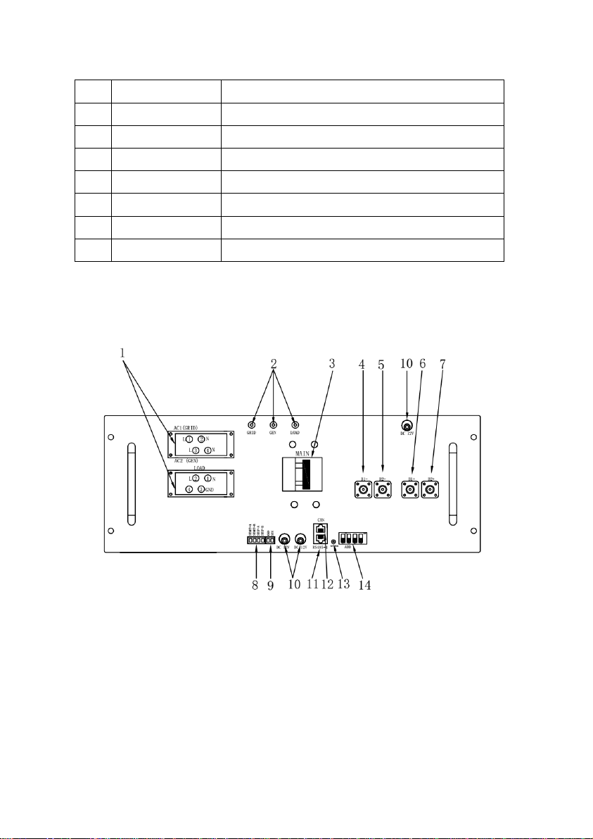
Others: Reserved.
10
RS485-2
Communicate with solar controller.
11
RS232
For the manufacturer’s debugging.
12
RS485-3
Communicate with PCS module.
13
RS485-4
Reserved, RJ45 port, follow RS485 protocol.
14
RS485-1
Reserved, RJ45 port, follow RS485 protocol.
15
CAN
Communicate with BCMS module.
16
DC-12V
DC12V power supply input.
NOTE: Either the USB flash drive or the SD card is provided to the device.
Removing it will cause the operation data lost.
(3) PCS Module
Figure 4.4.3: PCS Front View
10
Page 14
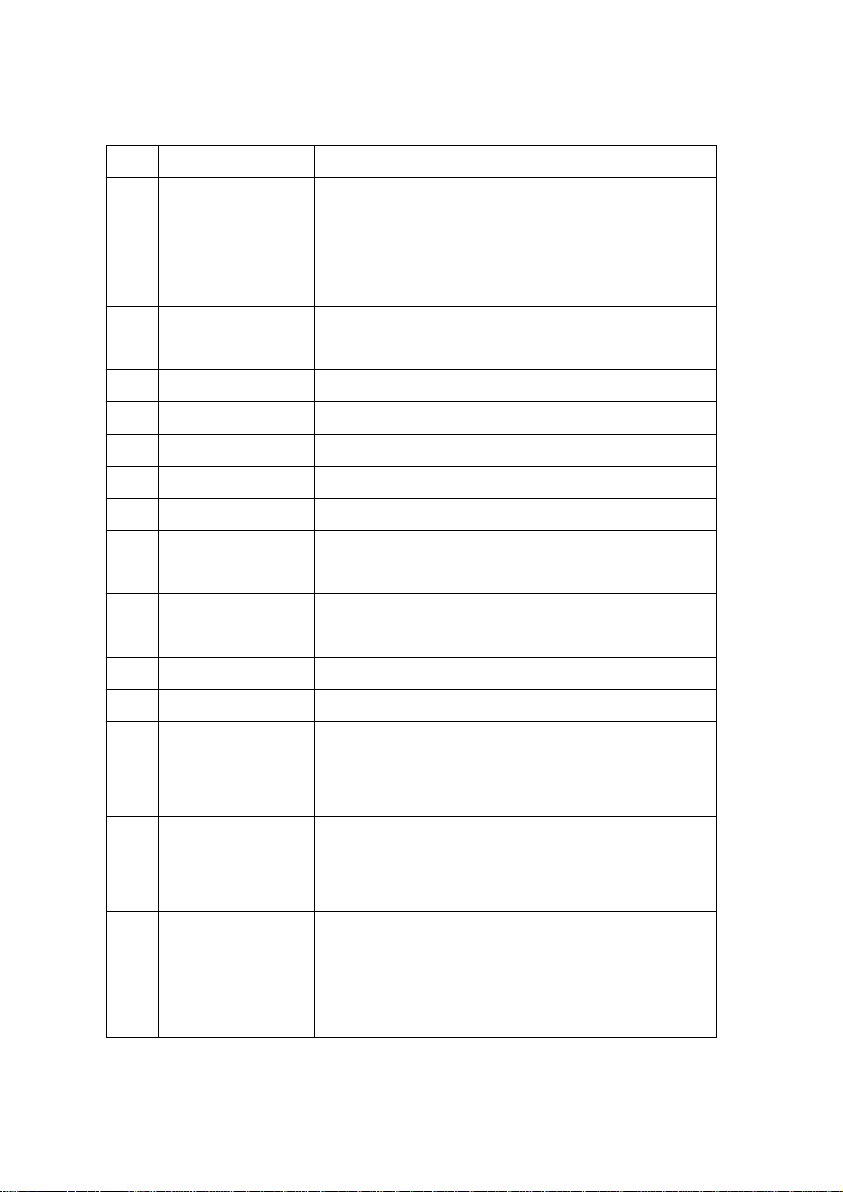
No.
Parts
Functions
1
AC Input /
Output
AC1 (GRID): Grid input.
AC2 (GEN): Generator input.
LOAD: Load output.
GND: Safety ground.
2
Power Supply
Status
On: Power supply is normal.
Off: No power.
3
MAIN
Load output switch.
4
B1-
Battery bus negative (-)#1.
5
B2-
Battery bus negative (-)#2.
6
B1+
Battery bus positive (+)#1.
7
B2+
Battery bus positive (+)#2.
8
Generator Start
and Stop
START-A&START-B: Start generator.
STOP-A&STOP-B: Stop generator.
9
Synchronizing
Signal
SYN&GND, for communication between two
NetZeroes-
10
DC-12V
DC12V power supply output.
11
RS485
Communicate with EMS module.
12
CAN
Communicate with other PCS modules, two
NetZeroes applied as split phase synchronize in
the signal interface.
13
STATUS
Indicate the power status of PCS module:
On: Power supply is normal.
Off: No power.
14
ADD
The communication address of PCS module.
If two NetZero are applied as split phase,
please set the 4 ADD switches accordingly:
#1 PCS: set ADD 1 down, ADD 2, 3, 4 up;
Table 4.4.3: PCS Parts
11
Page 15
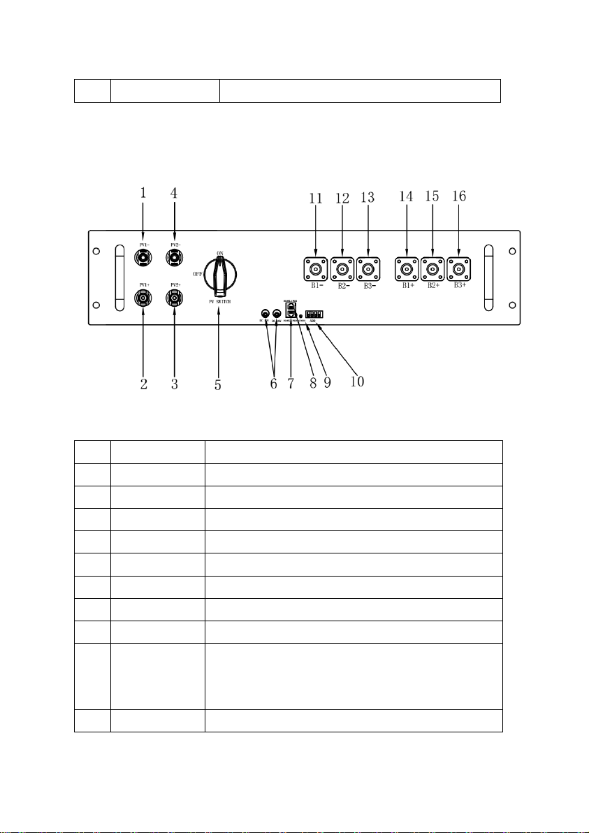
#2 PCS: set ADD 2 down, ADD 1, 3, 4up.
No.
Parts
Functions
1
PV1-
Solar power input negative (-) #1.
2
PV1+
Solar power input positive (+) #1.
3
PV2+
Solar power input positive (+) #2.
4
PV2-
Solar power input negative (-) #2.
5
PV SWITCH
Solar power input switch.
6
DC-12V
DC12V power supply output.
7
RS485-LINK2
Communicate with other solar controller.
8
RS485-LINK1
Communicate with EMS module.
9
STATUS
Indicate the power status of PV module:
On: Power supply is normal.
Off: No power.
10
ADD
The communication address of solar controller.
NOTE: Either the USB flash drive or the SD card is provided to the device.
Removing it will cause the operation data lost.
(4) Solar Controller
Figure 4.4.4: Solar Controller Front View
Table 4.4.4: Solar Controller Parts
12
Page 16
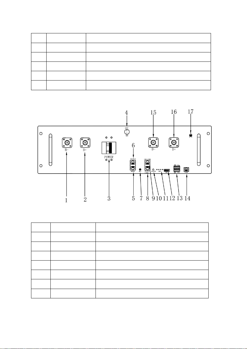
11
B1-
Battery bus negative (-) #1.
12
B2-
Battery bus negative (-) #2.
13
B3-
Battery bus negative (-) #3.
14
B1+
Battery bus positive (+) #1.
15
B2+
Battery bus positive (+) #2.
16
B3+
Battery bus positive (+) #3.
(5) BCMS Module
No.
Parts
Functions
1
B-
Battery bus positive (-).
2
B+
Battery bus negative (+).
3
POWER
Power switch.
4
Power Switch
Reserved.
5
RS232
For the manufacturer’s debugging.
6
RS485-2
Reserved, RJ45 port, follow RS485 protocol.
7
RST
Reset BCMS module.
Figure 4.4.5: BCMS Front View
Table 4.4.5: BCMS Parts
13
Page 17
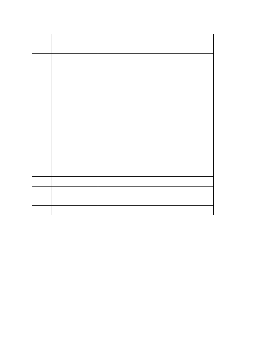
8
RS485-1 LINK2
Communicate with other BCMS module.
9
CAN-LINK1
Communicate with EMS module.
10
STATUS
Indicate BCMS module status:
Blinking blue: Boot up in progress;
Blinking green: Self-inspecting;
Solid green: Working normally;
Solid pink: Alarming
Solid red: In device protection or troubles.
11
SOC
Indicate real time battery capacity: Each light
represents 25% capacity. The lights blink in
sequence under system charging and
discharging.
12
ADD
The communication address of BCMS
module.
13
Dry Contact
Reserved. Four output and two input.
14
LINK
Communicate with battery module.
15
D+
DC bus positive (+).
16
D-
DC bus negative (-).
17
DC-12V
DC12V power supply output.
14
Page 18
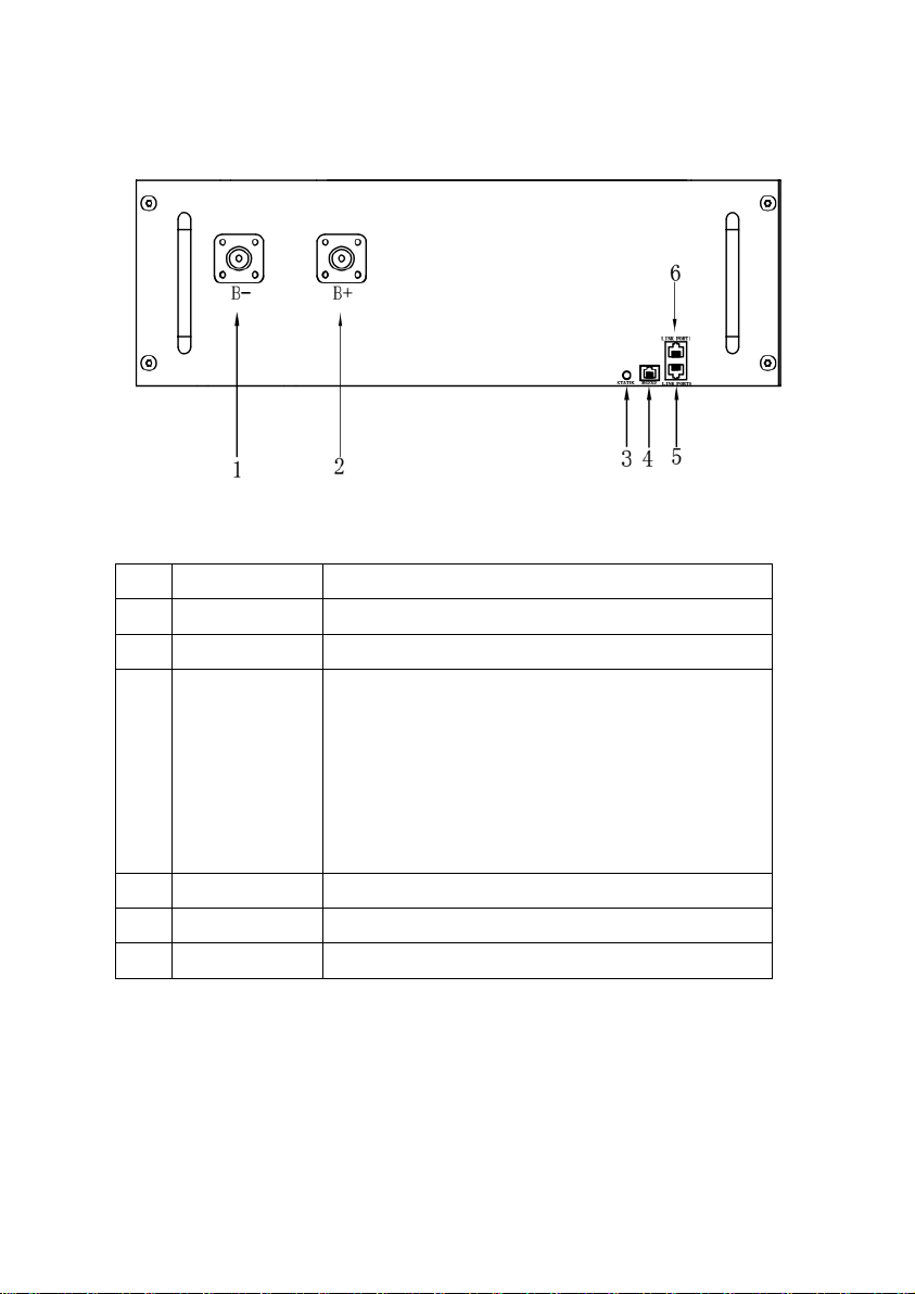
(6) Battery Module
No.
Parts
Functions
1
B-
Battery module positive (-).
2
B+
Battery module negative (+).
3
STATUS
Indicate battery module status:
Blinking yellow: Bootup in progress;
Blinking blue: Self-inspecting;
Solid green: Working normally;
Solid pink: Alarming;
Solid red: In device protection or troubles.
4
RS232
For the manufacturer’s debugging.
5
LINK PORT0
Communicate with battery module.
6
LINK PORT1
Communicate with battery or BCMS module.
Figure 4.4.6: Battery Front View
Table 4.4.6: Battery Parts
15
Page 19
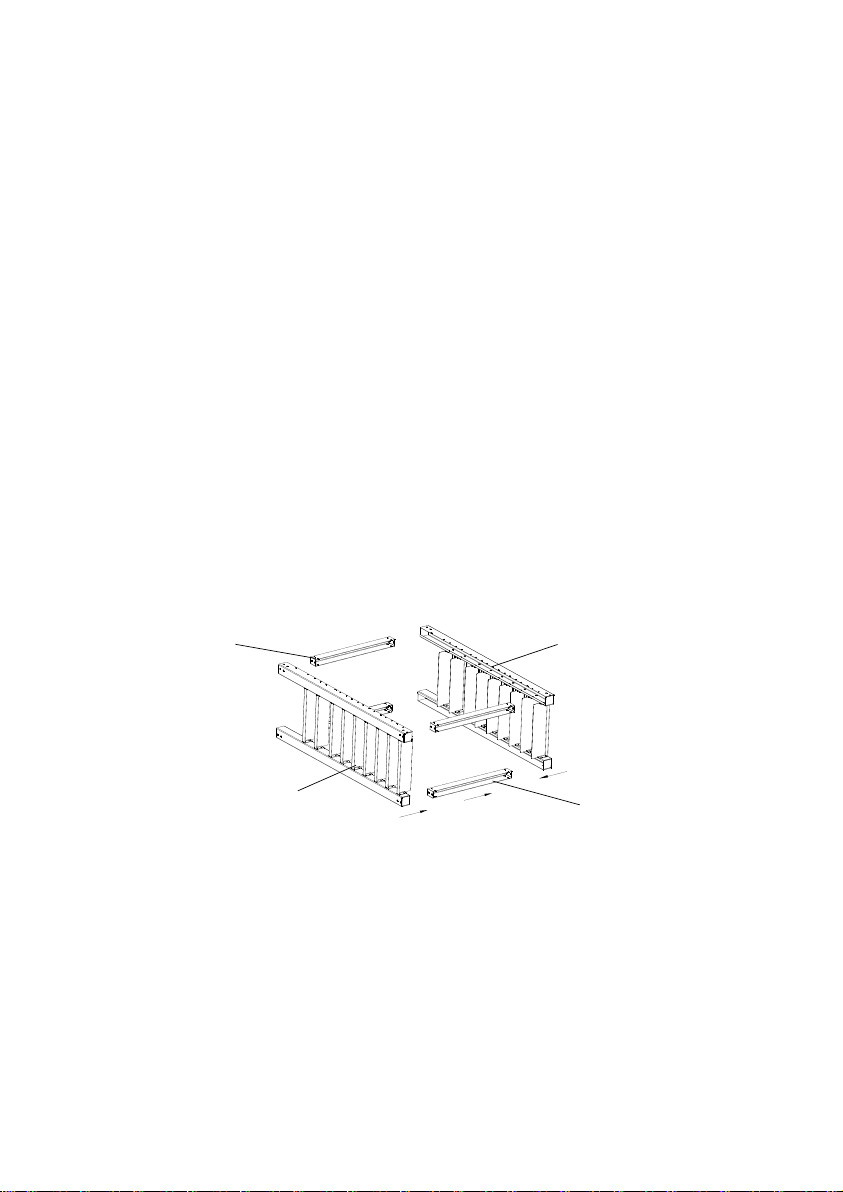
Beam
4pcs
Left Side Frame
Right Side Frame
Opening Side
of the Beams
5. Installation
5.1 Tools and Safety Gear
NOTE: It is recommended to use proper tools and wear safety gears when
installing.
(1) Slotted Screw Driver
(2) 4mm Inner Hexagonal Screw Driver
(3) Wire Cutter
(4) Insulated Gloves
(5) Safety Goggles
(6) Safety Shoes
5.2 Assemble the Rack
(1) Put the frames and beams together as the figure shown. Pay attention to
the directions of the opening side of beams.
(2) Install the screws to fasten the frames and beams.
Figure 5.2.1: Put the Frames and Beams Together
16
Page 20
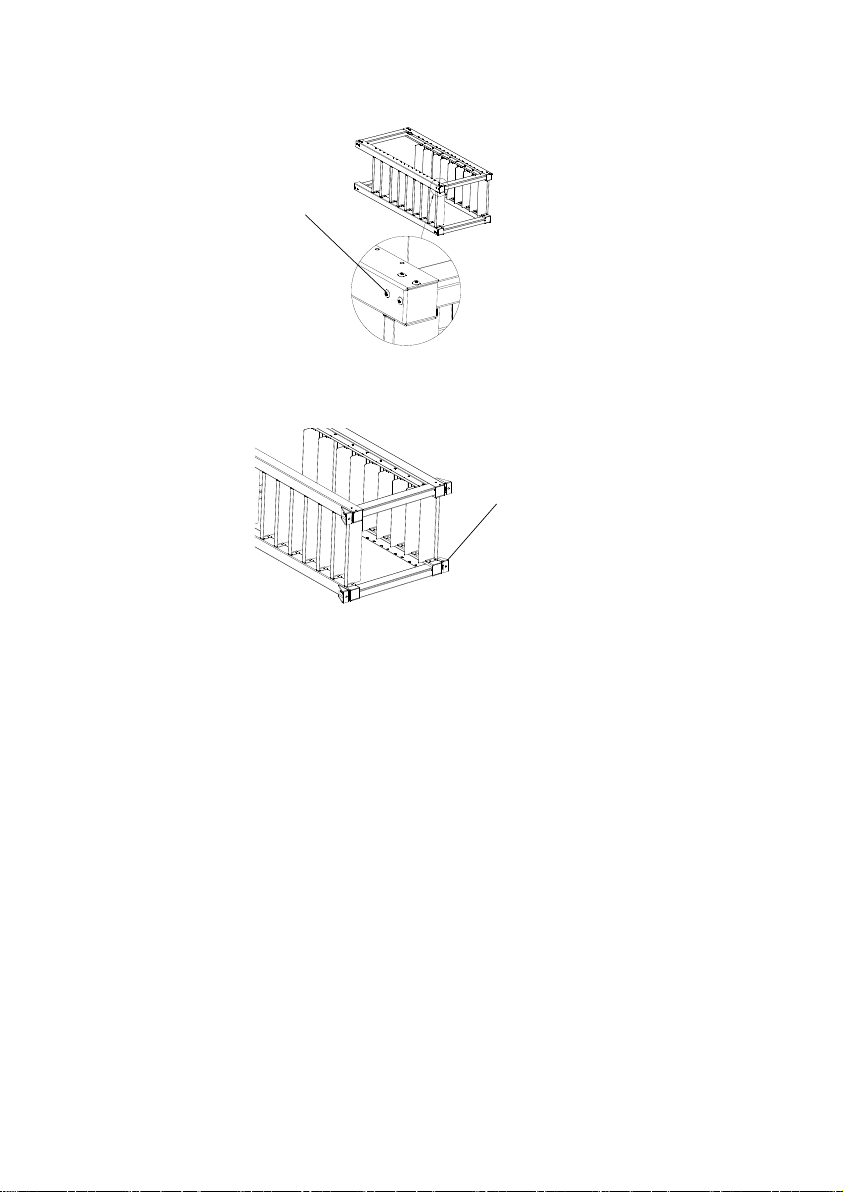
Screw M5*8
32pcs
Floor Mounting Part
4pcs
Screw M8*25
4pcs
Figure 5.2.2: Install the Screws
(3) Fasten the floor mounting part with screw.
Figure 5.2.3: Fasten the Floor Mounting Part
(4) Put the rack where NetZero will be placed and mount it to the floor and
wall with anchor bolts if necessary.Make sure the rack is horizontal and
the front side faces forward. Pay attention to the maintenance space
requirement for each side.
17
Page 21
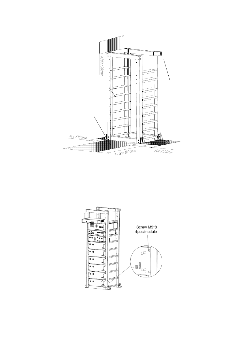
Front Side is with Threaded
Holes on the Support Surface
Maintenance Space
Wall Mounting
Part, 2pcs
Figure 5.2.4: Place and Mount the Rack
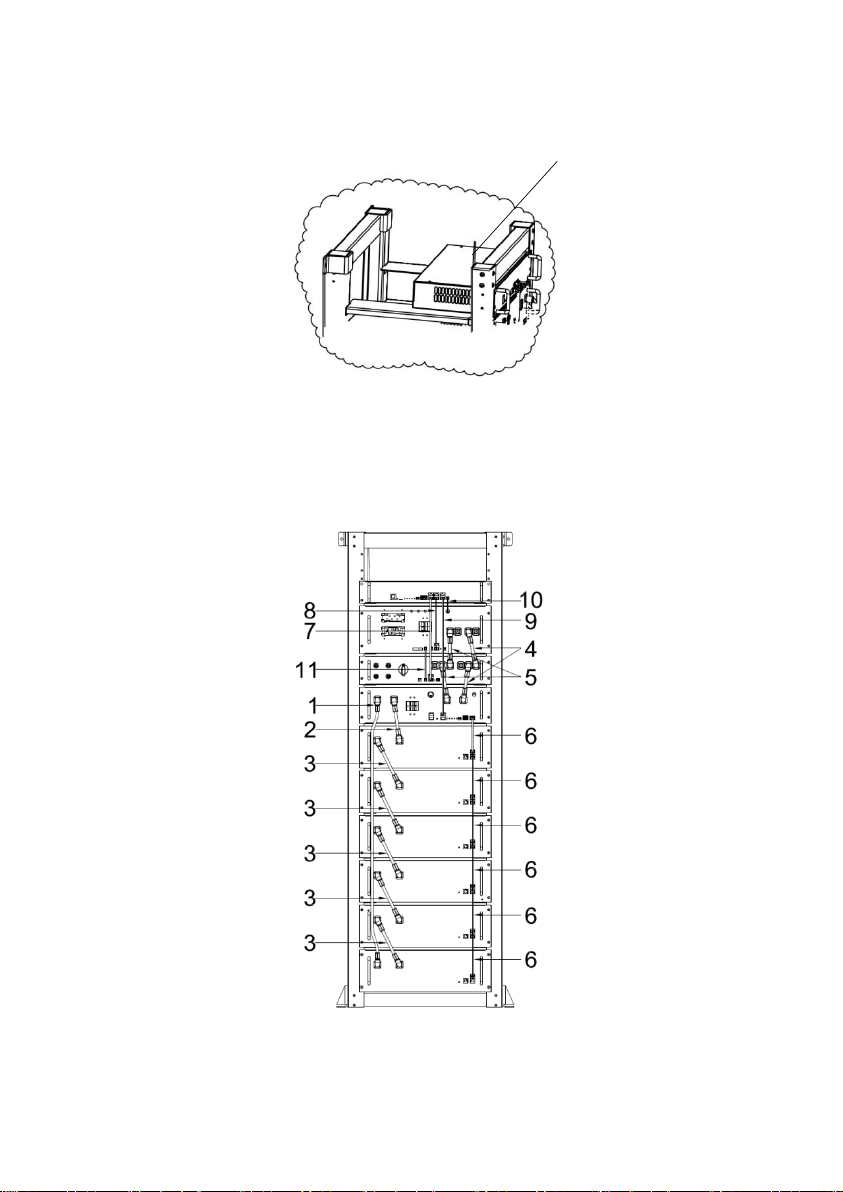
5.3 Install the Modules
(1) Put all the modules into the rack from the front side and then fasten them
with screws.
Figure 5.3.1: Install the Modules
18
Page 22
Wi-Fi Antenna
(2) Screw the Wi-Fi Antenna onto the connector as the figure shown.
Figure 5.3.2: Screw on the Wi-Fi Antenna
5.4 Internal Wiring
Connect the cables between the modules as the figure shown.
Figure 5.4.1: Internal Wiring Diagram
19
Page 23

No.
Cable Specifaction
Connection
1
Power cable / Black /
1500mm/ 4AWG / 2 black
Surlok connectors
The bottom battery module B- to
BCMS module B-.
2
Power cable / Orange /
160mm/ 4AWG /2 orange
Surlok connectors
The top battery module B+
to BCMS module B+
3
Power cable / Orange /
190mm/ 4AWG / 1
orange & 1 black Surlok
connectors
Battery module B- to the next battery
module B+ below.
4
Power cable / Orange /
130mm/ 4AWG /2 orange
Surlok connectors
Solar controller B2+ to PCS B1+.
Solar controller B1+ to BCMS D+.
5
Power cable / Black /
130mm/ 4AWG /2
Black Surlok connectors
Solar controller B2- to PCS B1-.
Solar controller B1- to BCMS D-.
6
Communication cable /
Black / 190mm / Standard
8 way Ethernet cable/
RJ45 connectors
BCMS module Link Port to the top
battery module Link Port 0.
Battery module Link Port 1 to the next
battery module Link Port0 below.
7
Communication cable /
Black / 440mm / Standard
8 way Ethernet cable/
RJ45 connectors
EMS module RS485-2 to solar
controller RS485-LINK1
8
Communication cable /
Black / 350mm / Standard
8 way Ethernet
EMS module RS485-3 to
PCS module RS485-2
Table 5.4.1: Cable List
20
Page 24
cable/RJ45 connectors
9
Communication cable /
Black / 620mm / Standard
8 way Ethernet cable/
RJ45 connectors
EMS module CAN to BCMS module
CAN
10
DC 12V Power
cable/150mm
PCS module DC12V to
EMS module DC12V.
11
DC 12V Power
cable/120mm
PCS module DC12V to
Solar controller DC12V.
NOTE: Keep pressing the lock button when unplug the Surlok connector.
WARNING: Failure to follow the instructions may damage the device.
5.5 External Wiring
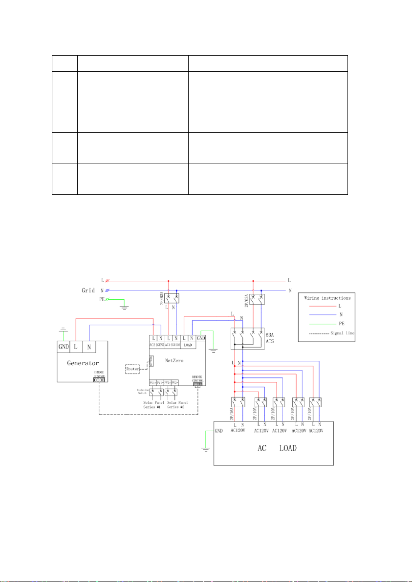
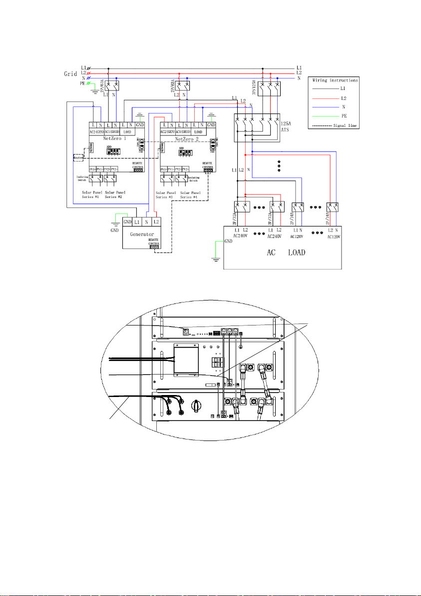
(1) Connect the external cables as the figures shown.
Figure 5.5.1: Single Phase Example Wiring Diagram
21
Page 25
Solar Power Wire
Communication Wire
Figure 5.5.2: Split Phase Example Wiring Diagram
WARNING: Generator must be turned off and switch to “non-remote” mode
before refueling. Failure to follow this instruction may cause fire and
explosion.
Figure 5.5.3: Example Wire Routing
22
Page 26
NOTE:
Set the ADD address for both NetZero PCS under split phase application.
Refer to PCS Module part of this instruction for more details.
All external ports should be equipped with switches.
The National Electric Codes (NEC), local codes, and similar standards
outline detailed requirements for safe installation of electrical equipment.
Installation must comply with specifications for wire types, conductor sizes,
electrical and thermal insulation, branch circuit protection, grounding, and
disconnect devices.
The actual connection depends on your application case. Not all the ports
are necessary to be connected.
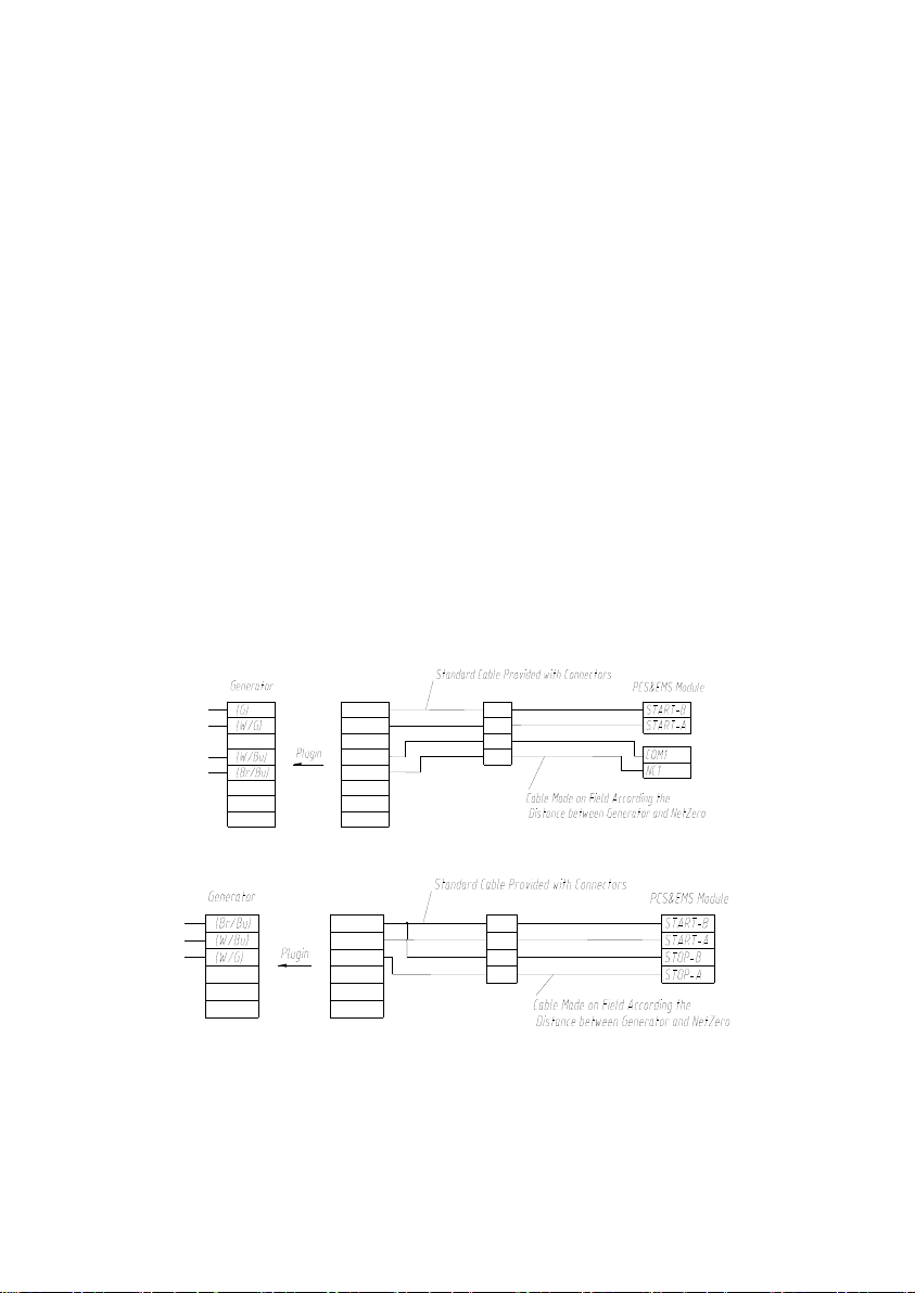
Please set up the actual value of generator maximum power by the app.
Refer to the generator user manual for the detail information about how to
install/connect the remote control cable and how to switch the generator
into remote mode. Figures below are examples for typical generators
remote cable connection.
Figure 5.5.4: Remote Connection for Honda EU7000iS
Figure 5.5.5: Remote Connection for Honda EM7000iS, EU6500iS,
EM6500SXK1/K2, EM5000SXK2/K3, EM5000iS, EM4000SX&EM3800SX
(2) Refer to the table below for minimum copper wire sizing and ratings.
23
Page 27

AC
Solar
Enternet
Voltage Rating
600V
1000V
30V
Temp. Class
75°C
75°C
60°C
Gauge
6AWG
12AWG
Standard Ethernet cable
Table 5.5.2: Minimum Copper Wire Sizing and Ratings
6. Basic Operations
6.1 Boot System
(1) Switch on the Power switch on the BCMS module, wait 60 seconds until
(Usually it takes 45 seconds for the 8 battery modules to be fully started
up; the more battery modules utilized, the longer the startup process takes.
For every battery module added, it takes 3.5 seconds longer to startup.
Therefore, it takes more than 60 seconds for 12 battery packs to be fully
started up.) the BCMS and Battery Module start normally, and
(2) Switch on the PV SWITCH on the Solar Controller, and
(3) Switch on the MAIN switch on PCS&EMS module.
WARNING: Failure to follow the instructions may damage the device.
6.2 ShutDown System
(1) Switch off the MAIN switch on PCS module, and
(2) Switch off the PV switch on the Solar Controller, and
(3) Switch off the POWER switch on the BCMS module.
WARNING:
Failure to follow the instructions may damage the device.
Shut down the device and switch off all the external switches from the home
electrical panel for maintenance or extended period of non-use.
24
Page 28
6.3 Getting Started with NetZero App
NOTE: The app is not necessary for NetZero. But it is recommended to use
the app if you want to monitor your NetZero better.
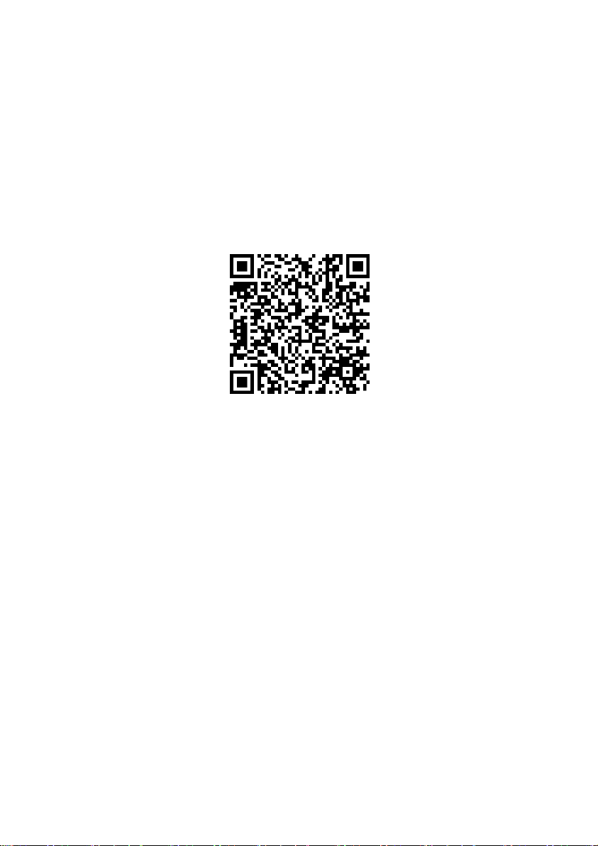
(1) Download the App
You can scan the QR code below to download Eloncity app, or scan the QR
code on the packing box to download it, or search and download it from Apple
App Store.
Figure 6.4.1: iOS
Eloncity
(2) Add New Devices
Start Eloncity app and touch the add device button, then scan the device QR
code or input the device code to add your devices. You can find the QR code
and the device code on the label pasted on the device.
App
6.4 Network Connection
NOTE: The network is not necessary for NetZero. But NetZero should be
connected to your router if you need to use the app to monitor it. Internet is
required only if you want to monitor NetZero when you are not at home.
NetZero can be connected to the router/Internet through an active Ethernet
Cable or Wi-Fi. Please follow the instructions in the app to complete the
connection.
(1) Ethernet Cable Network Connection
Insert an active Ethernet Cable into the RJ45 port of the device. Select
25
Page 29
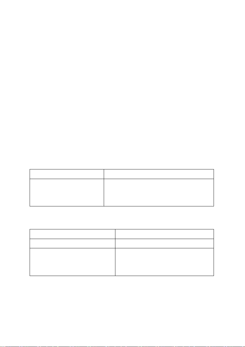
Possible Reasons
Solutions
The device may be crashed
or damaged.
Unplug power supply of DV12 on EMS and
re-plug in 5 seconds. If it cannot recover,
shut it down and contact us.
Possible Reasons
Solutions
The Wi-Fi is not 2.4G.
Select a 2.4G Wi-Fi.
The indicator was not blinking red
before configuring the network.
Make sure the indicator is blinking red
before configuring the network.
Try to re-configure the network.
“Ethernet Cable” in the Network Connection interface of the app.
(2) Wi-Fi Connection
Select “Wi-Fi” in the Network Connection interface of the app.
NOTE: NetZero only supports 2.4G Wi-Fi.
6.5 Reset Network
Long press RST button for 4 seconds on EMS module. Please re-configure
the network following the instructions in the app.
NOTE: A small rod may be needed to press the Reset Button. It is not
provided.
7. Troubleshooting
(1) The indicators on EMS modules are always solid red.
Table 7.1: Solutions for Troubles #1
(2) The indicators on EMS modules are always blinking red.
Table 7.2: Solutions for Troubles #2
(3) The indicators on EMS modules are always blinking green.
26
Page 30
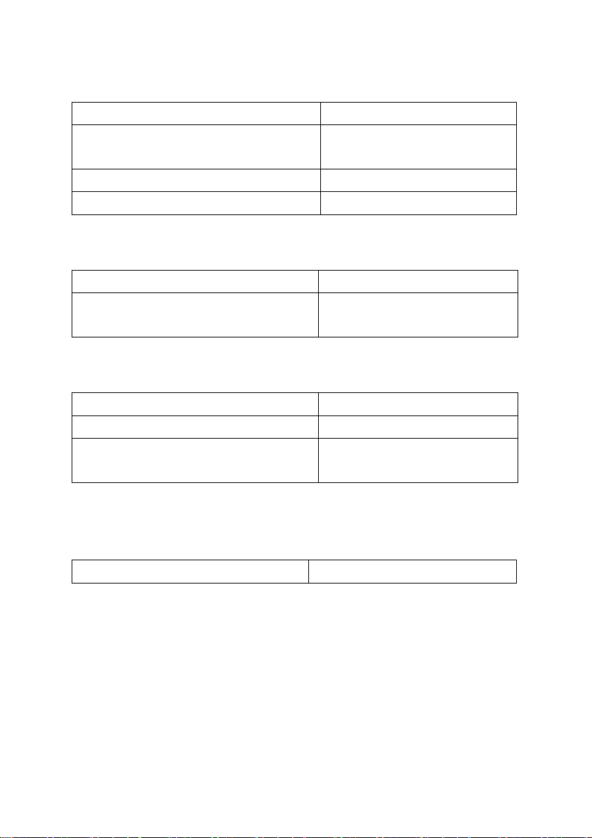
Possible Reasons
Solutions
The router may not work properly.
Check the router status. Reset
the router if necessary.
The Wi-Fi password put in was incorrect.
Try to re-configure the network.
Wi-Fi was changed.
Re-configure the network.
Possible Reasons
Solutions
Something wrong with the router or
Internet.
Check your internet status.
Reset the router if necessary.
Possible Reasons
Solutions
The generator may not work properly.
Check the generator.
The remote control cable is
disconnected.
Check and re-connect the cable.
Possible Reasons
Solutions
Table 7.3: Solutions for Troubles #3
(4) The indicators on EMS modules are always solid white.
Table 7.4: Solutions for Troubles #4
(5) Failed to start the generator remotely.
Table 7.5: Solutions for Troubles #5
(6) The indicator on BCMS module is solid red and the indicator on at least
one battery module is solid red.
Table 7.6: Solutions for Troubles #6
27
Page 31

The system
is in the
most critical
level
protection
mode.
Step 1: Charge BCMS. If it is successfully charged, the
indicator on SOC will blink.
Step 2: If battery charge in Step 1 doesn’t work in 5 minutes,
shut down and reboot BCMS following the procedures in
Chapter 6.2 - ShutDown System then Chapter 6.1 - Boot
System.
Step 3: If neither steps above is successful, contact us.
The battery
module may
be dead.
Contact us.
Possible Reasons
Solutions
The communication cable between BCMS and
the battery module may be disconnected.
Check and re-connect the
cable.
Follow the procedures in
Chapter 6.2 - ShutDown
System then Chapter 6.1 Boot System to shut down
and reboot BCMS.
Possible Reasons
Solutions
Voltage shortage of battery.
Charge the batteries immediately.
(7) The indicator on BCMS module is solid red and the indicator on every
battery module is solid green.
Table 7.7: Solutions for Troubles #7
(8)
The indicator on BCMS module is solid red, and the indicator on one
battery module is solid pink or off.
Table 7.8: Solutions for Troubles #8
NOTE: When the indicator on BCMS is solid red, and the status indicator on
battery module is solid pink or off, reboot BCMS. After reboot is finished (or
wait 1min), the indicator on the battery module will be solid red then off; and
28
Page 32
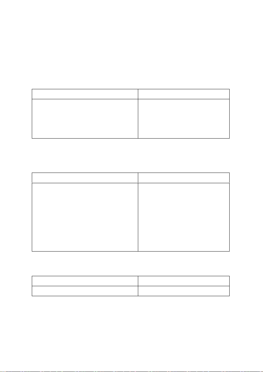
Possible Reasons
Solutions
BCMS fails in self-inspection.
Follow the procedures in Chapter
6.2 - ShutDown System then
Chapter 6.1 - Boot System to shut
down and reboot BCMS.
Possible Reasons
Solutions
Failure in CAN communication.
Step 1: Reconnect CAN
communication line between
BCMS and battery module.
Step 2: Follow the procedures in
Chapter 6.2 - ShutDown System
then Chapter 6.1 - Boot System to
shut down and reboot BCMS.
Possible Reasons
Solutions
Low battery.
Charge the battery.
the indicators on the battery modules will be also off sequently. This indicates
the batteries are suspended from voltage shortage. Charge the batteries
immediately.
(9) The indicator on BCMS keeps blinking in green for over 1 minute.
Table 7.9: Solutions for Troubles #9
(10) The indicator on battery module keeps blinking in blue for over 30
seconds.
Table 7.10: Solutions for Troubles #10
(11) The indicator on BCMS or battery module is pink while SOC is 0.
8. Emergency Situations
Table 7.11: Solutions for Troubles #11
29
Page 33

(1) Leaking Batteries
If the battery pack leaks electrolyte, avoid contact with the leaking liquid or
gas. If one is exposed to the leaked substance, immediately perform the
actions described below.
Inhalation: Evacuate the contaminated area, and seek medical attention.
Contact with eyes: Rinse eyes with flowing water for 15 minutes, and seek
medical attention.
Contact with skin: Wash the affected area thoroughly with soap and water,
and seek medical attention.
Ingestion: Induce vomiting, and seek medical attention.
(2) Fire
NO WATER! Only dry powder fire extinguisher can be used; if possible, move
the battery pack to a safe area before it catches fire.
(3) Wet Batteries
If the battery pack is wet or submerged in water, do not let people access it,
and then contact POMCube or an authorized dealer for technical support.
(4) Damaged Batteries
Damaged batteries are dangerous and must be handled with the utmost care.
They are not fit for use and may pose a danger to people or property. If the
battery pack seems to be damaged, pack it in its original container, and then
return it to POMCube or an authorized dealer.
NOTE: Damaged batteries may leak electrolyte or produce flammable gas. If
such damage occurs, please contact POMCube.
9. Warranty and Service
9.1 Limited Warranty
Thank you for purchasing POMCube iCAN NetZero. POMCube values your
business and always attempts to provide you the very best quality of service.
30
Page 34

POMCube warrants to the purchaser of the product in its original sealed
packaging that the product is free from defects in material and workmanship,
for the limited warranty period, One year labor and parts and Seven years
limited warranty on battery core*, beginning on the date the product was
purchased in its original sealed packaging.
* No altering of battery charging/discharging policies. The battery pack should
not be removed from the enclosure.
The warranty stated herein shall NOT apply if:
The product was not used in accordance with any accompanying
instructions.
The product was not used for its intended function and environment.
Any failure or defect arose out of the presence of a third party product or
component, whether authorized or not.
Any failure or defect was a result of improper installation or testing, misuse,
neglect, unauthorized repair, modification, accident, or other external
causes.
Customer does not provide required proof of purchase.
POMCube reserves the right of final decision in all warranty cases.
POMCube may interpret and revise the content of this warranty terms.
9.2 Service
If you have any questions, please contact us at [email protected], or
visit our website at www.pomcube.com.If it becomes necessary to return the
device for repair, contact your local distributor for more information.
31
Page 35

Page 36

POMCube Inc.
_____________________________________________________________
© 2019 POMCube Inc. All rights reserved.
For more information, please visit www.pomcube.com
Follow us: Facebook/Twitter: ESS4Residence
 Loading...