

Pomac Pumps PLP User Manual
User manual
Lobe pump PLP
Pomac bv - Feithspark 13 - 9356 BX Tolbert - The Netherlands
Tel +31(0) 594 512877 - Fax +31(0) 594 517002
info@ pomacpumps.com - www.pomacpumps.com
User manual Pomac PLP Lobe pump
2 CE/PLP (1406) EN-12
This manual was published :.............................................
and belongs to:
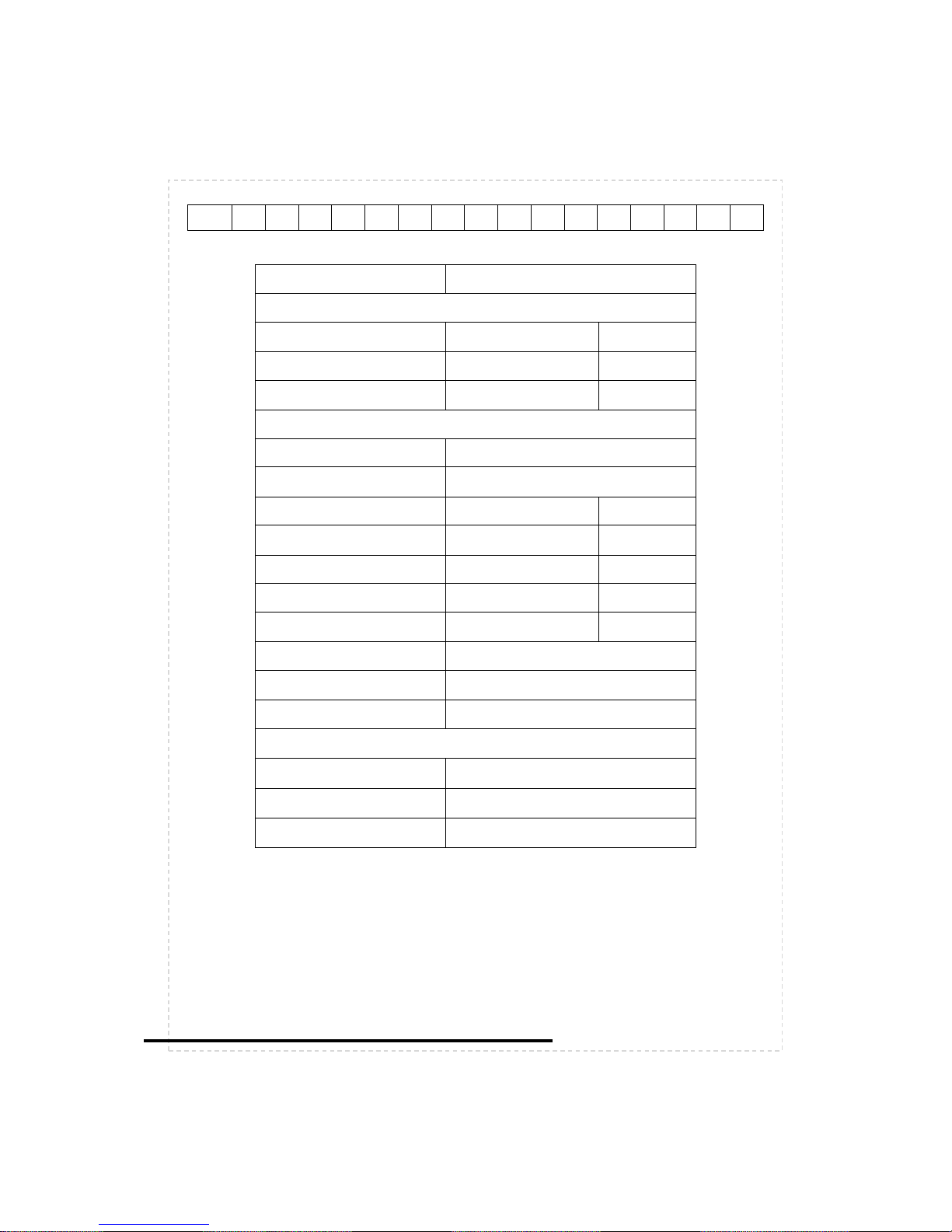
PLP
Pump serial number
Capacity
m3/h
Pressure bar
NPSH-r m
Drive supplier
Type
Speed min-1
Voltage /
/
V
Frequency
Hz
Current A
Power kW
Isolation class
Protection class
IP
ATEX Zone
Coupling supplier
Type
Dimensions
User manual Pomac PLP Lobe pump

User manual Pomac PLP Lobe pump
CE/PLP (1406) EN-12 3
This manual has been compiled with the utmost care.
However, POMAC assumes no liability for possible deficiencies of the information in this
manual. It is the responsibility of the buyer/user of this pump to ensure this information is
complete and up-to-date.
All technical information mentioned in this user manual remains property of Pomac bv and may
only be used for the installation, operation and maintenance of this pump. The information may
not be copied, duplicated or passed on to third parties without our written permission.
Copyright 2010 Pomac bv
Release date: June 2014
Doc. ID. : CE/PLP (1406) EN-12

User manual Pomac PLP Lobe pump
4 CE/PLP (1406) EN-12
DECLARATION OF INCORPORATION
(according to Annex II 1 B of the Machinery Directive (2006/42/EC – 1st Edition – December 2009)
Pomac bv
Feithspark 13
9356 BX Tolbert
The Netherlands
hereby declares completely under own responsibility that the pump mentioned below:
Model: Lobe pump
Type: PLP
Execution: bare shaft
Materials: 1.4404
to which this declaration refers to, is in conformity with the following standards:
Standards: EN-ISO 12100 parts 1 & 2
NEN-EN 60204 part 1
EN 809
The pump must not be put into service until the final machinery into which it is to be incorporated has
been declared in conformity with the provisions of this Directive (2006/42/EC), where appropriate.
Issued at Tolbert, 29th of December 2009
H. Poelstra
Managing Director

User manual Pomac PLP Lobe pump
CE/PLP (1406) EN-12 5
Table of contents
1. Introduction ....................................................................................................................................... 7
1.1. General information ................................................................................................................... 7
1.2. Warranty .................................................................................................................................... 7
1.3. Transport and receipt ................................................................................................................ 7
1.4. Manufacturer ............................................................................................................................. 7
2. Safety ............................................................................................................................................... 8
2.1. General information ................................................................................................................... 8
2.2. Instructions ................................................................................................................................ 8
2.3. Staff ........................................................................................................................................... 8
2.4. Changed application ................................................................................................................. 8
3. General information .......................................................................................................................... 9
3.1. Pump identification .................................................................................................................... 9
3.2. Operating principle .................................................................................................................. 12
3.3. Delivery program ..................................................................................................................... 12
3.4. Application area ...................................................................................................................... 12
3.5. Construction ............................................................................................................................ 13
3.6. Safety valve (optional)............................................................................................................. 14
3.6.1. Safety valve types ............................................................................................................ 14
3.6.2. Description of the safety valve ......................................................................................... 14
3.6.3. Connections of the air-loaded safety valve ...................................................................... 14
4. Installation ...................................................................................................................................... 15
4.1. General information ................................................................................................................. 15
4.2. Transport ................................................................................................................................. 15
4.3. Hoisting ................................................................................................................................... 15
4.4. Safety ...................................................................................................................................... 16
4.5. Foundation .............................................................................................................................. 16
4.6. Built-in dimensions .................................................................................................................. 16
4.7. Piping ...................................................................................................................................... 17
4.8. Pump with safety valve ........................................................................................................... 18
4.9. Pump-unit assembly ................................................................................................................ 18
4.10. Coupling alignment ................................................................................................................. 18
4.11. Alignment tolerances ............................................................................................................... 19
4.12. Fitting additional connections .................................................................................................. 19
4.13. Flushing the system ................................................................................................................ 21
4.14. Establishing the direction of rotation ....................................................................................... 23
4.15. Connecting the drive ............................................................................................................... 23
4.16. Oil filling ................................................................................................................................... 23
5. Operation ........................................................................................................................................ 24
5.1. Checking ................................................................................................................................. 24
5.2. Start Up ................................................................................................................................... 24
5.3. Adjusting the safety valve ....................................................................................................... 24
5.3.1. Adjusting a spring loaded safety valve ............................................................................ 24
5.3.2. Adjusting an air loaded safety valve ................................................................................ 25
5.4. In operation ............................................................................................................................. 26
5.5. Operating principle of the safety valve .................................................................................... 26
5.6. Shutting down ......................................................................................................................... 26
6. Maintenance ................................................................................................................................... 27
6.1. General survey ........................................................................................................................ 27
6.2. Oil change ............................................................................................................................... 27
7. Disassembly / assembly ................................................................................................................. 28
7.1. Ordering spare parts ............................................................................................................... 28
7.2. Safety measures ..................................................................................................................... 28
7.3. Special tools ............................................................................................................................ 28
7.4. Draining the pump ................................................................................................................... 29
7.5. Oil draining .............................................................................................................................. 29
7.6. Dismantling the pump ............................................................................................................. 29
7.7. Pump disassembly .................................................................................................................. 29
7.8. Disassembly of a safety valve ................................................................................................. 31

User manual Pomac PLP Lobe pump
6 CE/PLP (1406) EN-12
7.8.1. Disassembly of a spring loaded safety valve ................................................................... 31
7.8.2. Disassembly of an air loaded safety valve ...................................................................... 32
7.9. Parts inspection ....................................................................................................................... 32
7.10. Gearbox assembly .................................................................................................................. 33
7.11. Adjusting the axial rotor clearance .......................................................................................... 35
7.12. Shaft seal assembly ................................................................................................................ 37
7.12.1. Single mechanical seal assembly, types M1, M3 and M4 ........................................... 37
7.12.2. Double mechanical seal assembly, types M2, M5, M6 and M7 ................................... 37
7.12.3. O-ring seal assembly, types O1 and O2 ...................................................................... 37
7.12.4. Lip seal assembly, type L ............................................................................................. 38
7.13. Rotor assembly ....................................................................................................................... 38
7.14. Adjusting the timing of ‘quattro lobes’ ..................................................................................... 39
7.15. Front cover assembly .............................................................................................................. 39
7.16. Gearbox assembly .................................................................................................................. 40
7.17. Assembly of a safety valve ..................................................................................................... 41
7.17.1. Assembly of a spring-loaded safety valve .................................................................... 41
7.17.2. Assembly of an air-loaded safety valve ....................................................................... 41
7.18. Filling with oil ........................................................................................................................... 41
8. Closing down .................................................................................................................................. 42
8.1. Dismantling ............................................................................................................................. 42
8.2. Storage .................................................................................................................................... 42
8.3. Disposal .................................................................................................................................. 42
9. Technical data ................................................................................................................................ 43
9.1. Oil types .................................................................................................................................. 43
9.2. Oil quantities ........................................................................................................................... 43
9.3. Dimensions ............................................................................................................................. 44
9.4. Sectional drawing .................................................................................................................... 45
9.5. Parts lists ................................................................................................................................. 46
9.5.1. Part list with article numbers PLP 1 ................................................................................. 46
9.5.2. Part list with article numbers PLP 15 ............................................................................... 47
9.5.3. Part list with article numbers PLP 2 ................................................................................. 48
9.5.4. Part list with article numbers PLP 3 ................................................................................. 49
9.5.5. Part list with article numbers PLP 4 ................................................................................. 50
9.6. Materials specification ............................................................................................................. 51
9.7. Shaft seals .............................................................................................................................. 52
9.7.1. Single mechanical seal , type M1 .................................................................................... 52
9.7.2. Single mechanical seal , type M4 .................................................................................... 53
9.7.3. Double mechanical seal, type M2 .................................................................................... 54
9.7.4. Double mechanical seal, type M5 .................................................................................... 55
9.7.5. Double mechanical seal, type M6 .................................................................................... 56
9.7.6. Double mechanical seal, type M7 .................................................................................... 57
9.7.7. Single O-ring seal, type O1 .............................................................................................. 58
9.7.8. Double O-ring seal, type O2 ............................................................................................ 59
9.7.9. Lip seal, type L3 ............................................................................................................... 60
9.8. Spring loaded safety valve ...................................................................................................... 61
9.9. Air loaded safety valve ............................................................................................................ 62
10. Trouble shooting ......................................................................................................................... 63

User manual Pomac PLP Lobe pump
CE/PLP (1406) EN-12 7
1. Introduction
1.1. General information
This manual provides important information regarding the correct way of installing, operating
and servicing this pump.
This manual also provides information necessary to prevent the installer/operator from injury or
discomfort during installation and operation of this pump and to ensure the correct use and
reliable performance of this pump.
This manual represents the most recent information regarding the pump types mentioned in this
manual at the time of going to print. However, POMAC reserves the right to modify the
construction of the pump types mentioned, as well as the contents of this manual, without prior
or afterward notification.
Read this manual thoroughly before installing, operating or servicing this pump. Ensure
that operators and maintenance staff are familiar with the symbols used. Follow the
instructions in this manual step by step.
1.2. Warranty
Warranty is strictly limited to the conditions specified by POMAC and will only be granted
according to these conditions.
Warranty will only come into force provided that:
⚫ the pump has been installed and put into operation strictly in accordance with the
instructions given in this manual.
⚫ maintenance and repairs have been carried out according to the instructions given in this
manual.
⚫ exclusively original POMAC parts or parts provided by POMAC have been used for replacing
parts.
⚫ the pump has not been used for applications other than those shown in the specifications
according to which the pump was sold.
⚫ no changes have been made to the construction of the pump itself by the buyer.
⚫ the damage is not the result of work carried out by persons not qualified or appointed.
⚫ the damage has not been caused through major force.
1.3. Transport and receipt
⚫ Check to see if the pump has not been subject to damage during transportation. If this is the
case, report it directly to the carrier and to POMAC;
⚫ If the pump is delivered on a pallet, leave it on the pallet for as long as possible. This
facilitates internal transport.
1.4. Manufacturer
PLP lobe pumps are manufactured by
Pomac bv
Feithspark 13
9356 BX Tolbert
The Netherlands
Tel +31(0) 594 512877
Fax +31(0) 594 517002
info@ pomacpumps.com
www.pomacpumps.com

User manual Pomac PLP Lobe pump
8 CE/PLP (1406) EN-12
2. Safety
2.1. General information
This manual provides information necessary to prevent the installer/operator from injury or
discomfort during installation and operation of this pump and to ensure the correct use and
reliable performance of this pump.
⚫ Read this manual thoroughly before installing, operating or servicing this pump.
⚫ Ensure that operators and maintenance staff are familiar with the contents of this manual
and with the instructions given.
⚫ Ensure that operators and maintenance staff are familiar with the symbols used.
⚫ Follow the instructions in this manual step by step.
⚫ Store this manual in a place that is known and accessible to any user.
2.2. Instructions
This manual contains instructions with regard to the safety of the user, the continued good
functioning of the pump and hints to facilitate certain actions or procedures.
These instructions are indicated with the following symbols:
Warning! Can cause injury to the user! Act strictly in accordance with the instructions
given!
! Caution! Can cause severe damage to the pump or bad functioning! Closely follow the
instructions given!
Note: Hint or instruction that can facilitate certain actions.
⚫ Issues which require extra attention are printed in bold.
2.3. Staff
All personnel, in charge of the installation, operation or maintenance and overhaul of the pump,
should have received the necessary training.
2.4. Changed application
⚫ Contact POMAC in case the pump is going to be used for other applications or in different
circumstances than those specified during the initial pump selection.
User manual Pomac PLP Lobe pump
CE/PLP (1406) EN-12 9
3. General information
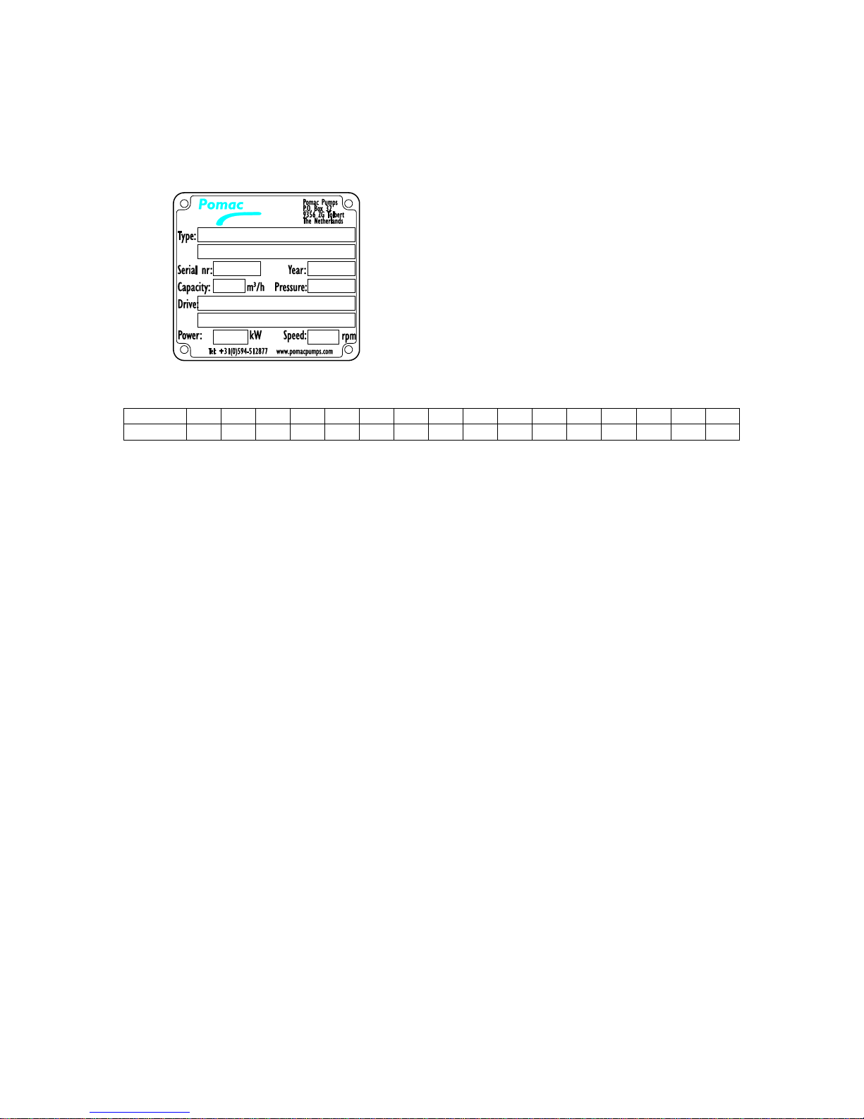
3.1. Pump identification
Each pump has a unique serial number and a type number. Both are stated on the type plate of
the pump.
The type number describes the set-up of the pump and is composed as follows:
PLP *)
x x x.. x x x x x x.. x x x x x x x 1 2 3 4 5 6 7 8 9 10
11
12
13
14
15
16
*) PLPH in case of hydraulic drive,
PLPS in case of split pump casing.
Example: PLP 2-2 / M / 01 / 01 / M1 / V / V / P2 / S1 / C1 / O1 / G1 / H1 / V1 / R1 / W1
1. Pump type
1-3/4 = ¾” or DN15
1-1 = 1” or DN25
1-1,5 = 1,5” or DN40
15-2 = 2” or DN50
2-1,5 = 1,5” or DN40
2-2 = 2” or DN50
2-2,5 = 2,5” or DN65
3-2 = 2” or DN50
3-3 = 3” or DN80
3-4 = 4” or DN100
4-4 = 4” or DN100
2. Connection dimensions
I = Imperial system (Inch)
M = Metric system (DN)
3. Connection type suction side
01 = hygienic thread acc. to DIN 11851
02 = SMS 1145
03 = Tri-Clamp DIN32676
04 = Aseptic thread DIN 11864-1
05 = Aseptic flange DIN 11864-2
06 = flanges acc. to EN1092-1
07 = BSP-thread
08 = NPT-thread
09R = rectangular flange right side as seen from shaft end
09L = rectangular flange left side as seen from shaft end
09T = rectangular flange on top
10 = Aseptic Tri-Clamp DIN 11864-3
xx = acc. to client specification

User manual Pomac PLP Lobe pump
10 CE/PLP (1406) EN-12
The codes at pos. .. determine the position of the suction connection.
For horizontal pump position:
For vertical pump position:
R = suction position at right hand side, seen from shaft end.
T = suction position = top
L = suction position at left hand side, seen from shaft end.
B = suction position = bottom
4. Connection type discharge side
01 = hygienic thread acc. to DIN 11851
02 = SMS 1145
03 = Tri-Clamp DIN32676
04 = Aseptic thread DIN 11864-1
05 = Aseptic flange DIN 11864-2
06 = flanges acc. to EN1092-1
07 = BSP-thread
08 = NPT-thread
09R = rectangular flange right side as seen from shaft end
09L = rectangular flange left side as seen from shaft end
10 = Aseptic Tri-Clamp DIN 11864-3
xx = acc. to client specification
5. Type shaft seal
M1 = single mechanical seal SiC/SiC
M2 = double mechanical seal quench or flush SiC/SiC - SiC/SiC
M3 = single mechanical seal with small seal faces SiC/SiC
M4 = single mechanical seal TC/TC
M4V = retracted single mechanical seal TC/TC
M5 = double mechanical seal quench or flush TC/TC - TC/TC
M6 = double mechanical seal quench or flush TC/TC - SiC/SiC
M7 = double mechanical seal quench or flush SiC/SiC - TC/TC
O1 = single O-ring, stainless steel shaft sleeve
O2 = double O-ring with quench, stainless steel shaft sleeve
L3 = WDR PTFE lip seal, ceramic coated stainless steel shaft sleeve
6. Elastomers shaft seal
E = EPDM acc. FDA & EC1935/2004
V = Viton acc. FDA & EC1935/2004
T = Teflex FEP/VITON acc. FDA & EC1935/2004
K = FFKM acc. FDA & EC1935/2004
N = NBR
S = Silicone
X = acc. to client specification
7. Elastomers static O-rings
E = EPDM acc. FDA & EC1935/2004
V = Viton acc. FDA & EC1935/2004
T = Teflex FEP/VITON acc. FDA & EC1935/2004
K = FFKM acc. FDA & EC1935/2004
N = NBR
S = Silicone
X = acc. to client specification

User manual Pomac PLP Lobe pump
CE/PLP (1406) EN-12 11
8. Position connections and shaft
P0 = connections horizontal, shaft top = standard,
P1 = connections horizontal, shaft bottom
P2 = connections vertical, shaft right hand from shaft end
P3 = connections vertical, shaft left hand from shaft end
9. Self-draining execution
S1 = 45°
S2 = plane
S3 = 2x 45°
10. Additional radial / axial clearance between lobe and pump casing,
C = Radial clearance at the lobe circumference and axial clearance at the rear and front side
C1 = + 0,05
C2 = + 0,1
C3 = + 0,15
C4 = +0,2
C–1 = – 0,05
11. Internal surface treatment
O1 = mechanical polish to 0,8 micron
O2 = electro polish to 0,5 micron
12. Hardened pump parts
G1 = pump casing, lobes, cover, Hardened acc. FDA
G2 = pump casing, cover, Hardened acc. FDA
G3 = lobes, Hardened acc. FDA
G4 = pump casing, lobes, cover, Plasma nitrided (non-FDA)
G5 = pump casing, cover, Plasma nitrided (non-FDA)
G6 = lobes, Plasma nitrided (non-FDA)
13. Heating jacket
H1 = heating jacket on front cover
H2 = heating jacket on rotor case
H3 = H1 + H2
H4 = Electrical pump cover heating
14. Safety relief valve
V1 = safety relief valve, spring-loaded
V2 = safety relief valve, pneumatically controlled
15. Lobes / timing mechanism
R1 = Bi-Wing lobe with timing mechanism
R2 = Quattro lobe with timing mechanism
16. Material options.
W1 = pump casing, lobes, pump cover: 1.4435
W2 = lobes non-galling
W3 = pump casing, lobes, pump cover: Hastelloy CX2MW N26022
W4 = pump casing, lobes, pump cover: 1.4571, 316 Ti

User manual Pomac PLP Lobe pump
12 CE/PLP (1406) EN-12
3.2. Operating principle
A lobe pump is a rotary positive displacement pump. The operating principle is based on the
counter-rotation of 2 rotors in a chamber. Both rotors are mounted on shafts. The shafts are
supported by bearing cartridges, which are directly mounted to the pump casing. One of the
shafts is externally driven. An internal gear transmission drives the other shaft in opposite
direction. The rotors run synchronously in the opposite directions, without touching each other.
When the rotors pass the suction port the volume between the rotors increases. This creates a
pressure decrease which causes the liquid to flow into the suction port. During rotation a fixed
amount of liquid is conveyed.
When the rotors approach the pressure port the volume between the rotors decreases. This
creates a pressure increase which causes the liquid to flow out of the pressure port.
3.3. Delivery program
Connections
The delivery program comprises pump types with connections of ¾”, 1”, 1 ½”, 2", 2 ½”, 3" and
4".
The pump can be placed with its connections either horizontally or vertically.
Shaft seals
The following shaft seal variants are available:
⚫ Single mechanical seal
⚫ Double mechanical seal, quenched or flushed
⚫ O-ring seal
⚫ Double O-ring seal, quenched
⚫ Lip seal.
3.4. Application area
Type
displacement
[lit/100 rev.]
max. pressure
[bar]
max. speed
[rev./min]
weight [kg]
PLP 1- ¾
4
15
1500
12
PLP 1-1
6
15
1500
12,5
PLP 1-1,5
10
15*
1200
13
PLP 15-2
20
8
1200
23,2
PLP 2-1,5
22
15
1200
37
PLP 2-2
30
15
1200
39
PLP 2-2,5
36
15*
1000
44
PLP 3-2
55
15
1000
101
PLP 3-3
100
15
1000
105
PLP 3-4
130
15*
750
115
PLP 4-4
250
15
750
295
*) Dependent on the gap between rotor and pump casing.
The values mentioned above are maximum values. The operational values may be lower
because of the liquid characteristics or the system design.

User manual Pomac PLP Lobe pump
CE/PLP (1406) EN-12 13
3.5. Construction
The pump comprises of the following parts:
User manual Pomac PLP Lobe pump
14 CE/PLP (1406) EN-12
3.6. Safety valve (optional)
3.6.1. Safety valve types
The PLP can be supplied with a spring-loaded or air-operated safety valve. The opening
pressure is adjustable by means of a setscrew.
The following types can be provided with a safety valve:
PLP 1-3/4
PLP 1-1
PLP 1-1.5
PLP 15-2
PLP 2-1.5
PLP 2-2
PLP 2-2,5
PLP 3-2
PLP 3-3
PLP 3-4
PLP 4-4
spring loaded
safety valve
V V V
V
air-operated
safety valve
V
3.6.2. Description of the safety valve
The Pomac safety valve is mounted directly to the pump cover. This facilitates maintenance and
guarantees optimal hygienic conditions. When the valve opens a direct by-pass is created
between pressure side and suction side of the pump.
The valve covers almost completely the front side of the rotors and the spaces on suction side
and pressure side partially. At pump side the valve is submitted to the differential pressure
inside the pump; the air pressure or spring load exerts the external force on the valve. Because
fluid characteristics, pressure division, process factors, etc. all can influence the load
characteristic on the valve, the load must be adjusted on-site.
When the differential pressure inside the pump exceeds the closing pressure, exerted by the
load set, the valve will open. Dimensions of valve and valve housing are such, that a part of the
pump capacity can be by-passed from pressure side to suction side.
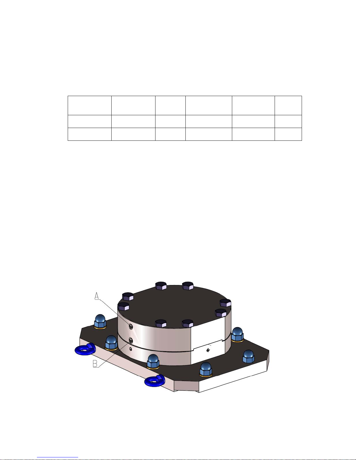
3.6.3. Connections of the air-loaded safety valve
Connection A : Air pressure
Connection B : Valve vent (always has to be open)
.
User manual Pomac PLP Lobe pump
CE/PLP (1406) EN-12 15
4. Installation
4.1. General information
⚫ The foundation must be solid, flat and level.
⚫ The area, in which the pump is placed, must be well vented. Too high a temperature or air
humidity, or a dusty atmosphere, may have negative effects on the performance of an
electric motor.
⚫ The area around the pump-unit must be sufficient for the pump to be operated, cleaned or
repaired.
⚫ To ensure an unobstructed air supply to an electric motor there must be a free space behind
the fan cover, equal to 1/4 of its diameter.
All work on and with the pump must always be in accordance with all the prevailing
standards regarding occupational health and safety as well as machine safety.
4.2. Transport
⚫ In case the pump or the pump-unit is delivered on a pallet, leave it on the pallet as long as
possible. This will facilitate the internal transport.
4.3. Hoisting
⚫ If there is a proper hoisting device available, use this to move the pump(-unit).
Never stand underneath a hoisted pump!
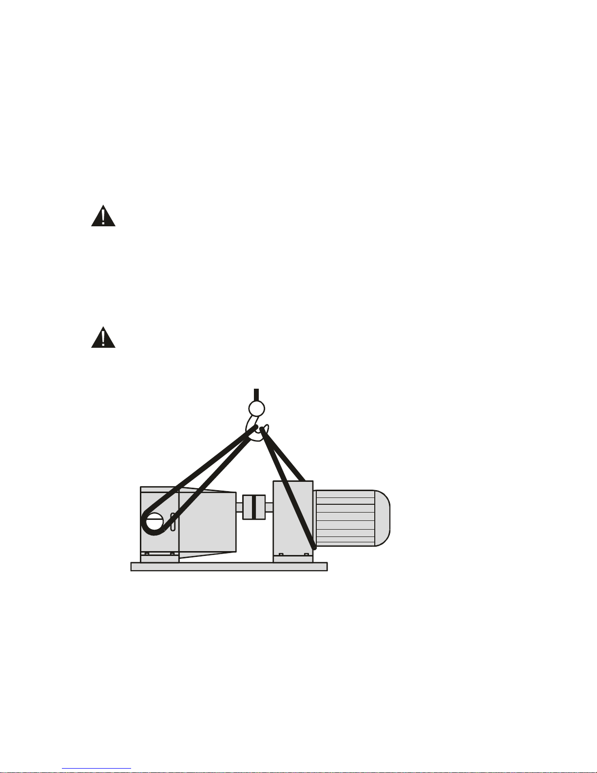
⚫ In case the pump is assembled with a motor on a baseplate, the pump-unit must always be
hoisted with the straps fixed as shown in the following figure:
User manual Pomac PLP Lobe pump
16 CE/PLP (1406) EN-12
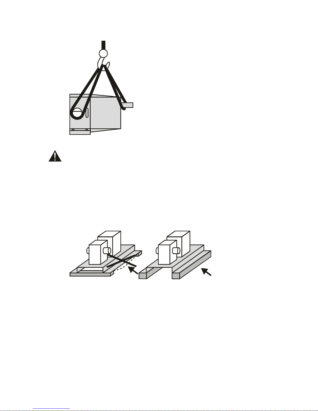
⚫ In case a single pump must be hoisted, fix the straps as follows:
4.4. Safety
Never insert fingers into the rotor case or into the connection ports. Even manually
rotating the shaft can cause injury!
! If the risk exists of exceeding the maximum working pressure a safety device must be
fitted to the pump, the drive or the system!
4.5. Foundation
⚫ The foundation must be solid, flat and level.
⚫ Take into consideration the need for draining facilities.
⚫ The entire weight of the baseplate should rest level on the foundation. The baseplate may
not bend!
4.6. Built-in dimensions
⚫ The proper built-in dimensions of the pump are incorporated in the dimensions sketch,
supplied separately with the pump (-unit).
⚫ See paragraph 9.2 for the main dimensions of the single pump.
User manual Pomac PLP Lobe pump
CE/PLP (1406) EN-12 17
4.7. Piping
The piping must meet the following requirements:
General
⚫ Ensure the piping is sufficiently supported, especially besides the inlet and outlet ports. The
piping should be fully supported independently from the pump.
⚫ The connections must be fitted square to the pump.
⚫ The lines must be fitted and connected stress-free.
! Piping which is fitted obliquely, insufficiently supported or exerting force to the pump,
may cause serious damage to the pump!
⚫ Check if the piping shows any visible leakage.
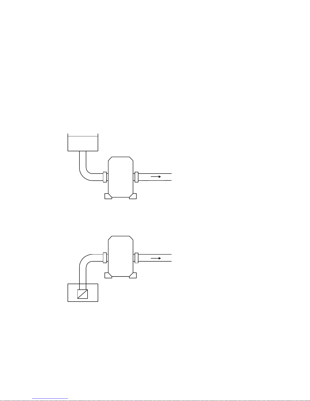
Inlet piping
⚫ It is recommended to place the pump below the supply liquid level. A flooded suction
reduces the presence of air in the system.
Non-return valves
⚫ In case the pump is installed above the supply liquid level fit a non-return valve to the foot of
the suction line to keep it filled with liquid. This applies especially when low-viscous liquids
are conveyed.
User manual Pomac PLP Lobe pump
18 CE/PLP (1406) EN-12
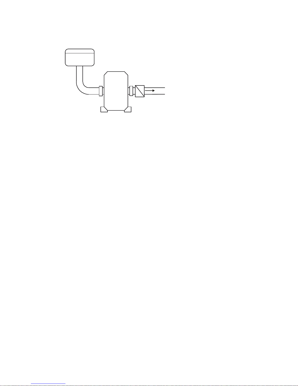
⚫ For systems that convey liquid under vacuum, a non-return valve in the delivery line is
recommended. This prevents backflow of air or liquid.
4.8. Pump with safety valve
If the pump is provided with a safety valve to the pump cover, it is compulsory to install a
pressure gauge at pressure side and a shut-off valve directly after the pressure gauge!
⚫ The pressure gauge must have a measuring range of at least 0-25 bar.
4.9. Pump-unit assembly
In case the pump is supplied as a single pump, it needs to be assembled to a drive and a
baseplate.
Do the following:
1. Place the pump onto the baseplate and fit it with retaining bolts.
2. Fit a coupling half to the pump shaft.
3. Fit the other half to the drive shaft of the drive.
4. Fit the drive to the baseplate. Leave a 3 mm gap between both coupling halves.
5. Place copper shims under the feet of the drive to bring it on a level with the pump. Fix the
drive.
6. Align the coupling according to the following instructions.
4.10. Coupling alignment
After the assembly and set-up of the pump-unit the alignment of the coupling needs to be
checked.
! Always check the alignment after hoisting the pump-unit up to its baseplate!
Misalignment can lead to excessive wear, increased motor temperature and noise level.
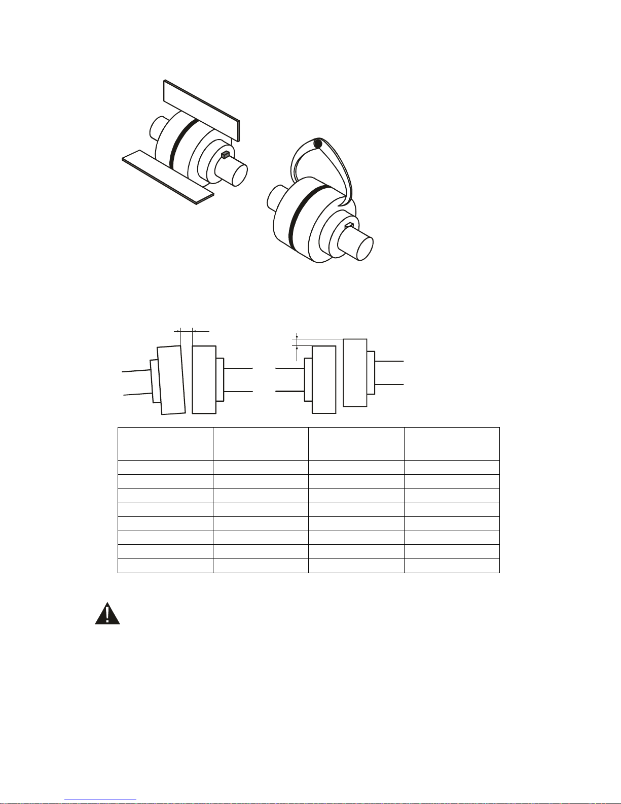
Check the alignment, using special alignment equipment, or do the following:
1. Place a ruler on the coupling. It must be adjacent to the entire width of the coupling halves,
see figure.
2. Repeat this check at 3 different positions around the coupling.
3. Check the alignment with a pair of outside callipers at 2 diametrically opposite positions of
the coupling sides, see figure.
4. If the measured values are outside the tolerance limits, slightly loosen the retaining bolts of
the drive and move the drive until the values are within their tolerance limits. Fix the retaining
bolts again.
5. When the coupling is well aligned mount the coupling guard.
User manual Pomac PLP Lobe pump
CE/PLP (1406) EN-12 19
4.11. Alignment tolerances
The following table with its corresponding figure shows the tolerance limits for aligning the
coupling.
A
E
Coupling outer
diameter [mm]
A must be between
[mm]
Max difference
between A max and
A min [mm]
E must be between
[mm]
81-95
2 - 4
0,15
0 - 0,15
96-110
2 - 4
0,18
0 - 0,18
111-130
2 - 4
0,21
0 - 0,21
131-140
2 - 4
0,24
0 - 0,24
141-160
2 - 6
0,27
0 - 0,27
161-180
2 - 6
0,30
0 - 0,30
181-200
2 - 6
0,34
0 - 0,34
201-225
2 - 6
0,38
0 - 0,38
4.12. Fitting additional connections
Ensure the engine cannot be started when work is performed to the pump-unit and the
rotating parts are not completely covered!
! Ensure that the whole system is thoroughly flushed and cleaned. The whole system must
be free from debris and particles, because they could get into the pump and cause
serious damage to rotors and rotor case!
! A pump which is NOT equipped with a QUENCHED shaft seal (see type description), may
NEVER be installed in a position where it possibly could run DRY!

User manual Pomac PLP Lobe pump
20 CE/PLP (1406) EN-12
Flushing
⚫ When equipped with shaft seal type M1, M2 or O2: Connect the flush pipes to the shaft
seal chamber, through the openings in the rotor case. The connections are threaded R1/8.
⚫ In case a low-pressure quench (shaft seal types M2, M5, O2 and O4) is applied, the
flushing system must have a capacity of 0,25 l/min at 0,5 mwc. In case the pump is
vertically mounted the QUENCH SUPPLY LINE SHOULD BE CONNECTED TO THE
LOWER SIDE!
⚫ In case a pressurised flush (shaft seal types M2 and M5) is applied, the pressure of the
flushing system must be 2 bar higher than system pressure. In case the pump is vertically
mounted the FLUSH SUPPLY LINE SHOULD BE CONNECTED TO THE LOWER SIDE!
Heating
⚫ When fitted with heating jackets: connect this device to the heat supply.
 Loading...